STEPPING MOTOR CONTROLS - Motor Technology Ltd
STEPPING MOTOR CONTROLS - Motor Technology Ltd
STEPPING MOTOR CONTROLS - Motor Technology Ltd

You also want an ePaper? Increase the reach of your titles
YUMPU automatically turns print PDFs into web optimized ePapers that Google loves.
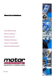
<strong>STEPPING</strong> <strong>MOTOR</strong> <strong>CONTROLS</strong><br />
Power amplifier boards<br />
Position controls<br />
Equipment
DRIVING<br />
MOTION CONTROLING<br />
POSITIONING<br />
All rights reserved<br />
Without written approval we don’t allow any reprint and partial copying.<br />
We reserve the right to make engineering changes, refinements and improvements<br />
to all products described herein.<br />
Mechanical and electrical ratings and dimensions are, therefore, subject to<br />
change without notice.<br />
No liability whatsoever is accepted.<br />
Edition: April 2002
3 index<br />
Seite<br />
General product overview<br />
Stepping motor controls<br />
general explanations<br />
Stepping <strong>Motor</strong> power amplifier boards<br />
series SE...V1 and SE...E50 V1<br />
series SE P05 microstepping<br />
Power supplies<br />
Front panels and board holder<br />
Panel mountage-/ 19 inch-system series ELK / ELR<br />
Position controls<br />
series SERS<br />
Series SERC and SERS equipment<br />
4<br />
5<br />
6<br />
9<br />
10<br />
11<br />
12<br />
16<br />
23
4 General procuct overview<br />
STÖGRA Stepping motor controls are designed as modular system as well as STÖGRA Stepping motors (see catalogue<br />
<strong>STEPPING</strong> <strong>MOTOR</strong>S)<br />
RS232<br />
RS485<br />
Profibus-DP<br />
CANopen<br />
SERCOS<br />
PC<br />
PLC<br />
CNC<br />
board holder<br />
KHD32<br />
panel mountage/<br />
19 inch rack system<br />
optionally with powersupply<br />
1 until 8 plug ports for drives<br />
ELK/ELR<br />
powersupply<br />
NT<br />
PC<br />
PLC<br />
CNC<br />
including<br />
position control<br />
pulse<br />
direction<br />
position control with<br />
power amplifier<br />
series SERS...<br />
SM56 SM87 SM107 SM168<br />
stepper motors<br />
series SM...<br />
power amplifier boards<br />
series SE...<br />
Overview Controls<br />
Power amplifier boards<br />
Series SE... V11/13<br />
Voltage supply Phase current Step resolution<br />
24 - 240 VDC 1 - 14,5 A/Ph. 200 - 1000 steps/rev.<br />
catalogue page 6 to 8<br />
position control<br />
with RS232,<br />
RS485<br />
position control<br />
with SERCOS<br />
Power amplifier boards with control of step angle<br />
SE ... E50 V11/V13<br />
Voltage supply Phase current Step resolution<br />
24 - 240 VDC 1 - 14,5 A/Ph. 200 - 1000 steps/rev.<br />
catalogue page 6 to 8<br />
Mikroschritt-Leistungsverstärkerkarten<br />
Serie SE P05<br />
Voltage supply Phase current Step resolution<br />
24 - 240 VDC 1 - 14,5 A/Ph. 200 - 12800 steps/rev.<br />
catalogue page 9<br />
Positioniersteuerungen<br />
Serie SERS mit Schnittstellen<br />
RS232, RS485, Profibus-DP, CANopen, SERCOS<br />
Voltage supply Phase current Step resolution<br />
24 - 240 VDC 1 - 14,5 A/Ph. 12800 steps/rev.<br />
catalogue page 16 to 23<br />
interface<br />
Profibus-DP<br />
CANopen<br />
control board<br />
with interface<br />
to position control<br />
encoder/<br />
handwheel board<br />
power amplifier board<br />
heat sink with power semiconductors<br />
heat sink KR6<br />
KR12<br />
control board with<br />
pulse / direction<br />
interface<br />
STÖGRA Stepping motor controls are designed as modular system The power stage with the power semi conductors is used<br />
for the power amplifier boards as well as for the Position controls. The different field bus interfaces for the position controls are realized<br />
by internal plug boards. This enables a great type variety for the most different requirements and many different control systems<br />
and never the less the possibility to keep most parts (basic components) on stock and cost effective production due to the low quantity<br />
of different basic types.
5 STÖGRA Stepping motor controls<br />
General function principle - Step resolution and max. load angle (accuracy of positioning)<br />
Ι<br />
vector after<br />
1. full step<br />
phase 2<br />
ϑ<br />
full step<br />
electrical 90°<br />
mechanical 1.8°<br />
zero position<br />
part phase 2<br />
phase 1<br />
quarter step<br />
electrical 22.5°<br />
mechanical 0.45°<br />
micro step<br />
electrical e.g. 4.5°<br />
mechanical e.g. 0.09°<br />
phase 2<br />
half step<br />
electrical 45°<br />
mechanical 0.9°<br />
zero position<br />
phase 1<br />
phase current at half step<br />
(400 steps/rev.)<br />
Ι<br />
t<br />
t<br />
part phase 1<br />
vector after<br />
2. full step<br />
vector after<br />
3. full step<br />
phase current at micro step<br />
(12800 steps/rev.)<br />
Switching onwards the stator field - shown in a field-vector-diagram :<br />
Md<br />
ϑ = 1,8°<br />
ϑ = 0.9°<br />
ϑ = 0.45°<br />
Mmax<br />
Md<br />
M[Nm]<br />
zeroposition<br />
1.8 3.6 5.4<br />
ϑ[°]<br />
-3.6 -1.8 0 1.8 3.6 5.4 7.2<br />
ϑ<br />
ϑ[°]<br />
zero position after<br />
1. full step<br />
zero position after<br />
2. full step<br />
zero position after<br />
half / full steps<br />
Mmax<br />
Switching onwards the stator field shown in a<br />
load angle - operating torque - diagram :<br />
Load angle: Excursion . . of the rotor in reference to the zero position determined<br />
by the stator field, in case of a torque Md at the motor shaft<br />
A stepping motor having 50 teeth on the rotor surface (motor with 50<br />
poles) produces every 7,2° (mechanically) a stabile position (zero position)<br />
at motor stand still - regardless the number of phases (2, 3 or 5<br />
phases)! The zero position is determined by the stator field.<br />
The stator field is moved from the power amplifier »step by step« and<br />
the rotor follows the stator field. In case of big steps (full step - 200<br />
steps/rev. , half step - 400 steps/rev.) and low speed the motor is running<br />
rough with strong vibrations. Smaller steps result in smoother running.<br />
At high step resolutions (e.g. 12800 steps/rev.) there will be a very<br />
smooth true running without vibrations.<br />
At motor stand still, in case of a load (torque Md), the<br />
motor shaft will be moved the angle ϑ out of its zero<br />
position. The maximum possible movement away<br />
from the zero position is -1.8° at -Mmax and +1.8° at<br />
Mmax independent of the step resolution and 2, 3<br />
or 5 phases (!!!) (in case of a rotor with 50 teeth)<br />
Practically in most applications there can be achieved<br />
between 0.1 ° and 0.9° accuracy of positioning<br />
(in case of sufficient step resolution of the control),<br />
depending on the mechanics (friction, etc.) and the<br />
calcukation of the motor.<br />
ϑ<br />
Md<br />
General specifications of STÖGRA Stepping motor amplifier boards:<br />
Q All boards can be configurated easily via solder bridges (e.g. selection of step angle, signals Low/High-active or activating of<br />
phase current reduction)<br />
Q The integrated control of step angle in series SE ... E50 V.. together with a stepping motor with mounted encoder E50 enables<br />
the evaluation of a mechanical overload (synchronous running interrupted) at the stepping motor. Therfore the load angle of the<br />
stepping motor is controlled.<br />
Q LEDs enable quick and easy diagnostics of error and status. During operation the status of the phases is displayed by four<br />
red LEDs. An electrical error - short circuit (motor phases), over temperature (amplifer) or undervoltage - is displayed by a yellow<br />
LED. At series SE ...E50 V1 a mechanical error (exceeding of the max. load angle e.g. in case of mechanical overload at<br />
the stepping motor) is displayed by another yellow LED.<br />
Q Error signals respective a ready signal can be used externally via a potential free output.<br />
Q STÖGRA power amplifier boards are plug compatible to each other, also to former series SE 11 ...60 and SE ...120.<br />
Series SE ...E50 V1.. is compatible to the former series SE...E50 and SE...E50D. Series SE...V1.. is compatible tothe former<br />
series standard series SE... (e.g. SE 400.06.60) and to series SE...B2.
6 Stepping motor control amplifier board series SE...V1 and SE...E50 V1<br />
General notes<br />
Q Control of 2-phase-stepping motors<br />
Q Compatible with STÖGRA and Zebotronics standard amplifier boards series SE ...., SE ... E50, SE ... E50 D..<br />
Q Supply voltage - nominal voltage : 24 VDC to 240 VDC<br />
Q Phase current range 0 A/phase - 14,5 A/phase<br />
Q Boards SE ... E50 V1.. with integrated load angle control<br />
- together with Zebotronics E50 encoder (50 impulses per channel and revolution) at the motor<br />
( also available SE ... E200 V1.. for HP H200 encoder - 200 impulse per channel and revolution)<br />
Q Protection against shortcircuit, overtemperature and undervoltage<br />
Q Via solder bridges adjustable step angles: 200, 400 , 500 , 800 and 1000 steps per revolution<br />
Q EMC according to EN55011 class B and EN50082-2<br />
Versions - connector system and signal level of the inputs<br />
Q SE ... E50 V11 : Encoder connections via 9 pole D-Sub, all other signals and connections via 32 pole male connector<br />
(DIN 41612 type D) and SPS(PLC)-input signal level<br />
Q SE ... E50 V13 : Encoder connections via 9 pole D-Sub , all other signals and connections via 32 pole male connector<br />
(DIN 41612 type D) and TTL-input signal level<br />
Q SE ... V11 : All signals and connections via 32 pole male connector (DIN 41612 type D) and SPS(PLC)-input signal level<br />
Q SE ... V13 : All signals and connections via 32 pole male connector (DIN 41612 type D) and TTL-input signal level<br />
Dimensions<br />
yellow LED:<br />
electrical error<br />
yellow LED:<br />
mechanical error<br />
(for"E50")<br />
46<br />
34<br />
19 19<br />
4A per phase<br />
6A per phase<br />
8A/12A per phase<br />
160<br />
172<br />
182<br />
32 - pole male connector<br />
DIN 41612 type D<br />
potentiometer<br />
type label<br />
90<br />
100<br />
4 res LEDs:<br />
state of excitation<br />
phases I and II<br />
9-pole D-Sub<br />
only for "E50"<br />
heat sink<br />
depending on<br />
phase current<br />
(1A and 2A<br />
without<br />
heat sink<br />
SE 400.04.85 V13<br />
SE 400.01.85 V13<br />
SE 400.02.24 V13<br />
Dimensions series SE... V11/13<br />
SE 400.04.85.E50 V13<br />
SE 400.08.120 V13<br />
SE 400.12.120 V13<br />
Selectable adjustments<br />
All adjustments can be made via<br />
(marked) solder bridges on the rearside<br />
of the logic board.<br />
L<br />
H R W0 W1 M F<br />
selectable adjustments series SE ...V1.. / SE ... E50 V1..<br />
marker<br />
R<br />
W0,W1<br />
L-H<br />
denotes<br />
open: automatic current reduction 50% standstill<br />
closed: no current reduction<br />
step angle adjustment (see table below)<br />
L open, H closed: input signals HIGH - active<br />
(The rising edge of the pulse signal is significant)<br />
L closed, H open: input signals LOW-active<br />
(The falling edge of the pulse signal is significant)<br />
! Attention: Don’t close L and H ! ( short circuit! )<br />
Step angle adjustments<br />
X = marker closed<br />
0 = marker open<br />
SE 400... V1. SE 200... V1.<br />
W1 W0 steps/rev. steps/rev.<br />
0 0 800 200<br />
0 X 400 400<br />
X 0 1000 -<br />
X X 500 -<br />
Automatic current reduction<br />
( marker »R« open )<br />
The phase current - adjustable via potentiometer- is set for nominal<br />
operation. If marker »R« is open, the phase current will be<br />
reduced by 50% at standstill of the motor. The first pulse increases<br />
the phase current again to the adjusted nominal value. At<br />
active Reset input, the current reduction will be disabled.
7 Stepping motor control amplifier board series SE...V1 and SE...E50 V1<br />
Supply voltage (working range)<br />
(Nominal) supply voltage [VDC]<br />
Working range [VDC]<br />
U B [VDC] (motor enabled)<br />
U M [VDC]<br />
(motor current ON)<br />
24<br />
20 - 36<br />
18<br />
16<br />
60 u. 85<br />
120<br />
50 - 85<br />
60 - 120<br />
43<br />
50<br />
32<br />
38<br />
U B and U M<br />
+ 5%<br />
240<br />
130 - 240<br />
120<br />
100<br />
Current adjustment<br />
Ex factory the amplifier board is set to nominal current. Via the potentiometer at the board frontside the phase current can be<br />
adjusted (the board must be in Reset state -> input signal Reset is set or power-ON Reset -> only LED "0" is lightning (see figure<br />
below). The voltage between measuring point B and point GND is proportional to the phase current (see table below)<br />
SE ... E50 V11 and SE ... E50 V13<br />
SE ... V11 and SE ... V13<br />
Nominal phase current<br />
Typ<br />
1 A/Ph.<br />
SE ...01...<br />
2 A/Ph.<br />
SE ...02...<br />
4 A/Ph.<br />
SE ...04...<br />
6 A/Ph.<br />
SE ...06...<br />
12 A/Ph.<br />
SE ...12...<br />
8 A/Ph.<br />
SE ...08...<br />
measured voltage<br />
adjusted phase current<br />
%<br />
300 mV<br />
100%<br />
150 mV<br />
50%<br />
max. adjustable current<br />
[A/Ph]<br />
1<br />
0,75<br />
1.4<br />
[A/Ph]<br />
2<br />
1<br />
2.8<br />
[A/Ph]<br />
4<br />
2<br />
5.6<br />
[A/Ph]<br />
6<br />
3<br />
8.4<br />
[A/Ph]<br />
12<br />
6<br />
14.5<br />
measured voltage<br />
267 mV<br />
133 mV<br />
[A/Ph]<br />
8<br />
4<br />
11.2<br />
Output signals<br />
SE ... [E50] V11 and SE ... [E50] V13 :<br />
Ready signal: Indication of an electrical error or a mechanical<br />
error (at SE...E50 V..).<br />
In non error state the relay contact is closed.<br />
electrical error/<br />
mechanical error<br />
a12<br />
c12<br />
ready signal<br />
-electrical error / mechanical error<br />
potential free contact<br />
I = 100 mA<br />
U = 50 VDC<br />
Input signals<br />
Output circuit SE...V11 / SE...V13 and SE...E50 V11 / SE...E50 V13<br />
Boost: Increases the phase current by 20%.<br />
Disable: Switches off the phase current.<br />
Reset: Sets the unit in zero position - phase zero. A pulse signal is ignored and errors are reset.<br />
Direction: Controls the motor direction.<br />
Pulse: With every pulse the motor will execute one step.<br />
Step angle: Divides the step resolution by two from 1000 or 800 to 500 or 400 steps per revolution.<br />
The input is always LOW-active - works only with open marker W0.<br />
Input signals e.g.: HIGH-active Input signals SPS - V11 Input signals TTL - V13<br />
signal input<br />
4K7<br />
L<br />
H<br />
direction<br />
0V<br />
13,5 - 30V<br />
max. 7V<br />
> 5µs > 5µs<br />
direction<br />
0V<br />
3,5 - 24V<br />
max. 1V<br />
> 5µs > 5µs<br />
Specification of<br />
other input signals<br />
is as<br />
»direction«<br />
4K7<br />
680 pF<br />
1 1<br />
pulse<br />
0V<br />
13,5 - 30V<br />
max. 7V<br />
pulse<br />
0V<br />
3,5 - 24V<br />
max. 1V<br />
signal rise time max.: 1µs , signal fall time max.: 1µs , frequency pulse max.: 45 KHz
8 Stepping motor control amplifier board series SE...V1 and SE...E50 V1<br />
Technical specifications<br />
Protection of the device<br />
Protection IP 00<br />
Protection against shortcircuit, overtemperature and undervoltage<br />
Weight<br />
Nominal current 1 A/Ph 2 A/Ph 4 A/Ph 6 A/Ph 8 A/Ph 12 A/Ph<br />
Weight 0,2 Kg 0,2 Kg 0,52 Kg 0,77 Kg 1,1 Kg 1,1 Kg<br />
Ambient conditions<br />
Ambient temperature : 0°C to 50°C<br />
max. heat sink temperature : 85°C<br />
Forced draft : for amplifier boards with nominal current 8A and 12A<br />
Noise immunity<br />
In case of correct installation:<br />
according to EN50082-2:<br />
- at V13 (TTL-level) the signal inputs<br />
are not immune to fast transients (burst)<br />
Noise radiation<br />
In case of correct installation and shielding<br />
or/and filtering of the lines and signals<br />
according to EN55011 class B<br />
Connections<br />
direction<br />
step angle<br />
boost<br />
disable (phase current off)<br />
reset<br />
pulse<br />
voltage supply<br />
output ready signal<br />
potential free contact<br />
open: error (electr. or. mech.)<br />
closed: no error<br />
phase 1<br />
c a<br />
2<br />
4<br />
6<br />
8<br />
10<br />
12<br />
14<br />
16<br />
18<br />
20<br />
step motor with<br />
encoder E50<br />
1<br />
_<br />
+ B<br />
2<br />
_<br />
A<br />
B<br />
A<br />
3<br />
_<br />
shield<br />
4<br />
1<br />
6<br />
7 8 9<br />
2 3 4 5<br />
cin connection<br />
1 A<br />
2 +5VDC<br />
3 not connected<br />
4 shield<br />
5 B<br />
6 A _<br />
7 not connected<br />
8 GND<br />
9 B _<br />
22<br />
24<br />
phase 2<br />
26<br />
28<br />
GND<br />
30<br />
32<br />
connection to motor body<br />
rack / switch cup board with power amplifier board<br />
Available versions: Example: SE 800.06.120 E50 V14 or SE 1000.04.85 V13<br />
SE . . [ ] V1<br />
200 400 500 800 1000<br />
steps per revolution<br />
01 02 04 06 08 12<br />
nominal current per phase [A]<br />
24 60 85 120 240<br />
nominal voltage supply [VDC]<br />
1<br />
3<br />
V1<br />
E50<br />
level input signals: TTL<br />
level input signals: PLC(SPS)<br />
EMV - design version 1<br />
option:<br />
integratet control of<br />
step angle E50<br />
Limitation in possible combinations 01 A only with 24 VDC and 85 VDC , 02 A only with 24 VDC , 240 VDC only with 08 A and 12 A
9 Series SE P05 - Microstep<br />
Q Step resolution adjustable from 200 to 12800 steps / rev. and externally switchable<br />
Q Excellent truth micro stepping over the entire velocity range<br />
Q Electrically and mechanically compatible to standard amplifier (SE 11... , SE... , SE...V13..)<br />
Q Shortcircuit, overtemperature and undervoltage protected<br />
Q Voltage range from 24 VDC to 240 VDC<br />
Q Current range from 0 A / Ph. to 14,5 A / Ph.<br />
Q Constant torques for all pre-selected resolutions<br />
SE P05 Mikroschritt<br />
Step angle adjustment on the board<br />
Different step angles can be selected via the markings C0, C1, C2 and C3. With the input »step angle« (Pin a2) the step angle<br />
can be switched externally between two values (marker »W« must be open!). During motion, switching the step angle is possible<br />
within the motor start-stop-frequency (when changing simultaneously the pulse frequency and step angle - at any frequency).<br />
steps / revolution<br />
Resolution switchable externally - PIN a2<br />
marker for step angle selection<br />
X = marker closed, else = marker open<br />
not active<br />
active<br />
C3<br />
C2<br />
C1<br />
C0<br />
2000<br />
2500<br />
200<br />
400<br />
500<br />
X<br />
X<br />
X<br />
X<br />
X<br />
X<br />
X<br />
X<br />
X<br />
X<br />
3200<br />
800<br />
X<br />
X<br />
4000<br />
5000<br />
8000<br />
400<br />
800<br />
1000<br />
500<br />
1000<br />
800<br />
2000<br />
X<br />
X<br />
X<br />
X<br />
X<br />
X<br />
X<br />
X<br />
X<br />
X<br />
X<br />
X<br />
X<br />
X<br />
X<br />
There are available<br />
more step angles !<br />
Please ask at our<br />
sales office.<br />
10000<br />
12800<br />
400<br />
1000<br />
2000<br />
800<br />
1600<br />
X<br />
X<br />
X<br />
X<br />
X<br />
Adjustments via solder bridges on the rearside of the control board:<br />
S0<br />
S1<br />
C0<br />
C1<br />
C2<br />
C3<br />
C4<br />
W<br />
SPS<br />
R<br />
L<br />
selectable adjustments<br />
marking denotes<br />
S0<br />
Phase current characteristics<br />
C0 - C3 selection of step angle ( see table above )<br />
S0, C4 internal functions<br />
W<br />
activates row »Pin a2 active« of above step angle table<br />
Pin a2 (external switching of step angle) is deactivated<br />
SPS<br />
open: "TTL"- input level<br />
closed: "SPS"- input level (PLC signal level)<br />
R automatic current reduction (see SE...V1... page 6)<br />
L<br />
offen : Signale High-Aktiv - geschlossen Signale : Low-Aktiv<br />
Sonstige Daten :<br />
Abmasse,<br />
Eingangssignale,<br />
Ausgangssignale,<br />
Stromeinstellung,<br />
Versorgungsspannung,<br />
Technische Daten<br />
wie SE ... V11/V13<br />
Available versions: (e.g.: SE P05.06.85)<br />
SE P05. .<br />
nominal<br />
phase current<br />
[A]<br />
01<br />
02<br />
04<br />
06<br />
08<br />
12<br />
24<br />
85<br />
120<br />
240<br />
nominal<br />
voltage supply<br />
[VDC]<br />
Limitation in possible combinations 01 A only with 24 VDC and 85 VDC , 02 A only with 24 VDC , 240 VDC only with 08 A and 12 A
10 STÖGRA power supplies<br />
NT-power supplies are non stabilized voltage supplies - fixed on an aluminium-mounting plate.<br />
A couple of control amplifier boards can be supplied by one NT-power supply.<br />
The calculation of a power supply depends on the used motors - by taking into consideration the maximum load current (which also<br />
depends on the motor speed).<br />
Type Power Input Output<br />
NT 350 350 VA 230 VAC 50/60 Hz 24, 36, 60, 85 or 120 VDC<br />
NT 500 500 VA 230 VAC 50/60 Hz 24, 36, 60, 85 or 120 VDC<br />
NT 1000 1000 VA 230 VAC 50/60 Hz 60, 85 or 120 VDC<br />
In standard version a 120 VDC power suppliy includes a 60 VDC and a 120 VDC output.<br />
20<br />
ca. 95<br />
20<br />
ca. 95<br />
3<br />
3<br />
NT 350...<br />
NT 500...<br />
300<br />
400<br />
NT 1000...<br />
designation field<br />
150<br />
designation field<br />
Power supply NT500.120<br />
235<br />
Dimensions NT<br />
Power supply key:<br />
BExample: The order number of a power supply with output 120 VDC and 500 VA power is NT 500.120<br />
Power supplies for 115 VAC 50/60 Hz mains supply are available, too.<br />
NT<br />
power supply<br />
24<br />
power [VA]<br />
350<br />
500<br />
1000<br />
36<br />
60<br />
85<br />
120<br />
output voltage<br />
[VDC]
11 STÖGRA front panels and board holder<br />
Front panels<br />
SEF-Frontpanels for mounting 19 ’’ units (3 HE) are available for all STÖGRA power amplifier boards.<br />
In addition to the optical board function control there are two further functions on the front panel for easy adjustments.<br />
Q The adjustment of the motor current can be made direct on the front panel.<br />
Q Simultaneously the motor current can be measured at two sockets.<br />
power amplifier board<br />
100<br />
129 3,25<br />
60,7 81<br />
45,7<br />
66<br />
Fehler<br />
Phase 0<br />
1<br />
2<br />
3<br />
frontpanel for<br />
4A power amplifier<br />
6A power amplifier<br />
Fehler<br />
Phase 0<br />
1<br />
2<br />
3<br />
frontpanel for<br />
8A power amplifier<br />
12A power amplifier<br />
V<br />
-<br />
V<br />
-<br />
15<br />
3<br />
11,6<br />
173,5<br />
3,25 3<br />
10<br />
10<br />
20 5,35<br />
Power amplifer board with front panel<br />
Dimensions<br />
Front panel key:<br />
Add a »F« to the type designation of the chosen control amplifier board.<br />
Example: The type designation of a SE 400.06.85 V13 with front panel will be SEF 400.06.85 V13<br />
Board holder KHD 32<br />
Q Comfortable mounting of power amplifier boards series SE... and position controls series SERS... in a switch cabinet<br />
Q Suitable for all STÖGRA power amplifier boards and position controls until 12 A, with 32-pole standard connector.<br />
Q Automatic locking<br />
Q Easy mounting<br />
Q Easy exchange of boards<br />
Q Adjustment of current and LED indication (for power amplifer boards SE...) are not covered and easy accessible<br />
Q Ideal for test operation<br />
Q All connections via screw terminals<br />
192,5 B<br />
52,5<br />
36<br />
160<br />
116,6<br />
Board holder KHD32 with SE<br />
Board holder KHD32 with SERS<br />
Dimensions board holder - with power amplifer board
12 STÖGRA panel mount / 19 inch - systems series ELK / ELR<br />
The panel mount / 19 inch rack system series ELK/ELR is a mains ready single or multiple axis stepping motor control which can<br />
be mounted e.g. in a switch cabinet and can be connected easily via screw terminals. ELK/ELR-systems include plug ports for<br />
STÖGRA amplifier boards series SE...[E50] V11/V13 with 32-pole connector VG (DIN 41612 type D) or position controls series<br />
SERS.<br />
Each power amplifier plug port additionally includes a plug port for a ventilator. In that way ventilators can be installed easily also<br />
afterwards.<br />
All connections (mains, motor and control signals) are via screw terminals.<br />
ELK/ELR racks are available with and without integrated power supply (connection to 230VAC/50Hz - also available for 115<br />
VAC/60Hz).All ELK-/ELR-racks with power supply include in standard version a second (galvanical isolated) 24VDC output.<br />
ELK... front side<br />
ELR... rear side<br />
ELR... front side<br />
230VAC / 50Hz<br />
230VAC / 50Hz<br />
Stepper motor<br />
Stepper motor<br />
feed back<br />
ready signal<br />
control signals<br />
pulse, dirction,...<br />
5<br />
RS232<br />
RS485<br />
Profibus-DP<br />
CANopen<br />
SERCOS<br />
ELK<br />
SE...<br />
PC<br />
PLC<br />
NC<br />
ELK<br />
I/O<br />
RS232<br />
SERS...<br />
PC<br />
PLC<br />
NC<br />
ELK... with SE...front side<br />
ELK... with SERS front side<br />
ELK-panel mount system<br />
ELR-19 inch rack<br />
transformator<br />
350/500VAC<br />
power supply<br />
board<br />
SERS... / SE... SERS... / SE... SERS... / SE...<br />
optionally with ventilator board
13 STÖGRA panel mount / 19 inch - systems series ELK / ELR<br />
ELK and ELR for SE... or SERS...<br />
ELK1.u/E.1...<br />
1 axis<br />
ext. supply<br />
ventilator optional<br />
ELK2.u/E.2...<br />
2 axis<br />
ext. supply<br />
ventilator optional<br />
ELK2.n.u.1...<br />
1 axis<br />
with power supply<br />
ventilator optional<br />
ELK3.n.u.2...<br />
2 axis<br />
with power supply<br />
ventilator optional<br />
ELK3.u/E.3...<br />
3 axis<br />
ext. supply<br />
ventilator optional<br />
ELK4.n.u.3...<br />
ELR4.n.u.3...<br />
3 axis<br />
with power supply<br />
ventilator optional<br />
ELK4.u/E.4...<br />
ELR4.u/E.4...<br />
4 axis<br />
ext. supply<br />
ventilator optional<br />
ELK4.n/E.5...<br />
ELR4.n/E.5...<br />
5 axis<br />
Ext. Einspeisung<br />
no ventilators possible<br />
ELK .. S for SE ...01... and SERS ...01...S<br />
(boards with max. 1,4 A / 85 VDC or 2,8A / 40 VDC - phase current / voltage supply)<br />
ELK1.24/24.2 S<br />
2 axis<br />
ext. 24 VDC<br />
ELK2.u/E.3 S...<br />
3 axis<br />
ext. supply<br />
ELK2.24/24.4 S<br />
4 axis<br />
ext. 24 VDC<br />
ELK3.n.u.3 S...<br />
3 axis<br />
with power supply<br />
ELK3.u/E.5 S...<br />
5 axis<br />
ext. supply<br />
ELK4.n.u.5 S...<br />
5 axis<br />
with power supply<br />
ELK4.u.5/E.8 S<br />
8 axis<br />
ext. supply<br />
Other versions for ELK- and ELR-racks:<br />
Q Less plug ports than physically possible in the rack R e.g. ELR4.n.u.1 (ELR4.350.60/24.1)<br />
R 19 inch rack ELR4 with power supply and only 1 plug port for SE or SERS<br />
Q External connections for motor voltage supply option "E" also for ELK-/ELR-racks with power supply<br />
R e.g. ELK4.500.85/24/E.3 A3<br />
for the common voltage supply of multiple ELK-/ELR-racks via one power supply of one ELK-/ELR-rack<br />
Q ELR-rack ELR1, ELR2 and ELR3
14 STÖGRA panel mount / 19 inch - systems series ELK / ELR<br />
ELK dimensions and connections<br />
8.15<br />
A B<br />
ELK 1 147 110<br />
ELK 2 270 233<br />
ELK 3 376 339<br />
ELK 4 483,5 446,6<br />
10.3 x 6.8<br />
A<br />
57.15<br />
132.5<br />
157<br />
L1 N PE<br />
GND (24 VDC)<br />
GND (VCC)<br />
PE<br />
192<br />
phase 1 phase 2<br />
PE 1 2 3 4<br />
SE...<br />
5 ready signal (+)<br />
6 pulse<br />
7 disable limit<br />
8 step angle<br />
9 GND<br />
10 24 VDC<br />
11 ready signal (-)<br />
12 reset home<br />
13 boost limit<br />
14 direction<br />
15 GND<br />
16 24 VDC<br />
SERS<br />
ready signal (+)<br />
STOP switch<br />
switch right<br />
opto GND<br />
GND (24VDC)<br />
24 VDC<br />
ready signal (-)<br />
switch<br />
switch left<br />
service switch ext.<br />
GND (24 VDC)<br />
24 VDC<br />
B<br />
screw terminals<br />
ELR dimensions and connections<br />
8.15<br />
10.3 x 6.8<br />
57.15<br />
132.5<br />
A<br />
185<br />
205<br />
48<br />
47<br />
46<br />
45<br />
44<br />
43<br />
42<br />
41<br />
40<br />
39<br />
38<br />
37<br />
36<br />
35<br />
34<br />
33<br />
32<br />
31<br />
30<br />
29<br />
28<br />
27<br />
26<br />
25<br />
24<br />
23<br />
22<br />
21<br />
20<br />
19<br />
18<br />
17<br />
16<br />
15<br />
14<br />
13<br />
12<br />
11<br />
10<br />
9<br />
8<br />
7<br />
6<br />
5<br />
4<br />
3<br />
2<br />
1<br />
N<br />
L1<br />
PE<br />
PE<br />
0V (24 VDC)<br />
0V (60 VDC)<br />
+ VDC<br />
0V GND<br />
A B<br />
ELR 1 147 110<br />
ELR 2 270 233<br />
ELR 3 376 339<br />
ELR 4 483,5 446,6<br />
B<br />
interface for SERS<br />
with option R4 or R5<br />
connection RS232<br />
R 9-pole D-Subconnector<br />
I/O-signals for SERS with<br />
option R1 or R2<br />
Pin 1<br />
Pin 4<br />
Pin 6<br />
Pin 7<br />
24 VDC<br />
VCC OUT<br />
GND OUT<br />
GND (24 VDC)<br />
24 VDC<br />
GND IN<br />
GND (24 VDC)<br />
ADC neg<br />
ADC pos<br />
I1 I2<br />
I/O-signals<br />
Pin 2<br />
Pin 3<br />
Pin 5<br />
Pin 9<br />
Pin 8<br />
O4<br />
O3<br />
O2<br />
O1<br />
I8<br />
I7<br />
I6<br />
I5<br />
I4<br />
I3<br />
16<br />
10<br />
15<br />
9<br />
14<br />
8<br />
13<br />
7<br />
12<br />
6<br />
11 5<br />
4<br />
3<br />
2<br />
1<br />
phase 2 -<br />
phase 2 +<br />
phase 1 -<br />
phase 1 -<br />
connection<br />
SE...<br />
5 ready signal<br />
6 GND (VCC)<br />
7 pulse<br />
8 boost<br />
9 step angle<br />
10 GND (24 V)<br />
11 ready signal<br />
12 GND (VCC)<br />
13 direction<br />
14 disable<br />
15 Reset<br />
16 +24 VDC<br />
SERS<br />
GND (VCC)<br />
STOP<br />
limit switch right<br />
Opto-GND<br />
GND (24V)<br />
GND (VCC)<br />
home switch<br />
limit switch left<br />
service switch<br />
+24 VDC
15 STÖGRA panel mount / 19 inch - systems series ELK / ELR<br />
PC<br />
PC<br />
ELK.350.85/24.312<br />
ELK4.350.85/24.31<br />
SERS SERS SERS<br />
RS232<br />
1:1 cablel<br />
RS232<br />
1:1 cable<br />
Option "I" for ELK (for SERS with RS232):<br />
Common interface connection for all<br />
SERS in a ELK-rack - when connecting<br />
an ELK-rack with SERS units to one<br />
common RS232-interface of a control.<br />
Connection PC-ELK via a 1:1 cable.<br />
The SERS boards must be ordered with<br />
option R4 or R5.<br />
ELK4.350.85/24.31<br />
Option "I2" for ELK (for SERS with RS232):<br />
2 common interface connections for all SERS<br />
in a ELK-rack R RS232 - input and output<br />
when operating multiple ELK-racks with SERS<br />
at one common RS232-interface of a control.<br />
Connection PC-ELK-ELK is via 1:1 cabel.<br />
SERS boards must be ordered with option<br />
R4 or R5.<br />
ELK2.350.85/24.1 P with SERS ... R5 and Programmer<br />
Option "P" for ELK or ELR for integrating<br />
a SERS-Programmer into the rack<br />
(at front side) - the SERS-Programmer<br />
must be ordered seperately.<br />
When using ELK-racks the SERS<br />
boards must be ordered with option R4<br />
or R5, when using ELR-racks the SERS<br />
boards need option R1 or R2.<br />
Option S: Small plug ports for SERS ... S position controls or SE 01.85 .. / SE 02.24 ... power anmplifier boards.<br />
Option V: For the use with SE ... power amplifier boards (type designation without "V" for the use with SERS-position controls)<br />
Covers of ELK / ELR racks:<br />
Upside and down side: Aluminium plates with ventilation slots.<br />
Rear side: ELK-racks with 10 mm plastics plate - ELR-Einschüben with 1 mm plastics cover<br />
Front side: SERS-boards in standard version with front panels - SE-power amplifier boards without front side panels<br />
Technical specifications:<br />
class of protection IP20<br />
Weight: Typ ELK/ELR with power supply ELK/ELR without power supply<br />
weight 6,2 - 7 kg 1,8 - 2,6 kg<br />
(depending on version)<br />
ELK type key<br />
EL .[ ]. /24. [A ] [ ] [s][V]<br />
K<br />
panel mountage<br />
ELK<br />
R<br />
19 inch rack<br />
ELR<br />
1 2 3 4<br />
size / version see page 14/15<br />
350 500<br />
power supply VA<br />
24 60 85 120<br />
internal voltage supply VDC<br />
2<br />
P<br />
1<br />
2<br />
3<br />
4<br />
1<br />
2<br />
3<br />
4<br />
5<br />
option<br />
common<br />
interface<br />
quantily<br />
installed<br />
ventilators<br />
quantily<br />
plug ports<br />
SE / SERS<br />
Ordering examples: ELK2.350.85/24.1 V<br />
ELK3.500.120/24.2 A2 I<br />
ELK3.60/24/E.5 I2 S<br />
ELR4.350.85/24.3 A3 P
16 Position control - series SERS<br />
The stepping motor position control series SERS controls 2-phases stepping motors. A unit consists of a power amplifier, a<br />
microstepping power amplifier control and the position control. The comunication with the position control is made via an interface<br />
RS232C/V24, RS485, Profibus-DP, CANopen (DSP 402) or SERCOS.<br />
The SERS guarantees an optimal, free of vibrations true running due to its microstepping operation with 12800 steps/revolution and<br />
the possibility to select different phase current characteristics to match the characteristic of the used stepping motor type. The rough<br />
step by step operation of conventional stepping motor drives at low speed ranges has been improved extremely by the SERS to a<br />
very smooth running (comparable with servo motors). In standard version the SERS can be operated in four different modes:<br />
Serial operation<br />
~<br />
AC<br />
DC<br />
inputs<br />
outputs<br />
RS232/RS485/Profibus-DP/CANopen<br />
inputs<br />
outputs<br />
SERS<br />
slave 1<br />
inputs<br />
outputs<br />
SERS<br />
slave 2<br />
SERS<br />
slave 3<br />
PC<br />
SPS<br />
NC<br />
NT...<br />
Profibus-DP<br />
CANopen<br />
RS485<br />
RS232<br />
SM<br />
SM<br />
SM<br />
230VAC/<br />
50Hz<br />
120VDC<br />
ELK/<br />
ELR<br />
Operation with PC/PLC/NC as higher order control (master)<br />
and communication via a fieldbus / serial interface with<br />
SERS-Slaves<br />
230VAC/<br />
50Hz<br />
PC/NC<br />
RS232<br />
I/O<br />
SM 1<br />
sensors/<br />
limit switches/<br />
I/O<br />
ELK/ELR<br />
SM 1<br />
SM 2<br />
sensors/<br />
limit switches/<br />
SM 2<br />
Standalone operation<br />
230VAC/<br />
50Hz<br />
~<br />
AC<br />
DC<br />
optionally<br />
with operation panel<br />
SERS Programmer<br />
I/O<br />
24VDC<br />
inputs<br />
outputs<br />
inputs<br />
outputs<br />
inputs<br />
outputs<br />
NT350.24<br />
SERS<br />
axis 1<br />
SERS<br />
axis 2<br />
SERS<br />
axis 3<br />
SERS 2<br />
SM<br />
SM<br />
SM<br />
SERS 1<br />
Operation with SERS - slaves as independent working axis, with stored<br />
operational programs, controlled by events at the digital inputs - e.g.<br />
manual start switch, limit switch, light barriers.<br />
sensors/<br />
limit switches/<br />
KHD32<br />
SM 2<br />
SM 1
17 Position control - series SERS<br />
Parallel operation<br />
Master operation<br />
~<br />
AC<br />
DC<br />
PC<br />
SPS<br />
NC<br />
~<br />
AC<br />
DC<br />
RS232<br />
inputs<br />
outputs<br />
1 start<br />
6 address lines<br />
inputs<br />
outputs<br />
SERS<br />
slave 1<br />
1 start<br />
6 address lines<br />
inputs<br />
outputs<br />
SERS<br />
slave 2<br />
1 start<br />
6 address lines<br />
SERS<br />
slave 3<br />
inputs<br />
outputs<br />
inputs<br />
outputs<br />
SERS<br />
master<br />
inputs<br />
outputs<br />
SERS<br />
slave 1<br />
SERS<br />
slave 2<br />
SM<br />
SM<br />
SM<br />
SM<br />
SM<br />
SM<br />
Operation with a PLC/NC or simple switches as higher order control,<br />
which call and start different operational programs in the SERS via<br />
the digital-parallel inputs (binary mode). Up to 64 different operational<br />
programs per SERS can be called.<br />
Operation with a SERS as higher order intelligent control (mas-ter),<br />
which controls other SERS - slaves via the serial interface.<br />
No other ( higher ranking ) control necessary !<br />
max. 6 adress lines<br />
+ 1 start per axis<br />
1: X 10, Y 35, Z 2<br />
2: X 120, Y 0, Z 45<br />
( )<br />
max. 64<br />
different<br />
positions<br />
per axis<br />
NT...<br />
I/O<br />
230VAC/<br />
50Hz<br />
7<br />
7<br />
7<br />
230VAC/<br />
50Hz<br />
85VDC<br />
ELK/<br />
ELR<br />
ELK/<br />
ELR<br />
SM 2<br />
sensors/<br />
limit switches/<br />
I/O<br />
SM 4<br />
sensors/<br />
limit switches/<br />
SM 3<br />
SM 2<br />
SM 5<br />
SM 3<br />
SM 1<br />
SM 1
18 Position control - series SERS<br />
Power amplifer:<br />
Q excellent truth running because of microstepping operation at 12800 steps/revolution and four different phase current<br />
characteristics, which can be selected for matching different stepping motor types<br />
Q phase current 0 - 1.4 A/phase (SERS 01), 0 - 8.4 A (SERS 06) and 0 - 14.5 A (SERS 12) – programmable via interface<br />
Q power supply depending on version from 24 to 240 VDC<br />
Q protection against short circuit, over temperature and under voltage, additional pre-warning of temperature and under voltage<br />
Inputs and outputs:<br />
Q 8 digital inputs, configurable low-/high-active (pull up or pull down input resistors), TTL (5V) or PLC (24V) - signal level<br />
Q 2 limit switch inputs and 1 home switch input and 1 STOP switch input – optoisolated for 24 VDC signal level<br />
Q 4 digital outputs, each max. 500 mA / 24 VDC – optoisolated for external 24 VDC supply and protected against short circuit<br />
Q 1 potential free output - relay max. 100mA / 24 VDC - usable e.g. as ready signal<br />
Q 1 analogue input - 8 Bit, 0 - 5 VDC<br />
Q Optional I/O - extension : additional 8 digital inputs and 12 outputs (each max. 100mA / 24VDC)<br />
Optionally step angle control / connection of hand wheel<br />
Q control of motor step angle, together with a two channel encoder (signals A, A _ ,B, B) _ mounted on the motor - 5VDC or 24VDC encoders<br />
Q closed position loop - lost steps (because of mechanical overload at motor) can be corrected - encoder controls real motor position<br />
Q connection of a hand wheel (with two channel encoder signals), via the optionally encoder evaluation logic or via two digital standard inputs<br />
Interface:<br />
Q RS232C/V24 ( standard-PC COM-interface), with or without hardware handshake (selectable by software)<br />
Q optional RS485, Profibus-DP and CANopen<br />
Q via DIP-switch adjustable baudrate from 2400 to 38400 Baud (RS232) and drive adress from 0 to 127<br />
Q Profibus-DP with baud rate until 12 MBaud , a GSD-file is provided , CANopen with baud rate until 1 MBaud , a EDS file provided<br />
Structural shape and connections:<br />
Q euro card format (100x160), front panel and 32 pole connector (DIN 41612) for mounting into 3 HE 19 inch systems<br />
(e.g. ELK-/ELR-systems- see pages 12 until 15)<br />
Q motor leads, power supply, connections for limit and home switches via 32 pole connector, or via screw terminals<br />
in case of using ELK / ELR - panel mount / rack – systems.<br />
Q digital inputs and outputs via 25-pole D-Sub female connector or optionally via additional 32 pole connector (DIN 41612) - in case of<br />
using an ELR rack system and the SERS with additional 32 pole connector, the I/Os are connected to spring terminal blocks<br />
Q interface via 9-pole D-Sub connector or optionally via 32 pole connector (DIN 41612)<br />
- if using ELR racks also available via spring terminal blocks<br />
Position control:<br />
Q communication by sending and receiving ASCII characters via the interface (RS232, RS485)<br />
Q simple and easy understandable syntax for all standard commands and parameters (see table on next page)<br />
Q I programming of operational programms similar to BASIC<br />
Q 3 different kinds of scaling selectable for all position, speed and acceleration dates<br />
((incremental e.g. 5000 steps, rotational e.g. 1000 rpm and linear e.g 20 mm/min)<br />
Q Velocities from 0,12 until 10000 rpm (stepping motor usable until max. 1000 - 4000 rpm, depending on motor and supply)<br />
Q acceleration from 2 until 15600 U/s 2 and linear, exponential or sinus acceleration characteristics<br />
Q 2 KByte E 2 Prom-memory (depending on program up to 300 lines, optionally 8 KByte for up to 1200 lines) for<br />
storing an operating program in standalone mode and master-slave mode or for storing programs in the parallel mode<br />
Q backlash function for using e.g. gears, or spindles with backlash<br />
Q arithmetical operations: +, -, * , /, AND, OR, EXCL-OR, NOT, NEG - usable with alle SERS parameters<br />
1 acumulator for calculating and 6 free usable registers<br />
Q all SERS parameters can be programmed and changed anytime in an operational program<br />
Q more functions for an operational program: program jumps, »if« command (e.g. for executing commands<br />
depening on inputs or drive status), delay function, counters (e.g. for creating loops), subroutines, and many more...<br />
Q parameters gear factor and feeding constant for linear value assignement of position, speed and acceleration<br />
Q positioning with velocity profiles = positioning with different velocities within the positioning operation<br />
Q manual drive functions - hand control via the digital inputs or commands via the interface - with variable velocity<br />
Q diagnostics - all errors and warnings can be requested any time via the interface<br />
Q selection of language for the communication with the SERS (e.g. error messages and parameter designations)<br />
- german or english
19 Position control - series SERS<br />
Programming a SERS with RS232-interface via a PC or the SERS-Programmer<br />
Software for programming a SERS via a PC:<br />
A free programming software in DOS-version and Windows-version<br />
(Win95/98/NT/2000) is provided via floppy disc and also can be downloaded<br />
from the internet.<br />
Additionally to the manual (pdf-file on floppy disc) an online help (windows<br />
help file) with explanations of most of the SERS-functions is included<br />
in the delivery of a SERS.<br />
When opening the online help during running the programming software,<br />
the corresponding explanations will be displayed directly.<br />
SERS programmiing-software (Win95/98/ME/NT/2000)<br />
included in standard version<br />
Typical standard commands in the serial operation mode:<br />
- ON switch on motor current<br />
- OFF switch off motor current<br />
- V=1000 set motor velocity to 1000 (depending on adjusted scaling - e.g. rotational 1000 rpm)<br />
- W=100 set position command value to 100 - e.g. 100 mm in case of linear scaling<br />
absolute position in case of absolute positioning or distance in case of relative positioning mode<br />
- E start positioning / execute positioning job - the drive starts positioning to the set position command value<br />
- S stop<br />
- POS request to the SERS, if the motor reached its position - the SERS will return “POS = 0” or “POS = 1”<br />
Example operational program (e.g. standalone mode)<br />
1: L1 program label L1 (program label for jump commands)<br />
2: WAIT I1=1 wait until input I1 is set<br />
3: O1=0 output O1=0<br />
4: W=55 E position command value = 55 and start positioning (‘E’ = execute)<br />
5: W=10 position = 10<br />
6: IF I2=0 E If input I2 is not set, then start positioning<br />
7: O1=1 output O1=1<br />
8: GOTO 1 Jump to program label L1<br />
SERS-Programmer:<br />
Q Low cost programming device - e.g. in case no PC is available.<br />
Q Easy to use operation panel e.g. for changing parameters or<br />
program lines in a production plant<br />
Special characteristics of the SERS-Programmer:<br />
Q The key pad with integrated display is an optimal solution especially<br />
for dirty environments (front side of the SERS Programmer is IP 65)<br />
Q The 3 different key levels are clearly marked by colors<br />
Q Possibility to lock or enable certain parameters and program lines<br />
via a password<br />
Q Any text to be displayed with the parameters to be changed can be defined<br />
The SERS Programmer is avaliable with housing as external programming<br />
device, or for integrating into 19 inch systems ( e.g. ELK-racks )<br />
or any operation panel.<br />
SERS Programmer<br />
as external programming<br />
device with plastics housing<br />
DURCHMESSER<br />
W=100<br />
LAENGE<br />
R1=72<br />
SERS Programmer R<br />
for integrating into any<br />
front panel or 3-HE racks<br />
(e.g. ELK/ELR systems)
16 bit µ-controller<br />
E 2 PROM<br />
SERS-logic<br />
POWER AMPLIFIER<br />
encoderinput<br />
motorconnection<br />
limit switches<br />
stop switch<br />
home switch<br />
RAM<br />
interface<br />
I/O-port 2<br />
8 digitale<br />
inputs<br />
12 digital<br />
outputs<br />
(100 mA)<br />
parameter<br />
operstional<br />
programm<br />
I/O-port<br />
8 digitali nputs<br />
1 ADC (8 Bit, 0 - 5 VDC)<br />
4 digital outputs<br />
(500 mA)<br />
c a<br />
2<br />
4<br />
6<br />
8<br />
10<br />
12<br />
14<br />
16<br />
18<br />
20<br />
22<br />
24<br />
26<br />
28<br />
30<br />
32<br />
5<br />
4<br />
3<br />
2<br />
1<br />
5<br />
4<br />
3<br />
2<br />
1<br />
10<br />
11<br />
12<br />
13<br />
10<br />
11<br />
12<br />
13<br />
9<br />
8<br />
7<br />
6<br />
9<br />
8<br />
7<br />
6<br />
14<br />
15<br />
16<br />
17<br />
18<br />
19<br />
20<br />
21<br />
22<br />
23<br />
24<br />
25<br />
14<br />
15<br />
16<br />
17<br />
18<br />
19<br />
20<br />
21<br />
22<br />
23<br />
24<br />
25<br />
1<br />
2<br />
3<br />
4<br />
5<br />
6<br />
7<br />
8<br />
9<br />
1<br />
2<br />
3<br />
4<br />
5<br />
6<br />
7<br />
8<br />
9<br />
20 Position control - series SERS<br />
SERS block diagramm<br />
SERS with Profibus-DP interface - protocol:<br />
Output section control word (2 Byte) operation code (2 Byte) operand (4 Byte)<br />
Input section status word (2 Byte) result of parameter value request (4 Byte) actual position (4 Byte) inputs (2 Byte)<br />
Diagnostics error (2 Byte) warnings (2 Byte) error no. (1 Byte - code for more than 100 detailed error messages)<br />
control word<br />
Bit 0: SLOW_LEFT Jog<br />
Bit 1: SLOW_RIGHT Jog<br />
Bit 2: FAST_LEFT Jog<br />
Bit 3: FAST_RIGHT Jog<br />
Bit 4: HOMING<br />
Bit 5: PHASE_CURRENT_ON<br />
Bit 6: STOP<br />
Bit 7: START_PROGRAM<br />
Bit 8: START_POSITIONING<br />
Bit 9 - 12: Outputs O1 until O4<br />
Bit 13,14: Reset warnings / error<br />
operation code and operand<br />
input of parameters (operation code<br />
= SERS-parameter number and<br />
operand = value), starting of a<br />
request of a parameter value and<br />
writing of operational programms<br />
status word<br />
Explanation of the single bits:<br />
- motor phase current is on<br />
- error<br />
- warning<br />
- handshake (Operation code executed)<br />
- motor in position (after a positioning job)<br />
- load angle error (at encoder version)<br />
- excession of software limit switch<br />
- operational program is aktive<br />
- homing procedure finished succesfully<br />
SERS with CANopen interface:<br />
General (e.g. communication) parameters with index numbers until 0x1000 :<br />
according to "CiA Draft Standard 301" (Application Layer and Communication Profile) from "CAN in Automation e. V."<br />
Q standard parameter of the "CANopen Device Profile for Drives and Motion Control" ab Index 0x6000"CiA nach Draft<br />
Standard Proposal DSP-402"<br />
Q 11 Bit identifier used<br />
Q PDOs - Receive (3 x controlword (6040) ):<br />
1. 16 Bit / 2. modes_of_operation (6060), 8 Bit / 3. target_position (607a), 32 Bit<br />
Q Transmit PDO: statusword (6041), 16 Bit / position_actual_value (6064), 32 Bit<br />
LIMIT_SWITCH_DIGIN (2420), 16 Bit (Limit switches and digital inputs I1 to I8)<br />
Q Positioning modes (“modes_of_operation" (6060) ) : 1 "Profile Position Mode" and 6 "Homing Mode"
21 Position control - series SERS<br />
Option E50 encoder connection<br />
The SERS-stepping motor control is available optionally with encoder input (SERS...V02 E50).<br />
2-channel encoders (A, B and A _ , B _ ) with any resolution (e.g. 2 x 50 impulses/rev. or 2 x 1000 impulses/rev.) can be connected.<br />
The SERS... V02 E50 includes 2 different encoder signal inputs:<br />
Q Encoder input 1 (9-pole D-Sub female connector at the SERS-front panel):<br />
The signals are evaluated 4 times (with recognition of direction). Out of the signals of e.g. a 1000 puls encoder there are<br />
created 4000 increments. The signals pass a RS422-input circuit and analogue and digital filters.<br />
This guarantees a very high level of noise immunity.<br />
The encoder input can be used for the control of step angle (with complete correction of lost steps after a mechanical overload<br />
at the motor - correction of actual position or driving to the target position with lower velocity) or for connecting a hand wheel or<br />
an other motor (with encoder output) for realizing an electrical master-slave motor system.<br />
Q Encoder input 2 (inputs I3 and I4 of the digital inputs):<br />
Signals A and B are evaluated 4-times (no evaluation of the inverted signals) . This encoder input can be used for realizing<br />
a hand wheel function respective a electrical master-slave function.<br />
Control of load angle<br />
The signals of an encoder mounted at the stepping motor are connected to the<br />
SERS. Die SERS compares the position created by the encoder signals with the<br />
internal actual position command value.<br />
If the difference between both values is to big (difference value adjustable), then<br />
an error message (or warning - selectable) will be created and the motor will<br />
immediately decelerate until stop (if error is preselected).<br />
Correction of position (closed loop)<br />
After a load angle error the lost steps can be corrected (driving with homing velocity<br />
to the position command value / target position) or position command value is<br />
set to the real actual motor position (given by the encoder).<br />
Hand wheel function / electrical master slave function<br />
The signals of a hand wheel or of an encoder mounted on another motor or any<br />
other rotating shaft are connected to the SERS. The SERS (respective the motor<br />
controlled by the SERS) follows these encoder signals. The relation between the<br />
number of encoder signals (movment of the handwheel / other motor / shaft) and<br />
the movement of the stepping motor (controlled by the SERS) can be adjusted.<br />
Load angle control and hand wheel function /<br />
electrical master-slave function<br />
To encoder input 1 the encoder of the controlled stepping motor is connected and<br />
a control of load angle is realized.<br />
To encoder input 2 the encoder of the hand wheel / other motor / shaft is connected.<br />
The stepping motor follows the signals at encoder input 2.<br />
Pulse input<br />
Encoder input 1 and encoder input 2 also may be used as pulse inputs.<br />
There are two possibilities:<br />
1. Signal pulse and signal direction<br />
2. Signal pulse in positive direction and signal pulse in negative direction<br />
The movement (distance) related to one pulse can be selected via a parameter<br />
in the SERS.<br />
In case of a pulse chain with high frequency without ramp the pulses will be puffered<br />
in the SERS and the SERS creates the ramp with the preselected parameters<br />
acceleration “a” and maximum velocity “v”.<br />
load angle control<br />
SERS...E50<br />
ENC<br />
encoder<br />
phases<br />
step motor<br />
handwheel function / electr. master-slave<br />
handwheel<br />
with encoder SERS...E50<br />
encoder<br />
ENC<br />
motor<br />
phases<br />
step motor<br />
master axis<br />
load angle control and<br />
handwheel function / electr. master-slave<br />
handwheel<br />
with SERS...E50<br />
encoder<br />
phases<br />
encoder<br />
I/O<br />
motor<br />
pulse input<br />
pulse<br />
dir.<br />
or<br />
pulse +<br />
pulse -<br />
ENC<br />
encoder<br />
SERS...<br />
I/O<br />
step motor<br />
phases<br />
step motor
22 Position control - series SERS<br />
SERS 01.24 V01<br />
phase current: 0 - 1,4 A/Ph<br />
voltage supply: 24 VDC<br />
- optionally SERS 01.85 V01<br />
with 85 VDC<br />
SERS 02.24 V01<br />
phase current: 0 - 2,8 A/Ph<br />
voltage supply: 24 VDC<br />
SERS 06.85 V01<br />
phase current: 0 - 8,4 A/Ph<br />
voltage supply: 85 VDC<br />
- optionally SERS 06.24 V01<br />
and SERS 06.120 V01 with<br />
24 VDC / 120 VDC<br />
SERS 12.120 V01<br />
phase current: 0 - 14,5 A/Ph<br />
voltage supply: 120 VDC<br />
- optionally SERS 12.85 V01<br />
and SERS 12.240 V01 with<br />
85 VDC respective 240 VDC<br />
Dimensions<br />
DIP-switch 1:<br />
selection baud rate,<br />
enable jog<br />
und Pegel<br />
level input signas<br />
connector X1:<br />
32-pole male connector<br />
DIN 41612 type D<br />
SERS 06 / SERS 12<br />
KR 6<br />
KR 12<br />
160<br />
32-pole male connector<br />
DIN 41612 type D<br />
1<br />
on<br />
8<br />
172<br />
indication<br />
of status<br />
reset switch<br />
(short circuit)<br />
STOEGRA<br />
STATUS<br />
connector X2<br />
connector X3:<br />
interface connection<br />
RS232 / RS485 / Profibus-DP/CANopen<br />
(depends on version)<br />
I/O<br />
RS 232<br />
SERS 06 V01<br />
81<br />
50,8 for option S<br />
129<br />
connector X4: encoder connection<br />
inputs I1 until I8 (only for option E50)<br />
analogue-input<br />
outputs O1 until O4<br />
Option H:<br />
SERS für Montage im Kartenhalter<br />
KHD32 (siehe Seite 11)<br />
z.B. SERS 06.24 H K6<br />
(Kartenhalter KHD32 muss<br />
seperat bestellt werden.<br />
DIP-switch 2:<br />
selection<br />
drive adress<br />
enable auto start<br />
1<br />
on<br />
8<br />
100<br />
connector type<br />
denotes<br />
X1 DIN41612 I/O + Interface<br />
X2 4-pole Interface (only RS232)<br />
X3 9-pole D-Sub Interface<br />
X4 25-pole D-SUB I/O<br />
Wandmontagegehäuse mit Netzteil und<br />
EInschübe für SERS-Steuerungen<br />
R siehe ELK/ELR Seite 12 - 15<br />
Connector optiones<br />
option / conn. X1 X2 X3 X4 denotes<br />
R1 x x for ELR-racks - I/Os + interface via connector X1+ interface via 9-pol. D-Sub at frontside<br />
R2 x for ELR-racks - I/Os + interface via connector X1<br />
R3 x for ELR-racks - I/Os + interface via connector X1- without front panel<br />
R4 x x for ELK-racks with option “I” or “I2” or “P” - interface at rear side via X2<br />
R5 x x x for ELK-racks with option “I” or “I2” or “P” - interface at front side and rear side<br />
ohne Angabe x x standard version<br />
Ordering key (e.g. SERS 12.120 V02 or SERS 02.24 V02 E50 S or SERS 06.85 V02 R2 K6)<br />
SERS . V02[E50] [ ] [ ] [IO] [H] [K ] [S]<br />
01 02 06 12<br />
nominal phase current [A]<br />
24 85 120 240<br />
nominal voltage supply [VDC]<br />
option encoder input<br />
RS232<br />
empty<br />
RS485<br />
Profibus DP PB-DP<br />
CANopen<br />
only for SERS 01... and SERS 02...<br />
smali front panel<br />
K6<br />
K12<br />
heat sink KR6 / KR12<br />
for mounting in board holder KHD32<br />
R1<br />
R2<br />
R3<br />
R4<br />
R5<br />
I/O-extension (8 IN + 12 OUT)<br />
option connector
23 Position control - series SERC and SERS equipment<br />
Stepping motor power amplifier boards series SERC drive 2-phases stepping motors. A unit includes the power amplifier, the power<br />
amplifier control and the position control with SERCOS-interface.<br />
SERC is connected to a SERCOS master via a fibre optical interface. The communication protocol is specified through the SER-<br />
COS- standard IEC61491. SERC accepts new position command values from the SERCOS master cyclically every 2 ms. Protocol<br />
cycle times (Tscyc) of 0,5 ms and 1 ms are supported.<br />
SERCOS-interface and parameter<br />
Q All parameter of a class B - positioning drive are available<br />
Q Additional S-parameters e.g. gear ratio<br />
Q Additional manufacturer specific parameters e.g. stepping motor phase current, current parameters (current reduction<br />
at stand still, boost during accelerating), parameters for the optimal adaption to the stepping motor running profiles<br />
Q Via DIP - switch easy adjustable<br />
Q drive address ( 1 - 254 )<br />
Q baudrate: 2MBaud or 4MBaud<br />
Q adaption of the fibre optical interface to different optical wave guide lengths<br />
Power amplifier and structural shape:<br />
The dates of the SERC - microstepping, phase current, power supply and structural shape - are identical to the dates<br />
of the SERS (position control with RS232/485 interface) - see pages before.<br />
Inputs and outputs:<br />
Q 2 limit switch inputs and 1 home switch input - optoisolated for 24 VDC level<br />
Q 1 potentialfree output - relay max. 100mA / 24 VDC - usable e.g. as ready signal or for controlling a motor brake<br />
Load angle control - option E50:<br />
Q Optionally control of load angle - input for an encoder type E50 (incremental encoder with 2 x 50 pulses/rev.)<br />
via 9-pole D-Sub female connector at front panel - ordering key SERC with E50: SERC ... E50 V01 (e.g: SERC 06.85 V01 E50)<br />
Specifications SERS / SERC<br />
Protection of device:<br />
Q protection class IP00 ( ELK/ELR: IP 20 )<br />
Q protection against short circuit, over temperature<br />
and under voltage<br />
Weight:<br />
SERS 01/02 SERS 06 SERS 12<br />
0,37 kg 0,77 kg 1,1 kg<br />
Ambient conditions:<br />
Q ambient temperature: 0°C - 50°C<br />
Q forced draft:<br />
necessary from 6A adjusted phasen current<br />
Noise radiation:<br />
if correct installed according to EN 50082-2<br />
Noise immunity:<br />
if correct installed and shielded lines<br />
according to EN 55011 class B<br />
Overview available versions:<br />
SERC 01.24 V01<br />
phase current: 0 - 1,4 A/Ph<br />
voltage supply: 24 VDC<br />
- optionally SERC 01.85 V01<br />
with 85 VDC<br />
SERC 06.85 V01<br />
phase current: 0 - 8,4 A/Ph<br />
voltage supply: 85 VDC<br />
- optionally SERC 06.24 V01<br />
and SERC 06.120 V01 with<br />
24 VDC / 120 VDC<br />
SERC 12.120 V01<br />
phase current: 0 - 14,5 A/Ph<br />
voltage supply: 120 VDC<br />
- optionally SERC 12.85 V01<br />
and SERC 12.240 V01 with<br />
85 VDC / 240 VDC<br />
ELK 3.500.85/24.2<br />
SERC-controls are available also in mains ready<br />
panel mountage and 19 inch systems in different<br />
sizes (see ELK-/ELR-systems pages 12 - 15).<br />
Photo above: 2-axis-SERCOS panel mountage<br />
rack with 500 VA power supply and internal<br />
85 VDC voltage supply.<br />
Zubehör zu SERS Positioniersteuerungen<br />
Screw terminal block for rail mountage with 25-pole<br />
D-Sub-connector for comfortable connection of<br />
SERS input-/output signals via screw terminals<br />
Ordering key: KBDS25<br />
Cabel (2m) with 9-pole D-Sub connector and 1:1<br />
wiring for the connection of the RS232-interface of a<br />
SERS to a PC with RS232-interface.<br />
Ordering key: LDS9<br />
Cabel (2m) with 25-pole D-Sub connector for connecting<br />
the I/Os of a SERS with a screw terminal<br />
block - Ordering key: LDS25