Euroservo - Components for Automation - Motor Technology Ltd
Euroservo - Components for Automation - Motor Technology Ltd
Euroservo - Components for Automation - Motor Technology Ltd

You also want an ePaper? Increase the reach of your titles
YUMPU automatically turns print PDFs into web optimized ePapers that Google loves.
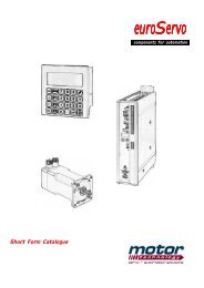
Short FormCatalogue2005Short Form CatalogueDrive ElectronicsElectric <strong>Motor</strong>sMotion ControlFeedback DevicesPower TransmissionMechanical ActuatorsRev. 3/09
<strong>Motor</strong> <strong>Technology</strong> <strong>Ltd</strong> – control in motion.comServo drives – Metronix ServoCommander TM commissioning software <strong>for</strong> ARS 2000The Metronix ServoCommander is a user-friendlyWindows based commissioning tool, to enable theswift adoption of the drive to your motor andapplication.What differentiates ServoCommander from otherdrive commissioning tools is that it has beendesigned to allow the set-up with any motor.The 1 st Commissioning wizard gives the user, evena novice, the tools to get up and running in theshortest possible time.The software features automatic motoridentification, which recognises the number ofmotor poles, winding resistance and inductanceduring the process.The same software plat<strong>for</strong>m is used <strong>for</strong> the entireARS range, whether you are operating asynchronous, linear or torque motor.FeaturesConfigure yourapplicationassisted by theintuitive menus,supportinggraphics andOnline help.Start the “1 stcommissioning”wizardPlain text andgraphic iconsare used toguide you.• ServoCommander TM softwaretool with commissioningwizard• Commission any motor inminutes• Automatic recognition of theconnected ARS drive• Automatic motor phasing• Determines motor poles,winding resistance andinductance• Simultaneous indication ofreference values and actualvalues• Offline parameter setting• Display of values incustomer-specific units• Graphic display of structures• Extensive online help• Excellent navigationproperties provided byGraphic buttons• Context-sensitive windows• 4 channel oscilloscopefunction• Multilingual• Loading and saving ofparameter setsA cut down version of the ServoCommander TM software is also available <strong>for</strong> the DIS-2 24/48V DC servo drive.The above is sample in<strong>for</strong>mation on the product range. Please contact us <strong>for</strong> a full brochure . . .Doc. MT-sfc-3/09 Call 0161 217 7100 or email us at info@controlinmotion.com <strong>for</strong> further details Page 5
<strong>Motor</strong> <strong>Technology</strong> <strong>Ltd</strong> – control in motion.comServo drives – Metronix DIS-2, <strong>for</strong> low voltage AC and DC servo motorsThe DIS-2 is a fully digital AC servo controller <strong>for</strong>three-phase synchronous and PM DC motors with asupply voltage of 24 to 48 V DC.• Cost optimised especially <strong>for</strong> seriesapplications• Compact design with one PCB• Direct mounting on the motor, or chassis• High protection class up to IP67 when fittedto a motor• Operation in industrial area without externalEMC components• Full 4Q operation with continuous control• Integrated CAN-Bus Interface with DSP402• Easy coupling to PLC via I/O or field-busThe DIS-2 can be used as a torque, speed orposition controller with synchronization. It iscontrolled via the CAN bus or a serial interface.Programming and diagnosis are possible via the RS232 orCAN bus port.The setup software DIS-2 ServoCommander allows a fastand very user-friendly controller configuration on the PC.With this software it is also possible to set up the nominalcurrent to 15A and maximum current to 40A (8/14A on DIS-224V unit).In positioning mode, 64 position sets can be stored asabsolute or relative point-to-point values. It is also possible toteach-in up to 32 positions by moving to the real position.The “Interpolated position mode” is also integrated via CANbus. For reference positioning it is possible to use a digitalinput. The set point assignment can be realised either via thebus or via two analogue +/-10 V nominal inputs.An analogue output 0…+10 V is programmable to one of thedifferent set points or actual values. The last 6 errors arepermanently stored in an error memory.The universal encoder interface supports the most motorfeedback standards.Technical Data DIS-2 24/8 (MDRM-H) DIS-2 48/10 (MDRM48)Supply voltage 24 VDC; ± 10% 24 to 48 VDC; ± 20%Control voltage 24 VDC; ± 10% 24 VDC; ± 20%Rated current I Rate 8 A RMS 15 A RMSMaximum current I Max <strong>for</strong> 2 sec 14 A RMS 40 A RMSRated power P Rate Approx. 120W 750VA at 48V DCMaximum power P Max Approx. 180W 1500VA at 48V DCClock frequency f PWM 10 kHz 10 kHzHousing temperature 0° to +70°C 0° to +65°CEnclosure IP00 IP54, prepared <strong>for</strong> IP67Dimensions in mm (W x H x D)Dimensions in mm (W x H x D)Encoder evaluationInterfacesInputs (maximum)Outputs (maximum)<strong>Motor</strong> Flange versionDiameter 65mm, height 40mmDIN-Rail versionW = 65mm, H = 78mm, D = 68,5mm(without connector)ResolverAnalogue hall sensorsRS 232CAN bus to DSP402 / DS3012 x DIN 24V, ENABLE & DIR2 x AIN, 0…10V, 12 Bit2 x DOUT, 24V1x OUT = Drive Ready1 x ERR = Error stateAMP Plug version110 (with Plug 126) x 56 x 80Phoenix Plug version112 (with Plug 120) x 56 x 80Resolver, analogue hall sensors,Digital six-step-hall sensors with blockcommutation,SinCos encoder with HIPERFACERS 232, CAN bus,Optional ProfiBus8 x DIN, 24V2 x AIN, ±10V differential, 12 Bit3 x DOUT, 24V1x brake, 24V, 500 mA1 x AOUT, 0.05..10V, 8 BitAdditional incremental encoder output <strong>for</strong>synchronizationThe above is sample in<strong>for</strong>mation on the product range. Please contact us <strong>for</strong> a full brochure . . .Page 6 Call 0161 217 7100 or email us at info@controlinmotion.com <strong>for</strong> further details Doc. MT-sfc-3/09
<strong>Motor</strong> <strong>Technology</strong> <strong>Ltd</strong> – control in motion.comServo drives – MS / MTS, <strong>for</strong> DC servo motorsBased on the MS series 19’ Euro-card drives, theMTS series of drives is supplied in a stand-alonehousing incorporating the power supply and regencircuitry.The module can be back panel mounted andtermination is to plug-in terminals. Units are suitable<strong>for</strong> motors up to 200Vdc with current ratings up to14A continuous.Features• Compact design• Integral power supply and regen circuit• Removable personality module• No noise (20kHz switching frequency)• Differential speed command (+/-10V)• Tachometer, armature and encoder feedbackpossible• CE con<strong>for</strong>mity• Acceleration and deceleration rampsAdjustments• Dynamic gain• Derivative and integral adjustment• Offset• Fine speed potDiagnostics LEDs• Drive-ok• Over-current• Over temperature• I 2 t• Tachometer lossRangeModelSupply Voltage(Vac)<strong>Motor</strong> Voltage(Vdc)Nominal Current(A)Peak Current(A)MTS 60-4/8 20 ... 40 27 ... 54 4 8MTS 60-8/16 20 ... 40 27 ... 54 8 16MTS 60-10/20 20 ... 40 27 ... 54 10 20MTS 60-14/28 20 ... 40 27 ... 54 14 28MTS 140-4/8 35 ... 95 47 ... 122 4 8MTS 140-8/16 35 ... 95 47 ... 122 8 16MTS 140-10/20 35 ... 95 47 ... 122 10 20MTS 140-14/28 35 ... 95 47 ... 122 14 28MTS 200-4/8 52 ... 145 70 ... 200 4 8MTS 200-8/16 52 ... 145 70 ... 200 8 16MTS 200-10/20 52 ... 145 70 ... 200 10 20MTS 200-14/28 52 ... 145 70 ... 200 14 28The above is sample in<strong>for</strong>mation on the product range. Please contact us <strong>for</strong> a full brochure . . .Page 8 Call 0161 217 7100 or email us at info@controlinmotion.com <strong>for</strong> further details Doc. MT-sfc-3/09
<strong>Motor</strong> <strong>Technology</strong> <strong>Ltd</strong> – control in motion.comStepper drives + motorsHigh reliability and per<strong>for</strong>mance, compact size andlow cost are the requirements around which the DSrange of stepper motor drives have been designed.Using the latest electronic components and SMDtechnology it has been possible to produce a highpower driver in a compact and smart case easy andquick to install on a DIN rail.The connection to the motor, with the logical signalsand to the power supply is through three differentcoloured terminal blocks; each one of them isremovable, numbered and suitable <strong>for</strong> 2,5mm 2 wiresize.A wide range of setting options allows the drives tobe configured <strong>for</strong> different motors and applications.<strong>Motor</strong> phase current, step resolution, etc can all beset in the graphic software UDP Commander whichruns under Windows.Features• Resolution up to 25,600 step/rev• STEP frequency to over 300kHz• Wide power range up to 10A, 240Vdc• Compact DIN-rail mounted unit• Easy to install using removable terminal blocks• Configuration via Windows based softwareNEW - DS30 range with integrated controller!Technical Data DS1044 DS1048 DS1073 DS1076 DS1078 DS1084 DS1087 DS1098Power supply voltageVdc20…50 20…50 24…90 24…90 24…90 45…160 45…160 45…240Phase current, Arms(adjustable)1…4 3…8 0.8…3 2…6 4…10 2…4 4…8.5 4…10Dimensions, mm(H x W x D)101x18x119 101x35x119 101x18x119 101x35x119 101x35x119 101x35x119 101x35x119 101x35x119The M-series stepper motors are characterised byhigh torque, compact size and low rotor inertia.The torque range covers from 0.28Nm up to 21Nm,with a phase current of between 0.6A and 12A.These motors have a step angle of 1.8° and areoptimised <strong>for</strong> the micro-stepping which ensures anaccurate and smooth movement of the shaft.Our drives are the natural companion <strong>for</strong> this familyof motors and when used together they allow highpositioning precision and repeatability to beachieved.All the models are provided with a standard NEMAflange that makes installation easy, both on existingsystems and on new applications. The motors withtorque over 1.5Nm have the shaft with single ordouble plane face <strong>for</strong> a simple and safe fixing. Onrequest we can provide versions with keyed shaft.Features• NEMA frame sizes 17, 23, 34 and 43• Torque range from 0.28 to 21Nm• Bipolar operation, size 34 and 43 also unipolar• Low inertia• Optional second shaft and custom windingsTechnical DataTorqueRange (Nm)Flying Lead coresPhase Currentmin/max (A)<strong>Motor</strong> Length (mm)Shaft diameter (mm)NEMA17 0.28 … 0.5 4 1.3 … 1.7 34 … 48 5NEMA23 0.55 … 3.4 4 0.62 … 6 41 … 112 6.35NEMA34 3.1 … 12.1 8 5.6 … 12 63 … 150 14NEMA 43 14.4 … 21 8 12 115 … 150 19The above is sample in<strong>for</strong>mation on the product range. Please contact us <strong>for</strong> a full brochure . . .Doc. MT-sfc-3/09 Call 0161 217 7100 or email us at info@controlinmotion.com <strong>for</strong> further details Page 9
<strong>Motor</strong> <strong>Technology</strong> <strong>Ltd</strong> – control in motion.comServo drives - Servostar 300The new Servostar 300 range is a furtherdevelopment of the well-established Servostar 600drive, offering higher per<strong>for</strong>mance in a smallerpackage.The Servostar 300 offers full single axis control withon-board power supply, filters and ballast resistor.They also features a RS232 port, CANopen interface(Profibus-DP, DeviceNet and Sercos optional), control<strong>for</strong> rotary and linear motors and feedback fromresolver, high-resolution encoders or hall-sensors.The drives also feature an integrated position controller<strong>for</strong> simple motion tasks. In addition the drives canaccept a pulse / direction (stepper controller) input <strong>for</strong>added flexibility. Master / slave and electronic gearingis also standard.Options include the AS-Enable, restart lock <strong>for</strong> additionalsafety and the drive is also available with the TrioMC302-K Motion Coordinator (see page 4).Technical Data Dim 303 306* 310* 341 343* 346*Rated supply voltage(+/-10%)Vac 3 x 115V to 230V 3 x 208V to 480VRated installed power <strong>for</strong> S1operationkVA 1.2 2.4 4 1.4 3.3 5Rated DC link voltage Vdc 145 … 360 560 … 675Rated output current (rms value, ± 3%) / Peak output current (max. 5s, ± 3%)At 1 x 110V mains voltage Arms 3 / 5 3 / 5 3 / 5 - - -At 1 x 230 / 240V mainsvoltageArms 3 / 9 4 / 9 4 / 9 - - -At 3 x 115V mains voltage Arms 3.5 / 9 8 / 15 10 / 20 - - -At 3 x 235V mains voltage Arms 3 / 9 6 / 15 10 / 20 2 / 4.5 5 / 7.5 6 / 12At 3 x 400V mains voltage Arms - - - 1.5 / 4.5 4 / 7.5 6 / 12At 3 x 480V mains voltage Arms - - - 1.5 / 4.5 3 / 7.5 6 / 12Continuous internal regenpower (RBint)W 40 40 40 40 40 40Continuous external regenpower (RBext)kW 0.25 0.25 0.25 to 0.75 0.4 to 1.5 0.4 to 1.5 0.4 to 1.5Peak regen power (PRext),max.kW 1.5 to 3 1.5 to 3 3 7 to 9.5 7 to 9.5 7 to 9.5* requires fan unitDimensionsConnectivity options(in mm)The above is sample in<strong>for</strong>mation on the product range. Please contact us <strong>for</strong> a full brochure . . .Page 10 Call 0161 217 7100 or email us at info@controlinmotion.com <strong>for</strong> further details Doc. MT-sfc-3/09
<strong>Motor</strong> <strong>Technology</strong> <strong>Ltd</strong> – control in motion.comServo drives - Servostar 600The Servostar 600 combines a very fast 62microsecond servo loop with feedback from either aresolver or sine/cosine encoders enabling tightpositional accuracy and speed control equivalent to ananalogue drive.The Servostar 600 drives are compact (14kVAServostar 620 measures only 325 x 70 x 265mm) andare suitable <strong>for</strong> 300mm switch-gear cabinets. Therange has now been extended to 50kVA continuous.They are easy to install, with only two mounting screwsrequired, and all internal connections are of the plugin-and-screwtype. Additionally, all CE filters areintegrated on the range up to 14kVA.With approx. 20,000 units produced per year, theServostar 600 is an industry proven drive, offeringreliability and cost-effectiveness.Servostar 600 has been designed <strong>for</strong> simple operationand is supplied with powerful Motionlink and Windowssoftware that has an oscilloscope function <strong>for</strong> displayingcurrent and speed data.The front panel is user-friendly with a straight<strong>for</strong>ward twokeypad and a three-character LED display.Technical DataData Dim 601 603 606 610 610-30 614 620 640 670Rated supply voltage (3ph) Vac 3 x 208V(-10%) ... 480V(+10%), 50 ... 60HzRated installed power <strong>for</strong> S1operationkVA 1 2 4 7 7 10 14 30 50Rated DC link voltage Vdc 260 ... 675Rated output current(rms value, ± 3%)Arms 1.5 3 6 10 10 14 20 40 70Peak output current30Arms 3 6 12 20(max. 5s, ± 3%)(2sec)28 40 80 140Continuous internal regenpower (RBint)W 80 80 200 200 200 200 200 - -Max. continuous externalregen power (RBext)kW 0.5 0.5 1.5 1.5 1.5 1.5 1.5 6 6Peak external regen power(PRext), max.kW 21 21 21 21 21 21 21 45 70Highlights• high speed current and velocity loops• Encoder emulation - incremental (ROD426, dec./bin.) or absolute (SSI,Gray/Binary)• Feedback from resolver (standard) or high resolution sine-cosineencoder (EnDat or HiperFace)• Interface <strong>for</strong> stepper controllers integrated (PULSE CONNECT)• CANopen integrated• Fully programmable via RS232 interface• Operation from a PC via Windows software• Operation with 2 keys on the amplifier, with status monitoring via LEDdisplay• CE- / UL- con<strong>for</strong>mity• Up to 180 high resolution motion tasks with definable S-curve profile,In-position window and 16 different homing routines• Open architecture - ProfiBus L2/DP, DeviceNET, Ethernet, I/Oextensionboard, FireWire 1394 and SERCOSDimensionsDimensions (mm) <strong>for</strong>:614 - h 275 / w 100 / d 265620 - h 275 / w 120 / d 265640/670 - h 345 / w 250 / d 300The above is sample in<strong>for</strong>mation on the product range. Please contact us <strong>for</strong> a full brochure . . .Doc. MT-sfc-3/09 Call 0161 217 7100 or email us at info@controlinmotion.com <strong>for</strong> further details Page 11
<strong>Motor</strong> <strong>Technology</strong> <strong>Ltd</strong> – control in motion.comServo motors - SBL-T series AC brushlessThe SBL-T range of three-phase AC brushlesssynchronous servomotors offer excellent per<strong>for</strong>mancecombined with low-cost.The motors have low inertia, good power density andIP65 protection. The motors have a 6-pole winding andare fitted with a 2-pole resolver.The SBL-T motors are available with various connectorconfigurations, shaft-seals and key / key-ways.A wide range of feedback options is available includingincremental, HiperFace and EnDat encoders.The motors can be supplied with holding brakes,IP rating up to IP67 and vacuum rated. Specialrequirements such as encoders / adapters, specialwindings or short motors are also possible.Technical DataA range of low voltage 24, 48 and 60V motors areavailable on request.For a full set of in<strong>for</strong>mation, please request a copy of ourSBL-H/T/TC motor catalogue.DimensionsTypeSBL-T1SBL-T2SBL-T3SBL-T4SBL-T5SBL-T6SBL-T7SBL-T8Stall / NomTorqueMo / Mn0.1 / 0.090.2 / 0.180.3 / 0.270.2 / 0.190.4 / 0.360.6 / 0.550.8 / 0.720.95 / 0.85NominalSpeednNStall Current300VStall Current600VNm RPM A A kgcm 20.580.066000 0.97 na 0.080.950.10.59 0.47 0.060.93 0.54 0.084500 1.21 0.73 0.111.56 0.91 0.131.82 1.15 0.180.65 / 0.61.3 / 1.151.9 / 1.62.5 / 2.153 / 2.52.6 / 2.33.9 / 3.35.3 / 4.67.5 / 6.49.5 / 8.56.6 / 5.710.5 / 8.813.5 / 1117 / 14.522 / 1713.5 / 1319 / 1722 / 1929 / 2435 / 2627 / 2132 / 2340 / 2640 / 3068 / 5093 / 70115 / 853000300030003000300030003000200020001.061.672.503.003.503.154.806.509.1011.37.712.217.421.225.614.620.522.931.3na28.132.844.0na0.651.011.421.802.081.922.904.104.806.64.57.311.211.416.48.211.514.617.223.516.019.024.721.839.933.142.1Inertia J A B D E H K K1 P0.50.650.921.41.51.92.252.654.146.054627.39.511.713.118.721.532.8463639457611415319025 32 6 16 3740 63 9 24 5580 100 14 30 8895 115 19 40 105130 165 24 50 142180 215 24 50 190180 215 28 58 190230 265383842428080110110240819611198113128143158109127145163181146161176221276185219236270304201235252310378242257287310378446514111126141131146161176191142160178196214178193208253308228262279313347254288305356424296311341378446514582na74115130188250250300For dimensions refer to the drawing on page 13.The above is sample in<strong>for</strong>mation on the product range. Please contact us <strong>for</strong> a full brochure . . .Page 12 Call 0161 217 7100 or email us at info@controlinmotion.com <strong>for</strong> further details Doc. MT-sfc-3/09
<strong>Motor</strong> <strong>Technology</strong> <strong>Ltd</strong> – control in motion.comServo motors - SBL-H series pole-wound AC BrushlessThe SBL-H range of three-phase AC brushlesssynchronous servomotors offer excellent per<strong>for</strong>mancecombined with low-cost.The motors have very low inertia, high power densityand IP65 protection. The motors have a 8-pole windingand are fitted with a 2-pole Resolver.The SBL-H motors are available with various connectorconfigurations, shaft-seals and key / key-ways.A wide range of feedback options is available includingincremental, HiperFace and EnDat encoders.The motors can be supplied with holding brakes,IP rating up to IP67 and vacuum rated.For a full set of in<strong>for</strong>mation, please request a copy of ourSBL-H/T/TC motor catalogue. Special requirementssuch as encoders / adapters, special windings or shortmotors are also possible.Technical DataDimensionsTypeSBL-H2SBL-H3SBL-H4SBL-H5Stall / NomNominal Stall CurrentTorqueSpeed nN 300VMo / Mn0.26 / 0.240.53 / 0.450.74 / 0.670.95 / 0.840.95 / 0.861.9 / 1.63.25 / 2.9Stall Current600VNm RPM A A kgcm 20.7 0.7 0.0645001.26 0.73 0.081.66 0.95 0.12.09 1.31 0.124.2 / 3.14.1 / 3.26.3 / 4.68.6 / 6.111.6 / 8.414.9 / 10.918.7 / 14.327.3 / 213000300030001.472.754.254.869.211.217.320.227.932.41.321.662.452.953.44.756.410.312.516.419Inertia J A B D E H K K1 P0.50.71.11.51.72.63.56.88.31115.340 63 9 20 5580 100 14 30 8695 115 19 40 98130 165 24 50 1426782971129611415018612915918917220023029010512013515013815619222817020023022425228234274115130188DrawingøAøDBPE K (K1 with Brake) HThe above is sample in<strong>for</strong>mation on the product range. Please contact us <strong>for</strong> a full brochure . . .Doc. MT-sfc-3/09 Call 0161 217 7100 or email us at info@controlinmotion.com <strong>for</strong> further details Page 13
<strong>Motor</strong> <strong>Technology</strong> <strong>Ltd</strong> – control in motion.comServo <strong>Motor</strong>s - AC Brushless with integrated Servo Drive up to 2.3NmThe HDM82 range of drive-integrated three-phase ACBrushless synchronous servomotors offer excellentper<strong>for</strong>mance combined with low-cost and simplifiedinstallation.The motors have low inertia, good power density andIP65 protection. The motors have a 8-pole winding andare fitted with a 2-pole Resolver.Fitted to the motor is the Metronix DIS-2 48V servodrive (full details on page 8). The range covers 0.59 to2.3Nm and speed ranges between 1000 and 5000rpm.The motors can operate autonomous with only a 24-48Vdc supply.The motors are available with the standard 2-poleResolver, HiperFace absolute encoders and Rencoincremental encoders with commutation tracks.As standard the motors feature keyed-shaft, industrystandard shaft and flange sizes, integrated temperaturesensor and Class F insulation. An optional holding brakeis available.Operating Modes• Autonomous• PLC control via I/O• RS232 serial communication• CANbus interface• Profibus DP (optional)• EtherCAT (optional)Technical DataTypeCont. Stall Cont. Stall Nominal Torque Peak Peak LengthTorque Mo Current Io Speed nN Constant KM Torque Mo Current Imax L / L1Nm A RPM Nm/A Nm A mmHDM82-A8-7S 0.59 7.2 5000 0.081 2.0 42 139 / 179HDM82-A8-11.S 0.72 5.4 3000 0.13 2.2 29 139 / 179HDM82-C8-14S 1.2 7.3 2400 0.17 3.9 42 157 / 197HDM82-E8-19S 1.5 6.9 2000 0.22 5.3 42 175 / 215HDM82-J8-30S 2.3 6.6 1000 0.35 8.4 42 211 / 251Dimensionsø80 (h7)ø100ø112110ø14 (j6)30 L (L1 with Brake)82The above is sample in<strong>for</strong>mation on the product range. Please contact us <strong>for</strong> a full brochure . . .Page 14 Call 0161 217 7100 or email us at info@controlinmotion.com <strong>for</strong> further details Doc. MT-sfc-3/09
<strong>Motor</strong> <strong>Technology</strong> <strong>Ltd</strong> – control in motion.comServo motors - EX series AC brushless, <strong>for</strong> explosive atmospheresEX servomotors are group II, category 2, explosionproofapparatus designed to operate in explosiveatmospheres in accordance with EN 50014 standard.These servomotors are certified according to ATEX94/9/CE directive and are available as 2 models:Gas version• II2 G EEx d IIB T4, motor <strong>for</strong> gaseousatmospheres. This motor is not fitted with a lip sealat the customer shaft end.Gas/Dust version• II2 GD EEx d IIB T4, motor <strong>for</strong> dusty, gaseousatmospheres. This motor is fitted with a lip seal atthe customer shaft end.• "d" explosion-proof equipment in accordance withATEX 94/9/CE directive• Extremely compact, very well suited to spray paint• High dynamic level• Built-in resolver with no need <strong>for</strong> supplementaryencoder• Bearings greased <strong>for</strong> life, no maintenancenecessary<strong>Motor</strong>230V supplyTorque atlow speedNmCurrent atlow speedÂMaximumspeedtr/min<strong>Motor</strong>400V supplyTorque atlow speedNmCurrent atlow speedÂMaximumspeedtr/minEX310EAP 1.75 1.7 2300EX310EAK 1.75 3.1 4000EX420EAP 3.5 3.5 2300EX420EAJ 3.5 6.0 4000EX430EAJ 4.8 6.5 3200EX430EAF 4.8 8.2 4000EX620EAO 6.6 7.4 2500EX630EAI 10.4 14.2 3000EX820EAR 14 13.5 2200EX820EAL 14 21.7 3600EX840EAJ 24.5 23.4 2200EX860EAD 35 39.9 2600EX310EAP 1.75 1.7 4000EX420EAV 3.5 1.7 2000EX420EAP 3.5 3.5 4000EX430EAP 4.8 3.5 3000EX430EAL 4.8 4.7 4000EX620EAO 7.0 7.8 4300EX630EAY 10.4 7.8 2900EX630EAN 10.4 10.6 4000EX820EAW 14 7.9 2200EX820EAR 14 13.5 3600EX840EAQ 24.5 12.5 2100EX840EAK 24.5 20.8 3300EX860EAJ 35 22.4 2600*EX4 DIMENSIONS (MM)*EX8 DIMENSIONS (MM)*Please note that the data <strong>for</strong> the EX4 and EX8 motors is preliminary.The above is sample in<strong>for</strong>mation on the product range. Please contact us <strong>for</strong> a full brochure . . .Doc. MT-sfc-3/09 Call 0161 217 7100 or email us at info@controlinmotion.com <strong>for</strong> further details Page 15
<strong>Motor</strong> <strong>Technology</strong> <strong>Ltd</strong> – control in motion.comServo motors - <strong>Motor</strong> Power Company SKA direct drive rotaryFeaturing an excellent nominal and peak torquecapacity plus high acceleration and decelerationvalues, the SKAddr direct drive servomotors achieveefficiencies and precision positioning that are difficult toobtain with conventional systems.Natural evolution of direct coupling between the motorand driven load, the conventional components of thekinematic chain have been totally eliminated fromthese servomotors.Besides eliminating backlash and mechanical elasticityin the drive transmission, this type of configurationdrastically speeds up servicing work and lowersmaintenance costs while achieving appreciable energysavings through improved overall efficiency.Two versions are available <strong>for</strong> the SKAddr series:• Frameless, with the stator and rotor parts alone• Power Pack, fully assembled and housed versionincludes the SKAddr torque motor with mountingflange, bearings and transducer, aluminium covercase and specific connectionsFeatures• ‘Multi-pole’ permanent magnet brushlesssynchronous servomotor• 1.9 Nm to 770 Nm stall torque• Thermal protector (clixon)• Class F insulation• IP65 protection (PP version)• Wide range of transducers including, Resolver, Halleffectsensors, incremental encoders, sine / cosineencoders, tape encoders, magnetic encoders• Versions with hollow or solid shaft• Supply voltage 145 to 460 VacTechnical Data Units SKA DDR090 SKA DDR148 SKA DDR245 SKA DDR335 SKA DDR430External Diameter (A) (mm) 110 180 290 390 470Hole Diameter (B) (mm) 38 78 145 235 320Length (H)(mm)6090120Number of Poles 14 14 28 42 56Stall Torque(Nm)1.93.24.360901201508.313.718.723.3Speed Range (rpm) 1700÷300 1200÷150 800÷90 500÷50 300÷50609012015042678810960901201501801001602102603006090120150180210237368479580677770Power Pack componentsDimensions (frameless stator part)The above is sample in<strong>for</strong>mation on the product range. Please contact us <strong>for</strong> a full brochure . . .Page 16 Call 0161 217 7100 or email us at info@controlinmotion.com <strong>for</strong> further details Doc. MT-sfc-3/09
<strong>Motor</strong> <strong>Technology</strong> <strong>Ltd</strong> – control in motion.comServo motors - <strong>Motor</strong> Power Company SKA direct drive linearThe SKAddl iron core synchronous linear servomotorshave a high <strong>for</strong>ce density and features high-energyNdFeB magnets, making them ideal <strong>for</strong> applicationsthat need high reversal frequencies and positioningcapacities.The backlash and mechanical elasticity found inconventional systems have been completelyeliminated.Higher overall efficiency also achieves lower energyconsumption, leading to cost efficiencies.The SKAddl series permits a very wide range ofconfigurations along the X, Y and Z-axes, such asvertical and horizontal gantries and cantilever systems.SKAddl Compact combines the per<strong>for</strong>mance of directdrive technology (i.e. direct connection to the drivenload) with easy assembly in a complete, plug-and-playsystem housed in an extruded aluminium body.framelesscompactThe linear technology of the SKAddl series, now also readyassembled in an extruded aluminium body.Features• Power supply voltage: 145 Vac, 230 Vac, 460 Vac• Transducers: sin-cos encoders, TTL (optical andmagnetic)• Plug and play structure made of aluminium. Thetemperature sensor, linear ball bearings, bellows,encoder, cables and cables carrier are alreadyincluded in the motorTechnical DataServomotor type Units 55HX 55HS 55HM 75HS 75HM 100HS 100HM 125HS 150HSPeak <strong>for</strong>ce (N) 450 825 1650 1980 2970 3600 4800 6000 7200Continuous <strong>for</strong>ce (N) 150 275 550 660 990 1200 1600 2000 2400Maximum speed (m/s) 5 5 5 5 5 5 5 5 5Maximum theoreticalacceleration(m/s 2 ) 321 275 240 206 247 200 192 193 194DimensionsCoil length (mm) 180 180 350 350 510 535 695 695 695Coil width (mm) 55 80 80 100 100 130 130 155 180Coil height (mm) 47.5 47.5 47.5 51 51 51 51 51 51Coil weight (Kg) 1.4 3 6.9 9.6 12 18 25 31 37Magnet track width (mm) 60 90 90 120 120 140 140 175 200Magnet track height (mm) 15 15 15 17 17 17 17 17 17Magnet track weight (Kg/m) 4.8 8.5 8.5 13 13 13 15.7 19 22COMPACT version YES YESApplication examplesThe above is sample in<strong>for</strong>mation on the product range. Please contact us <strong>for</strong> a full brochure . . .Doc. MT-sfc-3/09 Call 0161 217 7100 or email us at info@controlinmotion.com <strong>for</strong> further details Page 17
<strong>Motor</strong> <strong>Technology</strong> <strong>Ltd</strong> – control in motion.comMotion Control - Trio Motion <strong>Technology</strong>All controllers use the same TrioBASIC command set andare programmed and set-up using the industry-provenMotionPERFECT software.With a dedicated in-house design team, customers canalways be assured of the highest quality products.The extensive product range covers all manner ofapplications from simple stepper-motor based requirementsto high-end multi-axis servo driven systems.Trio Motion <strong>Technology</strong> has been manufacturingand distributing high-quality motion control productssince 1987.The products can be found in virtually every servoand stepper application.A wide range of controller accessories are availableincluding HMIs, encoder interface boards, CAN I/Omodules, Fieldbus interfaces, etc.<strong>Motor</strong> <strong>Technology</strong> enhances this offering with a wideselection of compatible servo and stepper drives andmotors, and ancillary mechanical components such aslinear actuators, gearboxes, couplings, etc.MC302X» 2 axis stepper or 1.5 servo» Compact 94w x 56d x 105h.» Easy DIN rail mounting» Multi-tasking TrioBASICsystem, maximum 3 tasks» Motion Perfect ApplicationDevelopment Software» CAN Networking» Individual Status LEDsPCI 208» Short PCI Card» 2-8 Axes Stepper/Servo» High Speed Dual Port RAM» OCX Software Componenteases application software» Opto-isolated IO (20 In/10Out)with CAN I/O expansion» 100 Way MDR Connector» 2 CAN InterfacesMC206X» 1-4 axis Stepper/Servo» Compact 107h x 182w x53d on DIN-rail» Pre-emptive multi-taskingTrio BASIC, max. 8 tasks» Motion Perfect ApplicationDevelopment Software» CAN Networking» Individual Status LEDsEuro205x» High per<strong>for</strong>mance, low cost 1-4Stepper/Servo axes» Up to 8 axes using SERCOS orCANopen» Linear, circular and helicalinterpolation» Electronic clutches, gears andcams» Motion Perfect applicationdevelopment software» 160mm x 100mm Eurocard» Registration inputsMC224» Interpolates up to 24 axesin any combination.» Advanced Multi-tasking TrioBASIC with up to 14simultaneous processes.» 150Mhz, 32bit FP-DSP» 1 Mbyte application memory» 256k word TABLE memory» USB Interface built-in» Memory Stick Interface» Compatible with all TrioDaughter Board interfaces.» Fully integrates withMotionPerfect 2MC302-K» 95mm x 140mm x 20mm» Plug-in card <strong>for</strong>Servostar S600/S300» Forward/Reverse Limit, Datum,Feedhold Assignable controlinputs» Pre-emptive multi-tasking TrioBASIC» Virtual axis <strong>for</strong> movesuperimposition» 1.5 Axes: Servo +synchronisation encoder» 12 opto-isolated inputs» 8 opto-isolated outputs» 2 x 16 bit analogueThe above is sample in<strong>for</strong>mation on the product range. Please contact us <strong>for</strong> a full brochure . . .Page 18 Call 0161 217 7100 or email us at info@controlinmotion.com <strong>for</strong> further details Doc. MT-sfc-3/09
<strong>Motor</strong> <strong>Technology</strong> <strong>Ltd</strong> – control in motion.comMotion Control – Metronix / Trio MC2000The MC 2000 motion control module <strong>for</strong> the ARS2000 servo drive range enables coordinated motion<strong>for</strong> up to 4 servo axes.Complex motion control requirements can be realisedquickly and efficiently, such as:• Electronic CAM and Gearing• Synchronised Axes• Point-to-point Positioning• Interpolated AxesThe MC 2000 is simply plugged-in to the ARS 2000drive. The controller then acts as the Master over theCANopen DS 402 field-bus controlling one, two,three of four servo drives.Additionally an external encoder can be attacheddirectly to the drive to give a further ½ axis of control.The extensive I/O facilities of the ARS 2000 drive canbe utilised in the controller. Furthermore the systemcan be extended using the plug-in I/O module EA88or CAN I/O.Compact• Controller plugs directly into the drive• Coordination of up to 4 servo axes• Easy cabling via CANbusEasy• Simplified application programming with theestablished Trio Motion software ‘Motion Perfect’• Easy generation of complex motions such as CAM,gearing or multi-axis interpolation• Clear cabling through the use of drive-internalinterfaces and fast Dual Port RAMSystem integrationHMIs can be connected to the controller via the RS485interface. I addition the integrated RS232 port provides thelink to the Trio ‘Motion Perfect’ multi-tasking softwaredevelopment environment.Fast• 1ms cycle time with up to 4 axes• Short commissioning times using the Trio‘Motion Basic’ programming language, withextensive command set• High-speed sampling input <strong>for</strong> fast actualvalue capture and evaluation.Technical DataServo loop time 1000µs EMC Standard EN 61800-3Number of Axes 8 (4 servo, 1 encoder, 3 virtual) Current Usage From the drive 150mA / 5vSerial Connections 1 x RS232 <strong>for</strong> programming1 x RS485 <strong>for</strong> HMIInput FunctionsPositive and negative limits, Homingand Feed holdCAN Ports1 x Remote Drives 1MBaud1 x Remote I/O 500KBaudExpansion PortsExternal I/O ModuleService Module (via ARS 2000)Multi-Tasking2 x Fast tasksAdditional Interface via Incremental encoder / stepper5 x Normal tasksAnalogue Inputs 3 @ 0-10V, via ARS 2000- 1 x 16bit- 2 x 10bitServo DriveUser Memoryoutput (line driver)512kBytes- 8 x digital IN- 8 x digital OUTAnalogue Outputs Two 9-bit via ARS 2000 Table Memory 32000 ValuesDigital Inputs 5 x 24V via ARS 2000 Dimensions (L x B x H) 92 x 65 x 19mmDigital Outputs 3 x 24V via ARS 2000 Temperature Range 0-50°CThe above is sample in<strong>for</strong>mation on the product range. Please contact us <strong>for</strong> a full brochure . . .Doc. MT-sfc-3/09 Call 0161 217 7100 or email us at info@controlinmotion.com <strong>for</strong> further details Page 19
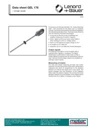
<strong>Motor</strong> <strong>Technology</strong> <strong>Ltd</strong> – control in motion.comEncoders - Lenord+Bauer GEL207 / 208, magnetic incrementalThe GEL207 / 208 range of magnetic incrementalencoders offer a reliable, robust and flexiblealternative to conventional optical devices. Both unitsoffer a wide selection of pulse numbers, outputsignals and additional protection options.The GEL207 is a servo-mounted unit suitable <strong>for</strong>mounting to a wide range of servo, AC and DCmotors.The GEL208 is a flange-mounted unit and features alarge diameter shaft 10mm, which is suitable <strong>for</strong> usewith pulleys, measuring wheels etc.Features• Up to 136,192 ppr• Optional vibration and humidity protection,condense-water outlet• IP65 rating as standard• Suitable <strong>for</strong> speed up to 10,000rpmOther productsMagnetic Incremental Encoders - Up to 273,408 ppr.Hollow-shaft Encoders - Up to 266,240 ppr.Absolute Encoders - Single / multi-turn up to 65536x4096.Linear scales - Absolute up to 7.5m.MiniCoder - Miniature incremental encoders in kit <strong>for</strong>m.Technical DataGEL 207 / GEL208Standard pulse numbersOutput signals50, 60, 90, 120, 125, 150, 180, 200, 250, 256, 300, 360, 400500, 512, 600, 720, 750, 800, 900, 1000, 1024, 1200, 1250, 15001800, 2000, 2048, 2500, 3000, 3600, 4000, 4096, 5000T = Supply 5V, Output Signal 5V quadrature with inverseU = Supply 10…35V, Output Signal 5V quadrature with inverseV = Supply 10…35V, Output Signal 10…35V two channelX = Supply 10…35V, Output Signal 10…35V with inverseMaximum operating rpm10,000rpmMaximum output frequency200kHzOperating temperature range0…+70°C standard (optional –20…+85°C)Protection classIP65WeightApprox. 0.5kgRotor inertia 7 x 10 -5 kgm 2GEL 207 GEL 208The above is sample in<strong>for</strong>mation on the product range. Please contact us <strong>for</strong> a full brochure . . .Page 20 Call 0161 217 7100 or email us at info@controlinmotion.com <strong>for</strong> further details Doc. MT-sfc-3/09
<strong>Motor</strong> <strong>Technology</strong> <strong>Ltd</strong> – control in motion.comEncoders - Lenord+Bauer GEL235, magnetic absoluteThe GEL 235 range of magnetic absolute encodersoffer a reliable, robust and flexible alternative toconventional optical encoders, making them suitable<strong>for</strong> harsh environments previously consideredunsuitable <strong>for</strong> such high precision devices.The GEL 235 is able to achieve 16-bit single-turnresolution with a precision better than 0.1°, a recordfigure <strong>for</strong> magnetic absolute encoders. The GEL235’s multi-turn variant achieves 28 bit resolutionoverall on the basis of an additional mechanicalgearing with 12 bit resolution.Use of an entirely magnetic measuring principlemeans that this encoder is immune to ageing effectsand unaffected by condensation. The metalliccontour disk is also largely impervious to dirt,vibration or impacts, providing <strong>for</strong> markedly longerand more reliable system operation.The encoder also delivers a sin/cos signal (1V PP ),about 64 periods per revolution.Features• Compact dimensions (housing ø58mm, 46mm long• Three mechanical variants, clamping flange, synchroflangeand hollow-shaft• SSI binary or grey code output, up to 2 MHz• Optional user programmable version with PC-Software• IP64 rating as standard, IP67 optionalTechnical Data GEL 235Counts per revolution8 to 16 bit, 256 to 65536 steps / revolutionNumber of turnsUp to 12 bit, 4096 turnsMaximum operating rpmSingle turn to 12,000rpmMulti turn to 6,000rpmMaximum output frequency200kHzOperating temperature range-40…+85°C standard (+105°C in preparation)Protection classIP64, IP67 (optional)WeightApprox. 0.3kgShaft load (axial/radial)50N / 50NDimensionsThe above is sample in<strong>for</strong>mation on the product range. Please contact us <strong>for</strong> a full brochure . . .Doc. MT-sfc-3/09 Call 0161 217 7100 or email us at info@controlinmotion.com <strong>for</strong> further details Page 21
<strong>Motor</strong> <strong>Technology</strong> <strong>Ltd</strong> – control in motion.comEncoders - Lenord+Bauer MiniCODER, magnetic incremental kitMiniCODER’s are designed <strong>for</strong> installation in drivesas an alternative to the conventional encoders.They are contact-less and are equipped with amagnetic scanning system, which, in conjunction witha toothed wheel as measuring scale, permit themeasurement of rotary motion. This solution isexceptionally space saving.The Lenord+Bauer MiniCODER has developed, overa number of years, into a range of magnetic and halleffectkit encoders <strong>for</strong> applications as diverse asautomatic wood cutters, speed sensors <strong>for</strong> railvehicles and ships, and high-speed machine toolspindles to name a few.The contact-free sensing principle allows <strong>for</strong>measurement of speed and position, without limitingper<strong>for</strong>mance due to bearings, housings, shaft seals,etc.MiniCODER have been tried and tested inapplications up to 70,000RPM.The sensor elements, the magnet and the integratedelectronic system are incorporated in state-of-the-art microsystem technology and are fully encapsulated.The design together with subsequent circuitry ensures anelectrically and mechanically robust product.Features• Robust system <strong>for</strong> harshest conditions• Interpolation of each tooth up to 40 times.• Maintenance-free, non wearing / ageing• Dew-point-proof• Insensitive to dirt, shock and vibration• High IP rating• High operating temperature range• Installation on shafts with diameters ranging from 8 mmto more than 500 mmTechnical Data GEL 243 GEL 244 GEL247 series GEL 248Motion detection Rotary, linear Rotary Rotary RotaryMax. air gapModule M /pitch P0.3 mmM = 0.5 up to 1P = 1.0 / 1.6 / 2.0Dependent on module0.15 mmDependent on module3 mmDependent on module0.8 mmM = 0.3 / 0.5 M = 1.0 ... 3.5 M = 1.0 up to 3.5Frequency range 0...200 kHz 0...200 kHz 0...25 kHz 0...25 kHzMeasuring scaleTooth-wheel, measuringrod or piston rodTooth-wheelTooth-wheel orslotted diskTooth-wheelTemperature range -20 ... + 85°C -40 °C ... +120 °C -40 °C ... +120 °C -40 °C ... +120 °CProtection class IP 67 IP 68 IP 68 IP 68Supply voltage 5V DC 5V DC 10 ... 20V DC 10 ... 30V DCOutput signalsSquare-wave 5V Track A, B, N, A/, B/, N/,Square-wave 10 ... 30 VSquare-waveSin/Cos 1V ppSine-wave 1 V ppDCSpeed and positiondetection in high-speedspindles, angleFields of applicationmeasurement in radarequipmentMounting in motors,gearboxes, andpneumatic & hydrauliccylinders.Safety integrated" <strong>for</strong>Siemens numeric controlsRail vehicles,measurement of speedand positions in machinesand motorsAutomatic doors,escalators, <strong>for</strong>klift trucks,cranes and specialvehiclesThe above is sample in<strong>for</strong>mation on the product range. Please contact us <strong>for</strong> a full brochure . . .Page 22 Call 0161 217 7100 or email us at info@controlinmotion.com <strong>for</strong> further details Doc. MT-sfc-3/09
<strong>Motor</strong> <strong>Technology</strong> <strong>Ltd</strong> – control in motion.comGearboxes – EP 55...155, general purpose planetaryThe EP gearboxes are general-purpose units suitable<strong>for</strong> use with servo, stepper and standard AC and DCmotors. The robust construction using steel housings,shafts and gears offer high torsional stiffness andoverload capability.The EP gearboxes offer medium backlash,mathematically accurate ratios up to 100:1 and highefficiency.Features• Backlash less than 15’ single and 20’ two stage• Input speeds up to 5000rpm• Low noise (
<strong>Motor</strong> <strong>Technology</strong> <strong>Ltd</strong> – control in motion.comGearboxes – REP 75...150, low backlash planetaryThe REP gearboxes are built <strong>for</strong> servo applicationswhere high demands are made on precision,per<strong>for</strong>mance and reliability.The robust construction using steel housings, shaftsand gears offer high torsional stiffness and overloadcapability.Features• Backlash less than 4’ single, 6’ two and 8’ threestage• Low noise (
<strong>Motor</strong> <strong>Technology</strong> <strong>Ltd</strong> – control in motion.comGearboxes - Dynabox and Dynabox XL, right-angled, low backlashThe Dynabox worm gearboxes are low backlash unitssuitable <strong>for</strong> demanding servo applications and can bespecified in three backlash ranges:Basic - less than TEN arc minutesMedium - less than FIVE arc minutesExpert - less than ONE arc minute (adjustable)Dynabox gearboxes have four mounting options:• Hollow shaft• Robot flange (not XL)• Dual output (not XL)• Single output shaftGearboxes are supplied with a motor mounting flangeand a choice of backlash free couplings if required.They offer a space-saving design, are quiet / smoothrunning and maintenance free.Available ratios on the Dynabox range are:5.2, 7.25, 10.25, 14.5, 19.5, 30, 45, 60 and 90:1Continuous output torque to over 800Nm and peak torqueup to 2300Nm, is achievable.The new Dynabox XL extends the standard range to over3000Nm continuous and 6000Nm peak.Typical applications include: machine tools, rotary tables,industrial robots, pan-and-tilt systems, pick-and-placesystems, tracking systems and semiconductormanufacturing.The details below represent an extract of the range.GQFDimensions(all approx in mm)F G QDynabox 35 86 126 110Dynabox 45 100 153 135Dynabox 55 112 175 150Dynabox 63 127 197 168Dynabox 75 148 232 208Dynabox 90 170 264 229Dynabox 110 182 306 264Dynabox XL 125 222 360 270Dynabox XL 160 246 450 350Dynabox XL 200 374 576 432Technical Data*(values are approximate)Torque S1(constant speed)Torque S5(start/stop)E-stop torqueLoading radial(Fr)Loading axial(Fa)Dynabox 35 25 40 96 3800 2800Dynabox 45 61 98 214 5800 4000Dynabox 55 94 148 307 7000 4800Dynabox 63 155 245 497 8800 8500Dynabox 75 212 334 834 10500 10500Dynabox 90 362 572 1543 15800 13000Dynabox 110 688 1100 2289 21500 16000Dynabox XL 125 731 1206 3295 22900 22000Dynabox XL 160 1264 2086 6571 30000 34000Dynabox XL 200 2410 3977 12277 63000 71000*Note: Values given are <strong>for</strong> a gearbox with 30:1 ratio (29.5 on XL) operating at 3000rpm input speed. Values will varywith a change in ratio and/or speed.The above is sample in<strong>for</strong>mation on the product range. Please contact us <strong>for</strong> a full brochure . . .Doc. MT-sfc-3/09 Call 0161 217 7100 or email us at info@controlinmotion.com <strong>for</strong> further details Page 25
<strong>Motor</strong> <strong>Technology</strong> <strong>Ltd</strong> – control in motion.comCouplings - MK and EcoFlex miniature, metal bellowsThe MK couplings set a high standard and areparticularly suitable <strong>for</strong> use with:• Shaft encoders• Potentiometers• Tacho-generators• Small stepper & servo motorsAll MK couplings are:• Backlash free• Torsionally stiff• Compensate <strong>for</strong> lateral, axial and angularmisalignment• Maintenance free• Infinite life (when installed to specification)Available <strong>for</strong> continuous torque ratings up to 10Nm, theMK range can be used with shaft sizes from 1 – 28mm.The MK range is also available with the R+W press-fitoption, which provides easy installation and electrical &thermal insulation.Technical DataMK type Units MK1 MK2 MK3 EcoFlexConnection to Solid shaft Solid shaft Solid / hollow shaft Solid shaftConnection method Set-screw Clamping hubClamping hub /expanding shaftClamping hubRated Torque (Nm) 0.05 to 10 0.5 to 10 0.5 to 10 3Shaft diameters (mm) 1 to 28 3 to 24 3 to 24 3 to 12.7 (1/4”)Coupling outer diameter (mm) 6.5 to 40 15 to 40 15 to 40 25Coupling length (mm) 14 to 53 25 to 60 20 to 51 (excl. shaft) 32Press-fit version available Yes Yes Yes NoEx Stock availability No No No YesMK special designsThe above is sample in<strong>for</strong>mation on the product range. Please contact us <strong>for</strong> a full brochure . . .Page 26 Call 0161 217 7100 or email us at info@controlinmotion.com <strong>for</strong> further details Doc. MT-sfc-3/09
<strong>Motor</strong> <strong>Technology</strong> <strong>Ltd</strong> – control in motion.comCouplings - BK precision, metal bellowsThe BK range of couplings are a completely backlashfree solution <strong>for</strong> connecting driving and driven shafts.The bellows is made from highly flexible high-gradestainless steel. The hub is made from aluminium orsteel, dependent on the size.Features• Backlash free• High torsional stiffness• Compensate <strong>for</strong> axial, lateral and angularmisalignment• Quiet, smooth operation• Maintenance free• Infinite life (if installed to specification)• Optimised against resonanceThe couplings can handle overloads up to 1.5 timesnominal. The units are easy to mount and are suitable <strong>for</strong>space-restricted installations.ATEX 95/137 approved units <strong>for</strong> zones 1/21 and 2/22 areavailable.BK type Units BK1 BK2 BK3 BK7 BKLConnection to Flange Solid shaft Solid shaft Solid / hollow shaft Solid shaftConnection method Flange mount Clamping hub Conical clampClamping hub /expanding shaftClamping hubRated Torque (Nm) 15 to 10,000 15 to 1,500 15 to 10,000 15 to 300 3Shaft diameters (mm) ID 25 to 190 8 to 80 10 to 180 8/13 to 60 3 to 12.7 (1/4”)Coupling outer diameter (mm) 49 to 303 49 to 157 49 to 303 49 to 110 25Coupling length (mm) 30 to 150 59 to 166 48 to 217 45 to 98 (excl. shaft) 32Split-hub versionavailableNo Yes No No NoPress-fit versionavailableNo Yes Yes No NoATEX version available Yes Yes Yes Yes NoStainless Steel option Yes Yes Yes Yes NoOther products• Fanuc-motor compatible couplings with conical shaft• Split-hub couplings <strong>for</strong> space restricted applications• Servomax elastomer couplings• Linear couplingsDetails on requestThe above is sample in<strong>for</strong>mation on the product range. Please contact us <strong>for</strong> a full brochure . . .Doc. MT-sfc-3/09 Call 0161 217 7100 or email us at info@controlinmotion.com <strong>for</strong> further details Page 27
<strong>Motor</strong> <strong>Technology</strong> <strong>Ltd</strong> – control in motion.comCouplings - SK safety, torque limitingMachine overload can be caused by a variety of factorssuch as operator error, electrical or electronic defectsand broken or incorrect tooling. If unprotected, suchtorque overload would lead to a potentially destructiveand dangerous crash.The SK series of safety couplings, with the PATENTEDR+W torque limiter, protect machinery and operators byseparating the driving and driven components within amatter of milliseconds of an overload occurring.The SK range includes four generic designs; allbacklash free, to cater <strong>for</strong> a wide range of applicationswith torque ratings from 0.1 to 2,800Nm.The bellows is made from highly flexible high-gradestainless steel. The hub is made from aluminium asstandard, but can be supplied in steel.Optimised against resonance typical applicationsinclude: machine tools, NC milling machines,woodworking machines, automated plant, textilemachinery, industrial robots, sheet metal processingand printing machinery.Each design is available with four variations to cater <strong>for</strong>different machine operating conditions:1. Single position re-engagement, where the couplingcan be re-engaged precisely 360° from the point ofdisengagement2. Multi-position, where the coupling re-engages at thevery next position3. Load holding, where the drive and the driven faceare not separated4. Freewheeling, where permanent separation occurs inthe event of an overload.Features• Overloads up to 1.5 times nominal• Wide operating speed range• Operating temperature range -30 °C ... +120 °C• Compensates <strong>for</strong> axial, lateral and angularmisalignment• Maintenance free, infinite life• Easy to mount, plug-in units also available• Suitable <strong>for</strong> space-restricted installationsTechnical DataSK type Units SK1 SK2 SK3 SK5 ES2Connection toPulley or sprocketgearShaft or spindle Shaft or spindle Shaft or spindle Shaft or spindleConnection methodConical clamp,clamping hub orkeywayClamping hubConical clampClamping hub withplug-in connectionClamping hub withelastomer spiderconnectionRated Torque (Nm) 1.5 to 2500 1.5 to 1500 1.5 to 2500 1.5 to 800 10 to 800Shaft diameters (mm) 4 to 100 3 to 80 10 to 100 3 to 75 5 to 80Coupling outer diameter (mm) 26 to 240 19 to 157 49 to 200 19 to 134 40 to 137PATENTED R+W torque limiter (example of Single- / Multi-position operation)R+W torque limiting couplings are ball detent style overload couplings. Theyprotect drive and driven mechanical components from damage associated withtorque overloads.1. Backlash free torque transmission is accomplished by a series of steelballs (4) nested in hardened detents (5).2. Disc springs push against an actuation ring (3) keeping the balls nested.3. The disengagement torque is adjustable by means of an adjustment nut(1).4. In the event of an overload, the actuation ring (3) moves axially allowingthe balls to come of the detents separating the drive and driven elements.5. The movement of the actuation ring (3) can be sensed by means of amechanical switch or proximity sensor (6) triggering the drive to shut down.The above is sample in<strong>for</strong>mation on the product range. Please contact us <strong>for</strong> a full brochure . . .Page 28 Call 0161 217 7100 or email us at info@controlinmotion.com <strong>for</strong> further details Doc. MT-sfc-3/09
<strong>Motor</strong> <strong>Technology</strong> <strong>Ltd</strong> – control in motion.comCouplings – ZA line shaftsThe ZA line shafts are flexible shaft couplings <strong>for</strong>spanning longer shaft distances. They consist of two,metal-bellow coupling hubs and one intermediate tube.The metal bellows are made of corrugated stainlesssteel and compensate <strong>for</strong> lateral, axial and angular shaftmisalignment. Torque transmission is backlash free andtorsionally rigid (no wind-up).Features• Temperature range -30 to +120°C (3.6 to 270° F)• Backlash free• Fit tolerance on the hub/shaft connection 0.01 to0.05 mm• Maintenance-free and infinite life, if the tolerancesare not exceeded• Rated torque from 10 - 800 Nm• Shaft diameter from 5 - 72 mmMaterialBellows made of flexible stainless steel. Aluminiumintermediate tube section, through size 200; size 300 andup have a steel tube. Optional composite CFK tube <strong>for</strong>high speeds. Clamping hubs through size 60 Aluminium,size 150 and up have steel hubs.Non-standard applicationCustom designs with varied tolerances, keyways, nonstandardmaterial and bellows are available upon request.Technical DataZA range Size 10 30 60 150 200 300 500 800 1500 4000Clamping methodClampinghubClampinghubClampinghubClampinghubClampinghubClampinghubClampinghubClampinghubConicalclampRated Torque (Nm) 10 30 60 150 200 300 500 800 1500 4000ConicalclampOverall length (A)(mm)110 to6000140 to6000170 to6000190 to6000210 to6000250 to6000260 to6000260 to6000240 to6000280 to6000Outer diameter (B) (mm) 40 55 66 81 90 110 123 134 157 200Flange diameter (M) (mm) 52 70 80 98 110 135 148 153 184 213Shaft diameter possible (D) (mm) 5 to 20 10 to 28 12 to 32 19 to 42 22 to 45 30 to 60 35 to 60 40 to 72 35 to 70 40 to 100DimensionsThe above is sample in<strong>for</strong>mation on the product range. Please contact us <strong>for</strong> a full brochure . . .Doc. MT-sfc-3/09 Call 0161 217 7100 or email us at info@controlinmotion.com <strong>for</strong> further details Page 29
<strong>Motor</strong> <strong>Technology</strong> <strong>Ltd</strong> – control in motion.comE-Drives – Electro Mechanical Actuators from FESTOFESTOs modular handling system offers an optimalsolution <strong>for</strong> every application. It compromises a core ofhandling axes as well as installation and basiccomponents, which are harmonised to provide you witha quick, individual and optimal handling solution.Listed below is an extract of the more than 20,000components available from FESTO, all designed to worktogether, from belt and ball-screw driven actuators,through servo and stepper systems, to pneumaticmanipulators, valve islands and controllers.As System Integrator <strong>for</strong> the FESTO E-Drives productrange, we draw on over 20 years experience in servo,stepper and motion control applications, to provide thecustomer with a bespoke solution, based on a widerange of standard.By working closely with customers Mattke have gainedvaluable experience in a wide range of industriesincluding, medical, metrology, robotics, packaging,printing and textiles.E-Drives overview• Belt driven Axes• Spindle Axes• Positioning Axes• Boom Axes• Handling Axes with Linear <strong>Motor</strong>s• Mini Slides with Integrated <strong>Motor</strong>• Servo <strong>Motor</strong>s and Drives• Stepper <strong>Motor</strong>s and Drives• Multi-Axis SystemsTechnical DataActuator type DGE-ZR-KF DGE-ZR-RF DGE-ZR-HD DMES-KF DGE-SP-KF DGEA-ZR-KF SLTEDrive TypeUnitsBeltHigh-speedBeltHeavy-DutyBeltRecirculatingball bearingTrapezoidalSpindleRecirculatingball bearingBall-Screw Boom-Axis Mini-SlideGuide TypeRecirculatingRecirculating RecirculatingRollerball bearingball bearing ball bearingBall bearingFrame Sizes8, 12, 18, 25,40, 6325, 40, 63 18, 25, 40 18, 25, 40, 63 18, 25, 40, 63 18, 25, 40 10, 16Nominal Stroke mm 650-4500 5000 1000-4000 400-1800 500-2000 800-1000 80-150Repetition Accuracy mm +/- 0.1 +/- 0.1 +/- 0.1 +/- 0.1 +/- 0.02 +/- 0.05 +/- 0.05Max. working load N 225-14050 150-600 1820-5600 480-6000 930-14050 2000-7300 40Max. feed <strong>for</strong>ce N 15-1500 260-1500 60-610 240-3000 140-1600 230-1000 10-30Max. speed m/s 1-5 10 2-5 0.05 0.2-1.2 3 0.17-0.21Examples of system set-up andmulti-axis systems:Boom-Axis<strong>Motor</strong> Mounting3D GantryThe above is sample in<strong>for</strong>mation on the product range. Please contact us <strong>for</strong> a full brochure . . .Page 30 Call 0161 217 7100 or email us at info@controlinmotion.com <strong>for</strong> further details Doc. MT-sfc-3/09
<strong>Motor</strong> <strong>Technology</strong> <strong>Ltd</strong> – control in motion.comHelpful Notes - Shaft diameters and corresponding key and keyway dimensionsBelow is a reference on shaft diameters and the corresponding keys / keyways according to the prevailing standards.The table, to the best of our knowledge, complies with:• DIN6885 Pt.1• ISO R 773 and• BS4235 Pt.1.Shaft Outer Diameter Width Height Depth Tolerance Depth Tolerance(OD) in mm b h t1 t1 t2 t2over 6 to 8 2 2 1.2 +0.1 1 +0.1over 8 to 10 3 3 1.8 +0.1 1.4 +0.1over 10 to 12 4 4 2.5 +0.1 1.8 +0.1over 12 to 17 5 5 3 +0.2 2.3 +0.2over 17 to 22 6 6 3.5 +0.2 2.8 +0.2over 22 to 30 8 7 4 +0.2 3.3 +0.2over 30 to 38 10 8 5 +0.2 3.3 +0.2over 38 to 44 12 8 5 +0.2 3.3 +0.2over 44 to 50 14 9 5.5 +0.2 3.8 +0.2over 50 to 58 16 10 6 +0.2 4.3 +0.2over 58 to 65 18 11 7 +0.2 4.4 +0.2over 65 to 75 20 12 7.5 +0.2 4.9 +0.2over 75 to 85 22 14 9 +0.2 5.4 +0.2over 85 to 95 25 14 9 +0.2 5.4 +0.2over 95 to 110 28 16 10 +0.2 6.4 +0.2over 110 to 130 32 18 11 +0.2 7.4 +0.2over 130 to 150 36 20 12 +0.3 8.4 +0.3over 150 to 170 40 22 13 +0.3 9.4 +0.3over 170 to 200 45 25 15 +0.3 10.4 +0.3over 200 to 230 50 28 17 +0.3 11.4 +0.3over 230 to 260 56 32 20 +0.3 12.4 +0.3over 260 to 290 63 32 20 +0.3 14.4 +0.3over 290 to 330 70 36 22 +0.3 15.4 +0.3over 330 to 380 80 40 25 +0.3 17.4 +0.3over 380 to 440 90 45 28 +0.3 17.4 +0.3over 440 to 500 100 50 31 +0.3 19.5 +0.3Note<strong>Motor</strong> <strong>Technology</strong> will not accept any liability <strong>for</strong> the accuracy of the data supplied. This sheet is meant as a guideline only.The above is sample in<strong>for</strong>mation on the product range. Please contact us <strong>for</strong> a full brochure . . .Doc. MT-sfc-3/09 Call 0161 217 7100 or email us at info@controlinmotion.com <strong>for</strong> further details Page 31
<strong>Motor</strong> <strong>Technology</strong> <strong>Ltd</strong> – control in motion.comHelpful Notes - Bore and shaft tolerancesBelow is a reference on bore and shaft tolerances corresponding to a given bore or shaft diameter.DiameterrangeBore TolerancesShaft TolerancesClearance Fit Transition Fit Interference FitH7 H8 f7 g6 k6 n6 p6 s6Ø in mm low high low high high low high low high low high low high low high Lowover 0to 30 +0.010 0 +0.014 -0.005 -0.016 -0.002 -0.008 +0.006 0 +0.010 +0.004 +0.012 +0.006 +0.020 +0.014over 3to 60 +0.012 0 +0.019 -0.010 -0.022 -0.004 -0.012 +0.009 +0.001 +0.016 +0.008 +0.020 +0.012 +0.027 +0.019over 6to 100 +0.015 0 +0.022 -0.013 -0.028 -0.005 -0.014 +0.010 +0.001 +0.019 +0.010 +0.024 +0.015 +0.032 +0.023over 10to 180 +0.018 0 +0.027 -0.016 -0.034 -0.006 -0.017 +0.012 +0.001 +0.023 +0.012 +0.029 +0.018 +0.039 +0.028over 18to 300 +0.021 0 +0.033 -0.020 -0.041 -0.007 -0.020 +0.015 +0.002 +0.028 +0.015 +0.035 +0.022 +0.048 +0.035over 30to 500 +0.025 0 +0.039 -0.025 -0.050 -0.009 -0.025 +0.018 +0.002 +0.033 +0.017 +0.042 +0.026 +0.059 +0.043over 50to 800 +0.030 0 +0.046 -0.030 -0.060 -0.010 -0.029 +0.021 +0.002 +0.039 +0.020 +0.051 +0.032 +0.072 +0.053over 80to 1200 +0.035 0 +0.054 -0.036 -0.071 -0.012 -0.034 +0.025 +0.003 +0.045 +0.023 +0.059 +0.037 +0.093 +0.071Helpful Notes – IP ratingsBelow is a chart on the coding <strong>for</strong> Ingress Protection <strong>for</strong> solids and liquids.IPCoding Description Coding Description0 No special protection. 0 No special protection.1Protected against touching dangerous parts with theback of the hand.- - -1 Protected against dripping water.Protected against solid <strong>for</strong>eign bodies ≥ ø50mm.Protected against touching dangerous parts with a2 finger.Protected against drips if the housing is2- - -bent at an angle of 15°.Protected against solid <strong>for</strong>eign bodies ≥ ø12mm.3456Protected against touching dangerous parts with atool.- - -Protected against solid <strong>for</strong>eign bodies ≥ ø2.5mm.Protected against touching dangerous parts with awire.- - -Protected against solid <strong>for</strong>eign bodies ≥ ø1mm.Dust-protected- - -Dust may penetrate, but not to a degree that wouldeffect operation of the device.Dust-proof- - -No penetration of dust.1 st Digit 2 nd Digit3Protected against spray water, sprayed atan angle of up to 60° on both sides of theperpendicular4 Protected against splash water.5 Protected against jet water.6 Protected against strong jet water.78Protected against the effects oftemporary submersion in water.Protected against the effects ofpermanent submersion in water.Note<strong>Motor</strong> <strong>Technology</strong> will not accept any liability <strong>for</strong> the accuracy of the data supplied. This sheet is meant as a guideline only.The above is sample in<strong>for</strong>mation on the product range. Please contact us <strong>for</strong> a full brochure . . .Page 32 Call 0161 217 7100 or email us at info@controlinmotion.com <strong>for</strong> further details Doc. MT-sfc-3/09