STEPPING MOTOR CONTROLS - Motor Technology Ltd
STEPPING MOTOR CONTROLS - Motor Technology Ltd
STEPPING MOTOR CONTROLS - Motor Technology Ltd

Create successful ePaper yourself
Turn your PDF publications into a flip-book with our unique Google optimized e-Paper software.
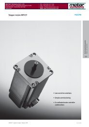
6 Stepping motor control amplifier board series SE...V1 and SE...E50 V1<br />
General notes<br />
Q Control of 2-phase-stepping motors<br />
Q Compatible with STÖGRA and Zebotronics standard amplifier boards series SE ...., SE ... E50, SE ... E50 D..<br />
Q Supply voltage - nominal voltage : 24 VDC to 240 VDC<br />
Q Phase current range 0 A/phase - 14,5 A/phase<br />
Q Boards SE ... E50 V1.. with integrated load angle control<br />
- together with Zebotronics E50 encoder (50 impulses per channel and revolution) at the motor<br />
( also available SE ... E200 V1.. for HP H200 encoder - 200 impulse per channel and revolution)<br />
Q Protection against shortcircuit, overtemperature and undervoltage<br />
Q Via solder bridges adjustable step angles: 200, 400 , 500 , 800 and 1000 steps per revolution<br />
Q EMC according to EN55011 class B and EN50082-2<br />
Versions - connector system and signal level of the inputs<br />
Q SE ... E50 V11 : Encoder connections via 9 pole D-Sub, all other signals and connections via 32 pole male connector<br />
(DIN 41612 type D) and SPS(PLC)-input signal level<br />
Q SE ... E50 V13 : Encoder connections via 9 pole D-Sub , all other signals and connections via 32 pole male connector<br />
(DIN 41612 type D) and TTL-input signal level<br />
Q SE ... V11 : All signals and connections via 32 pole male connector (DIN 41612 type D) and SPS(PLC)-input signal level<br />
Q SE ... V13 : All signals and connections via 32 pole male connector (DIN 41612 type D) and TTL-input signal level<br />
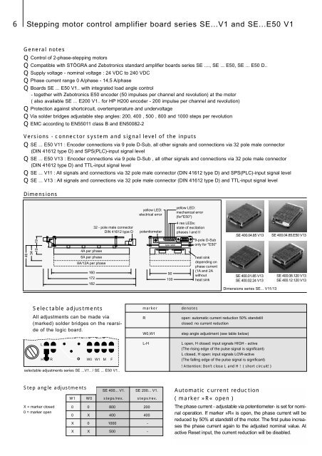
Dimensions<br />
yellow LED:<br />
electrical error<br />
yellow LED:<br />
mechanical error<br />
(for"E50")<br />
46<br />
34<br />
19 19<br />
4A per phase<br />
6A per phase<br />
8A/12A per phase<br />
160<br />
172<br />
182<br />
32 - pole male connector<br />
DIN 41612 type D<br />
potentiometer<br />
type label<br />
90<br />
100<br />
4 res LEDs:<br />
state of excitation<br />
phases I and II<br />
9-pole D-Sub<br />
only for "E50"<br />
heat sink<br />
depending on<br />
phase current<br />
(1A and 2A<br />
without<br />
heat sink<br />
SE 400.04.85 V13<br />
SE 400.01.85 V13<br />
SE 400.02.24 V13<br />
Dimensions series SE... V11/13<br />
SE 400.04.85.E50 V13<br />
SE 400.08.120 V13<br />
SE 400.12.120 V13<br />
Selectable adjustments<br />
All adjustments can be made via<br />
(marked) solder bridges on the rearside<br />
of the logic board.<br />
L<br />
H R W0 W1 M F<br />
selectable adjustments series SE ...V1.. / SE ... E50 V1..<br />
marker<br />
R<br />
W0,W1<br />
L-H<br />
denotes<br />
open: automatic current reduction 50% standstill<br />
closed: no current reduction<br />
step angle adjustment (see table below)<br />
L open, H closed: input signals HIGH - active<br />
(The rising edge of the pulse signal is significant)<br />
L closed, H open: input signals LOW-active<br />
(The falling edge of the pulse signal is significant)<br />
! Attention: Don’t close L and H ! ( short circuit! )<br />
Step angle adjustments<br />
X = marker closed<br />
0 = marker open<br />
SE 400... V1. SE 200... V1.<br />
W1 W0 steps/rev. steps/rev.<br />
0 0 800 200<br />
0 X 400 400<br />
X 0 1000 -<br />
X X 500 -<br />
Automatic current reduction<br />
( marker »R« open )<br />
The phase current - adjustable via potentiometer- is set for nominal<br />
operation. If marker »R« is open, the phase current will be<br />
reduced by 50% at standstill of the motor. The first pulse increases<br />
the phase current again to the adjusted nominal value. At<br />
active Reset input, the current reduction will be disabled.