STEPPING MOTOR CONTROLS - Motor Technology Ltd
STEPPING MOTOR CONTROLS - Motor Technology Ltd
STEPPING MOTOR CONTROLS - Motor Technology Ltd

Create successful ePaper yourself
Turn your PDF publications into a flip-book with our unique Google optimized e-Paper software.
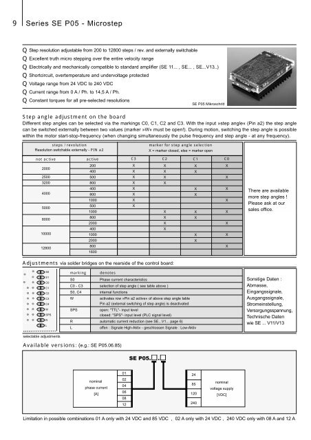
9 Series SE P05 - Microstep<br />
Q Step resolution adjustable from 200 to 12800 steps / rev. and externally switchable<br />
Q Excellent truth micro stepping over the entire velocity range<br />
Q Electrically and mechanically compatible to standard amplifier (SE 11... , SE... , SE...V13..)<br />
Q Shortcircuit, overtemperature and undervoltage protected<br />
Q Voltage range from 24 VDC to 240 VDC<br />
Q Current range from 0 A / Ph. to 14,5 A / Ph.<br />
Q Constant torques for all pre-selected resolutions<br />
SE P05 Mikroschritt<br />
Step angle adjustment on the board<br />
Different step angles can be selected via the markings C0, C1, C2 and C3. With the input »step angle« (Pin a2) the step angle<br />
can be switched externally between two values (marker »W« must be open!). During motion, switching the step angle is possible<br />
within the motor start-stop-frequency (when changing simultaneously the pulse frequency and step angle - at any frequency).<br />
steps / revolution<br />
Resolution switchable externally - PIN a2<br />
marker for step angle selection<br />
X = marker closed, else = marker open<br />
not active<br />
active<br />
C3<br />
C2<br />
C1<br />
C0<br />
2000<br />
2500<br />
200<br />
400<br />
500<br />
X<br />
X<br />
X<br />
X<br />
X<br />
X<br />
X<br />
X<br />
X<br />
X<br />
3200<br />
800<br />
X<br />
X<br />
4000<br />
5000<br />
8000<br />
400<br />
800<br />
1000<br />
500<br />
1000<br />
800<br />
2000<br />
X<br />
X<br />
X<br />
X<br />
X<br />
X<br />
X<br />
X<br />
X<br />
X<br />
X<br />
X<br />
X<br />
X<br />
X<br />
There are available<br />
more step angles !<br />
Please ask at our<br />
sales office.<br />
10000<br />
12800<br />
400<br />
1000<br />
2000<br />
800<br />
1600<br />
X<br />
X<br />
X<br />
X<br />
X<br />
Adjustments via solder bridges on the rearside of the control board:<br />
S0<br />
S1<br />
C0<br />
C1<br />
C2<br />
C3<br />
C4<br />
W<br />
SPS<br />
R<br />
L<br />
selectable adjustments<br />
marking denotes<br />
S0<br />
Phase current characteristics<br />
C0 - C3 selection of step angle ( see table above )<br />
S0, C4 internal functions<br />
W<br />
activates row »Pin a2 active« of above step angle table<br />
Pin a2 (external switching of step angle) is deactivated<br />
SPS<br />
open: "TTL"- input level<br />
closed: "SPS"- input level (PLC signal level)<br />
R automatic current reduction (see SE...V1... page 6)<br />
L<br />
offen : Signale High-Aktiv - geschlossen Signale : Low-Aktiv<br />
Sonstige Daten :<br />
Abmasse,<br />
Eingangssignale,<br />
Ausgangssignale,<br />
Stromeinstellung,<br />
Versorgungsspannung,<br />
Technische Daten<br />
wie SE ... V11/V13<br />
Available versions: (e.g.: SE P05.06.85)<br />
SE P05. .<br />
nominal<br />
phase current<br />
[A]<br />
01<br />
02<br />
04<br />
06<br />
08<br />
12<br />
24<br />
85<br />
120<br />
240<br />
nominal<br />
voltage supply<br />
[VDC]<br />
Limitation in possible combinations 01 A only with 24 VDC and 85 VDC , 02 A only with 24 VDC , 240 VDC only with 08 A and 12 A