STEPPING MOTOR CONTROLS - Motor Technology Ltd
STEPPING MOTOR CONTROLS - Motor Technology Ltd
STEPPING MOTOR CONTROLS - Motor Technology Ltd

Create successful ePaper yourself
Turn your PDF publications into a flip-book with our unique Google optimized e-Paper software.
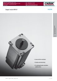
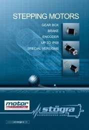
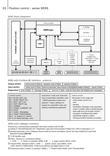
16 bit µ-controller<br />
E 2 PROM<br />
SERS-logic<br />
POWER AMPLIFIER<br />
encoderinput<br />
motorconnection<br />
limit switches<br />
stop switch<br />
home switch<br />
RAM<br />
interface<br />
I/O-port 2<br />
8 digitale<br />
inputs<br />
12 digital<br />
outputs<br />
(100 mA)<br />
parameter<br />
operstional<br />
programm<br />
I/O-port<br />
8 digitali nputs<br />
1 ADC (8 Bit, 0 - 5 VDC)<br />
4 digital outputs<br />
(500 mA)<br />
c a<br />
2<br />
4<br />
6<br />
8<br />
10<br />
12<br />
14<br />
16<br />
18<br />
20<br />
22<br />
24<br />
26<br />
28<br />
30<br />
32<br />
5<br />
4<br />
3<br />
2<br />
1<br />
5<br />
4<br />
3<br />
2<br />
1<br />
10<br />
11<br />
12<br />
13<br />
10<br />
11<br />
12<br />
13<br />
9<br />
8<br />
7<br />
6<br />
9<br />
8<br />
7<br />
6<br />
14<br />
15<br />
16<br />
17<br />
18<br />
19<br />
20<br />
21<br />
22<br />
23<br />
24<br />
25<br />
14<br />
15<br />
16<br />
17<br />
18<br />
19<br />
20<br />
21<br />
22<br />
23<br />
24<br />
25<br />
1<br />
2<br />
3<br />
4<br />
5<br />
6<br />
7<br />
8<br />
9<br />
1<br />
2<br />
3<br />
4<br />
5<br />
6<br />
7<br />
8<br />
9<br />
20 Position control - series SERS<br />
SERS block diagramm<br />
SERS with Profibus-DP interface - protocol:<br />
Output section control word (2 Byte) operation code (2 Byte) operand (4 Byte)<br />
Input section status word (2 Byte) result of parameter value request (4 Byte) actual position (4 Byte) inputs (2 Byte)<br />
Diagnostics error (2 Byte) warnings (2 Byte) error no. (1 Byte - code for more than 100 detailed error messages)<br />
control word<br />
Bit 0: SLOW_LEFT Jog<br />
Bit 1: SLOW_RIGHT Jog<br />
Bit 2: FAST_LEFT Jog<br />
Bit 3: FAST_RIGHT Jog<br />
Bit 4: HOMING<br />
Bit 5: PHASE_CURRENT_ON<br />
Bit 6: STOP<br />
Bit 7: START_PROGRAM<br />
Bit 8: START_POSITIONING<br />
Bit 9 - 12: Outputs O1 until O4<br />
Bit 13,14: Reset warnings / error<br />
operation code and operand<br />
input of parameters (operation code<br />
= SERS-parameter number and<br />
operand = value), starting of a<br />
request of a parameter value and<br />
writing of operational programms<br />
status word<br />
Explanation of the single bits:<br />
- motor phase current is on<br />
- error<br />
- warning<br />
- handshake (Operation code executed)<br />
- motor in position (after a positioning job)<br />
- load angle error (at encoder version)<br />
- excession of software limit switch<br />
- operational program is aktive<br />
- homing procedure finished succesfully<br />
SERS with CANopen interface:<br />
General (e.g. communication) parameters with index numbers until 0x1000 :<br />
according to "CiA Draft Standard 301" (Application Layer and Communication Profile) from "CAN in Automation e. V."<br />
Q standard parameter of the "CANopen Device Profile for Drives and Motion Control" ab Index 0x6000"CiA nach Draft<br />
Standard Proposal DSP-402"<br />
Q 11 Bit identifier used<br />
Q PDOs - Receive (3 x controlword (6040) ):<br />
1. 16 Bit / 2. modes_of_operation (6060), 8 Bit / 3. target_position (607a), 32 Bit<br />
Q Transmit PDO: statusword (6041), 16 Bit / position_actual_value (6064), 32 Bit<br />
LIMIT_SWITCH_DIGIN (2420), 16 Bit (Limit switches and digital inputs I1 to I8)<br />
Q Positioning modes (“modes_of_operation" (6060) ) : 1 "Profile Position Mode" and 6 "Homing Mode"