2013 Owner's Manual - Bear Archery
2013 Owner's Manual - Bear Archery
2013 Owner's Manual - Bear Archery

Create successful ePaper yourself
Turn your PDF publications into a flip-book with our unique Google optimized e-Paper software.
<strong>2013</strong><br />
Owner’s <strong>Manual</strong><br />
Members of the ATA<br />
817 Maxwell Avenue • Evansville, IN 47711<br />
800-694-9494 • fax 812-467-1245<br />
www.<strong>Bear</strong><strong>Archery</strong>Products.com
Contents<br />
Important Bow Information 3-5<br />
<strong>Archery</strong> Safety & Warnings 6-7<br />
Bow Diagrams 8-10<br />
Care & Maintenance 11-12<br />
Bow/Cam Adjustments 13-30<br />
Initial Bow Setup 32-36<br />
Arrow Selection Information 37<br />
Warranties 38-39<br />
Record important bow information here<br />
and keep for future reference.<br />
Model:__________________________<br />
Weight Range:___________________<br />
Draw Length:____________________<br />
String Length:___________________<br />
Cable Length:___________________<br />
Purchased From:_________________<br />
Date Purchased:__________________<br />
Serial Number:___________________<br />
2
Congratulations! Your new <strong>Bear</strong> <strong>Archery</strong><br />
compound bow is the finest available. It has been<br />
engineered for accuracy, long life, and built with<br />
quality and pride. No other bow delivers a higher<br />
performance to value ratio than a <strong>Bear</strong>. We know<br />
how much you are going to enjoy your new bow.<br />
For this reason, we ask you read the Care and<br />
Maintenance section carefully to learn how easy it<br />
is to maintain the quality, performance, and level<br />
of satisfaction you expect from a <strong>Bear</strong> <strong>Archery</strong><br />
product.<br />
ENJOY YOUR NEW BOW!<br />
! IMPORTANT LIMB !<br />
! INFORMATION !<br />
Your new <strong>Bear</strong> <strong>Archery</strong> bow uses<br />
the latest technology in limb design. This creates<br />
a limb capable of storing optimal amounts of<br />
energy unlike any other bow in the industry. For<br />
that reason, the use of limb mounted accessories<br />
such as vibration dampeners must be restricted.<br />
These particular accessories MUST NOT<br />
BE mounted more than 2 inches from the<br />
limb pockets. Mounting limb accessories<br />
more than 2 inches away from the pockets,<br />
particularly clamping type accessories, can<br />
potentially damage the limbs and void the<br />
warranty. See the illustration below.<br />
2” MAX<br />
Limb mounted<br />
accessories CAN BE<br />
MOUNTED IN<br />
THIS REGION OF<br />
THE LIMB ONLY.<br />
3
! IMPORTANT PRESS !<br />
! INFORMATION !<br />
Due to the innovative and advanced design of<br />
your <strong>Bear</strong> <strong>Archery</strong> bow limbs, it is of the utmost<br />
importance that your bow ONLY BE<br />
PRESSED IN PROPER BOW PRESSES.<br />
Traditional style presses that use rollers to apply<br />
pressure only to the mid section of the limbs<br />
CANNOT BE USED. Only presses that are<br />
capable of applying pressure to the last 2” of the<br />
limbs should be utilized, as illustrated below<br />
!NOTE! – Limb bolts MUST be backed out 4<br />
complete turns prior to pressing a bow equipped<br />
with flare quad limbs and 3 complete turns for<br />
bows equipped with max pre-load quad limbs.<br />
DO NOT USE THIS STYLE PRESS ARMS<br />
APPROVED BOW PRESSES:<br />
For the most up to date and accurate list, please<br />
visit your local <strong>Bear</strong> <strong>Archery</strong> dealer or<br />
www.<strong>Bear</strong><strong>Archery</strong>Products.com<br />
Failure to adhere to this list of<br />
presses can result in immediate failure of the<br />
limbs, possible injury and void the<br />
manufacturer’s warranty.<br />
4
! IMPORTANT PRESS !<br />
! INFORMATION !<br />
Certain bow models<br />
require the use of fixed<br />
stops to prevent the<br />
press forces from<br />
pushing the bow out of<br />
the bottom of the press<br />
Bow press MUST only<br />
be applied to the outer<br />
2” of limb tips.<br />
Press<br />
must<br />
ONLY<br />
apply<br />
pressure<br />
to the<br />
limbs in<br />
this<br />
area.<br />
Press<br />
should be<br />
capable of<br />
adjusting<br />
to the<br />
riser’s full<br />
length<br />
5
! SAFETY FIRST !<br />
Before using this equipment, read and follow<br />
these manufacturer’s instructions carefully. If you<br />
have any questions, contact the manufacturer or<br />
a qualified dealer.<br />
Dry-firing a bow severely reduces<br />
the life expectancy of the bow and may cause<br />
immediate damage to the bow resulting in injury<br />
to yourself or others. Never dry-fire your bow!<br />
Never pull back and release the bowstring<br />
without an arrow attached to the string. Your<br />
bow is designed to transfer energy to a properly<br />
weighted arrow.<br />
Shooting underweight arrows has<br />
the same effect as dry-firing a bow and may<br />
cause serious injury. Use the proper arrow for<br />
you and your bow. If you are unsure about your<br />
arrow choice, contact your local <strong>Bear</strong> <strong>Archery</strong><br />
dealer or an arrow manufacturer.<br />
Do not use wooden or fiberglass<br />
arrows. They are not designed for use with this<br />
compound bow and may cause serious injury.<br />
Use the proper arrow for you and your bow. If<br />
you are unsure about your arrow choice, contact<br />
your archery dealer or an arrow manufacturer.<br />
Inspect your arrows and nocks<br />
regularly. Immediately discard any dented, split,<br />
splintered or otherwise damaged arrows and<br />
replace cracked or broken nocks.<br />
Do not draw your bow beyond its<br />
maximum draw length as damage to the limbs,<br />
cables and strings could occur.<br />
The use of safety glasses is recommended with<br />
any archery product.<br />
6
! SAFETY FIRST !<br />
Targets and Hunting Safety<br />
‣ Be sure of your target. Bowhunters often<br />
wear camouflage and are difficult to<br />
identify.<br />
‣ Never aim at anything you don’t intend to<br />
shoot.<br />
‣ Never point or aim a drawn bow at<br />
another person.<br />
‣ Never draw or shoot when anyone is<br />
between you and your target.<br />
‣ Never shoot at a target or object unless<br />
you are sure that it can stop your arrows.<br />
‣ Make sure the area behind and around<br />
your target is clear.<br />
‣ Before shooting, be sure that no part of<br />
the bow will strike any tree branches or<br />
other obstacles.<br />
‣ Never shoot arrows straight up in the air<br />
or in any direction where you might<br />
destroy property or endanger life.<br />
Pre-shooting checklist<br />
Are these items in good condition<br />
Properly installed In working order<br />
___ Cables<br />
___ String<br />
___ String Serving<br />
___ Loop/Nock set<br />
___ Cable Slide<br />
___ Sight<br />
___ Arrow Rest<br />
___ Arrow Nocks<br />
___ Arrow Shafts<br />
___ Set Screws<br />
7
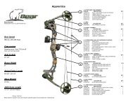
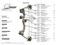
BOW DIAGRAMS<br />
Understanding your bow and its component<br />
parts will add to your archery enjoyment.<br />
Although bows differ in performance and<br />
features, these photos represent the components<br />
available in various combinations on most<br />
models. Being familiar with this information will<br />
help you with the instructions throughout this<br />
manual. Also, you can refer to these photos when<br />
ordering parts or making technical inquiries.<br />
Weighted<br />
Axle<br />
Dampeners<br />
Flare Quad<br />
Limbs<br />
Cable with<br />
Split Yoke<br />
Limb Bolt<br />
Assembly<br />
Arc String<br />
Suppressor<br />
Cable guard<br />
Continuous<br />
String<br />
Cable Slide<br />
Arrow Rest<br />
Mounting Holes<br />
8
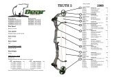
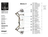
BOW DIAGRAMS<br />
Rocker<br />
Pivot<br />
Idler<br />
Wheel<br />
Limb<br />
Pocket<br />
Riser<br />
Sight Window and<br />
Mounting Holes<br />
Roller Cable<br />
Guard<br />
Rest Mounting Holes<br />
(Berger Hole)<br />
Grip<br />
Stabilizer<br />
Mounting<br />
Hole<br />
String<br />
Suppressor Rod<br />
String<br />
Suppressor<br />
Rubber<br />
Max Pre-Load<br />
Quad Limbs<br />
Cam<br />
Single Cam Bow<br />
9
BOW DIAGRAMS<br />
Limb<br />
Pocket<br />
Cap<br />
Limb<br />
Pocket<br />
Pivot<br />
Top<br />
Cam<br />
String<br />
Riser<br />
Buss<br />
Cable<br />
Sight Window and<br />
Mounting Holes<br />
Roller Cable<br />
Guard<br />
Rest Mounting Holes<br />
(Berger Hole)<br />
Control<br />
Cable<br />
Grip<br />
Stabilizer<br />
Mounting<br />
Hole<br />
String<br />
Suppressor Rod<br />
String<br />
Suppressor<br />
Rubber<br />
Max Pre-Load<br />
Quad Limbs<br />
Bottom Cam<br />
Hybrid Cam Bow<br />
10
CARE AND<br />
MAINTENANCE<br />
With proper care and a minimum amount of<br />
routine maintenance, your bow will be kept in<br />
top condition. However, it is still important to<br />
carefully inspect your bow on a regular basis.<br />
Cleaning<br />
Your bow should be kept clean of dust, mud and<br />
grime. Use a damp soft cotton cloth to remove<br />
dirt and moisture. Do not use solvents such as<br />
acetone or mineral spirits as they may ruin the<br />
finish.<br />
Storage and Transportation<br />
Avoid exposing your bow to temperatures over<br />
150 degrees. Excessive heat may damage your<br />
bow. Do not leave your bow unprotected in your<br />
vehicle on a hot sunny day or store in a hot attic<br />
or other hot enclosed area. Clean your bow<br />
thoroughly after each use. Never put your bow<br />
away wet or store it in a damp place. Lightly oil<br />
all steel parts (axles, mounting screws) to prevent<br />
rust. You can relax the limbs if storing for more<br />
than a year. Follow the instructions under Peak<br />
Draw Weight Adjustment in the bow adjustment<br />
section.<br />
Bow Presses<br />
Use only “double-pull” type APPROVED bow<br />
presses. A “double-pull” bow press draws your<br />
bow down at two points on the riser. Older style<br />
“single-pull” bow presses that contact the bow<br />
only in the grip area can result in bent or broken<br />
risers.<br />
To reduce unnecessary stress on the riser, back<br />
off the limb bolts 2-3 turns before placing in a<br />
press. See page 4 and/or<br />
www.<strong>Bear</strong><strong>Archery</strong>Products.com for additional<br />
bow press information.<br />
11
CARE AND<br />
MAINTENANCE<br />
Lubrication<br />
Your <strong>Bear</strong> <strong>Archery</strong> compound bow requires very<br />
little lubrication. Wipe the cable guard<br />
periodically with a dry cloth to keep the cable<br />
slide running smoothly and free of dust. Cam and<br />
idler wheel bearings do not require lubrication. If<br />
other lubrication is necessary, use white lithium<br />
grease or Teflon lubricants. Avoid excessive<br />
lubrication of any item, as this can attract dirt.<br />
On hunting bows, avoid lubricants with obvious<br />
odors.<br />
String and Synthetic Cable Maintenance<br />
Regularly apply a high quality bowstring wax to<br />
your string and synthetic cable system. Regular<br />
waxing protects your cables and strings from<br />
abrasion, wear and separation. Smear the wax<br />
into position. Then, rub it gently with your<br />
fingers or a soft piece of leather to work the wax<br />
into the strands. Replace frayed or worn<br />
bowstrings and cables immediately.<br />
•<strong>Bear</strong> <strong>Archery</strong> strongly recommends replacing<br />
the bowstring and cable annually. Please visit<br />
your local <strong>Bear</strong> <strong>Archery</strong> dealer for assistance.<br />
12
BOW ADJUSTMENTS<br />
Peak Draw Weight Adjustment<br />
<strong>Bear</strong> <strong>Archery</strong> bows have an approximate 10<br />
pound peak weight adjustment range. If your<br />
bow is equipped with limb bolt lock downs,<br />
make sure these screws (small single button head<br />
screw attached to riser through “tang”<br />
protruding from underneath the limb pocket) are<br />
loosened before making any weight adjustments.<br />
Using a 7/32” hex wrench for bows with a 3/8-<br />
16 limb bolt, and a 3/16” hex wrench for bows<br />
with a 5/16-18 limb bolt, turn the limb bolts<br />
clockwise to increase peak weight and counterclockwise<br />
to reduce peak weight. Bow weight will<br />
increase or decrease approximately two to four<br />
pounds per turn. IMPORTANT Both limb<br />
bolts must be adjusted equally. Likewise, do not<br />
turn one limb bolt more than two turns ahead of<br />
the other when making adjustments. Finally, limb<br />
bolts must never be backed out more than the<br />
specified number of full turns on bows that are<br />
equipped with max pre-load quad limbs. Also, do<br />
not back out the limb bolts more than the<br />
specified number of full turns for bows equipped<br />
with flare quad limbs unless otherwise noted.<br />
Bows with limb bolt lockdowns: After all tuning<br />
adjustments have been made; engage the limb<br />
bolt lock down screws. Screws should be snug<br />
against the limb pocket “tang”.<br />
13
BOW ADJUSTMENTS<br />
Counter-<br />
Clockwise<br />
Decreases<br />
Peak Weight<br />
Clockwise<br />
Increases<br />
Peak Weight<br />
Limb Bolt<br />
Assembly<br />
Limb Bolt<br />
Lockdown<br />
Tang &<br />
Screw<br />
Limb Bolt Adjustment<br />
Bow Max Turns<br />
Motive 4<br />
Empire 4<br />
Anarchy 4<br />
Method 4<br />
Domain 4<br />
Legion 3<br />
Encounter 3<br />
Outbreak 8<br />
Siren 3<br />
Homewrecker 3<br />
Apprentice 2 6<br />
14
CAM ADJUSTMENTS<br />
Adjusting Draw Length – H13 Synchronized<br />
Hybrid Cam System<br />
Bow model:<br />
• Motive 6<br />
• Motive 7<br />
• Method<br />
Module # Motive 6 Motive 7 Method<br />
5.5 25 1/2 26 1/2 26 1/2<br />
6 26 27 27<br />
6.5 26 1/2 27 1/2 27 1/2<br />
7 27 28 28<br />
7.5 27 1/2 28 1/2 28 1/2<br />
8 28 29 29<br />
8.5 28 1/2 29 1/2 29 1/2<br />
9 29 30 30<br />
9.5 29 1/2 30 1/2 30 1/2<br />
10 30 31 31<br />
The H13 Synchronized Hybrid cam has a rotating<br />
module for draw length adjustment. All draw length<br />
adjustments can be made without the use of a bow<br />
press. Draw length changes are made by simply<br />
rotating the modules to the desired position and<br />
moving the draw stop. To change draw length, remove<br />
the socket head cap screws from the top and bottom<br />
modules, rotate the modules to the desired<br />
positions(line up the indicator mark on the cam with<br />
the correct draw length indicator mark on the module),<br />
making sure to align the top and bottom to the same<br />
setting, and reapply the screws. Next, remove the<br />
draw stop on both the top and bottom cam and<br />
remount it in the corresponding stop locations to the<br />
draw length you selected. Such module draw length<br />
adjustments will not affect peak draw weight or timing.<br />
Modules are right and left hand specific and top<br />
and bottom specific. USE ONLY RH MODULES<br />
ON RIGHT HAND CAMS AND LH MODULES ON<br />
LH CAMS, AND ONLY USE TOP MODULES ON<br />
TOP CAMS AND BOTTOM MODULES ON<br />
BOTTOM CAMS!<br />
15
CAM ADJUSTMENTS<br />
H13 Synchronized Hybrid Cam System<br />
Axle<br />
<strong>Bear</strong>ing<br />
String<br />
Post<br />
Top Stop<br />
Control<br />
Cable<br />
Post<br />
Cam<br />
Indicator<br />
Mark<br />
Top<br />
Module<br />
Module<br />
Indicator<br />
Marks<br />
Module<br />
Mounting<br />
Screws<br />
TOP CAM (front view)<br />
Stop<br />
Mounting<br />
Screw<br />
TOP CAM (back view)<br />
16
CAM ADJUSTMENTS<br />
H13 Synchronized Hybrid Cam System<br />
Buss<br />
Cable<br />
Post<br />
Control<br />
Cable<br />
Post<br />
Bottom<br />
Stop<br />
Control<br />
Cable<br />
Track<br />
Cam<br />
Indicator<br />
Mark<br />
Module<br />
Indicator<br />
Marks<br />
Bottom<br />
Module<br />
BOTTOM CAM (front view)<br />
Control<br />
Cable<br />
Post<br />
Screw<br />
Module<br />
Mounting<br />
Screws<br />
Stop<br />
Mounting<br />
Screw<br />
BOTTOM CAM (back view)<br />
17
CAM ADJUSTMENTS<br />
H13 Synchronized Hybrid Cam System<br />
In order for the H13 Synchronized<br />
Hybrid Cam system to operate at<br />
maximum efficiency the timing<br />
needs to be set correctly. This<br />
means that the top and bottom<br />
cams roll over and hit their<br />
respective draw stops at the same<br />
time. The H13 Cam timing is set<br />
during assembly at the factory, but<br />
once the bow is broken in, or if<br />
you change strings/cables it is<br />
possible that the cam timing will<br />
need to be checked.<br />
If the H13 Cam System is out of<br />
time and the top stop hits before<br />
the bottom stop, put more twists<br />
into the control cable until both<br />
stops hit at the same time. If the<br />
H13 Cam System is out of time,<br />
and the bottom stop hits before<br />
the top stop, take twists out of the<br />
control cable until both stops hit at<br />
the same time. The high quality<br />
string materials used in your <strong>Bear</strong><br />
Bow will exhibit very little stretch<br />
and should maintain proper timing<br />
for extended periods under normal<br />
use.<br />
18
CAM ADJUSTMENTS<br />
Adjusting Draw Length – Perimeter<br />
Weighted Modular Single Cam ( ½” size<br />
module draw length adjustment)<br />
Bow model:<br />
• Anarchy<br />
Draw length Module #<br />
31.5” 9.5<br />
31” 9<br />
30.5” 8.5<br />
30” 8<br />
29.5” 7.5<br />
29” 7<br />
28.5” 6.5<br />
28” 6<br />
27.5” 5.5<br />
27” 5<br />
26.5” 4.5<br />
26” 4<br />
25.5” 3.5<br />
25” 3<br />
The perimeter weighted single cam has a modular<br />
draw length adjustment. All draw length<br />
adjustments can be made without the use of a<br />
bow press. Draw length changes are made by<br />
simply changing modules and moving the draw<br />
stop. Accessory modules are available from your<br />
local <strong>Bear</strong> <strong>Archery</strong> dealer in half-inch draw<br />
length increments. Each module is numbered,<br />
with #9.5 being the longest draw length and #3<br />
being the shortest. To change modules remove<br />
the socket head cap screws from the present<br />
module, remove that module and replace with a<br />
new module. Such module draw length<br />
adjustments will not affect peak draw weight.<br />
Modules are right and left hand specific. USE<br />
ONLY RH MODULES ON RIGHT HAND<br />
CAMS AND LH MODULES ON LH CAMS!<br />
19
Setting the TWO SIDED DRAW<br />
STOP<br />
When a module is changed, the draw stop must<br />
also be moved to the corresponding setting<br />
marked on the cam. The Anarchy has a two<br />
sided draw stop system. This system consists of<br />
a draw stop that utilizes two mounting bosses to<br />
achieve different draw stop settings. Each draw<br />
stop is marked with a 1 on one side and a ½ on<br />
the other side. These marks are used to match<br />
the stop with the desired module. If a whole<br />
number module is to be used, the draw stop<br />
must have the 1 facing out when mounted, if a<br />
half number module is to be used, the draw stop<br />
must have the ½ facing out when mounted.<br />
There is only one mounting hole in the cam for<br />
each whole and half number module set. For<br />
example, when setting a bow up with either a<br />
number 6 or a number 6 ½ module, the stop will<br />
mount in the #6 hole for both settings, but on<br />
the 6 module, the stop will read “1” facing out,<br />
and on the 6 ½ module, the stop will read “1/2”<br />
facing out. The stop will only mount in one<br />
orientation for each setting. DO NOT force the<br />
stop into the mounting hole; it will slip into the<br />
hole when the correct orientation is achieved.<br />
Example Shown:<br />
Refer to the images on the next page for<br />
additional reference.<br />
20
TWO SIDED DRAW STOP<br />
EXAMPLES<br />
#6 Module<br />
Draw Stop<br />
Position for<br />
# 6 Module<br />
#6.5 Module<br />
Draw Stop<br />
Position for<br />
#6.5 Module<br />
21
CAM ADJUSTMENTS<br />
Module number<br />
engraved in<br />
module<br />
Module<br />
Draw Stop<br />
Back View<br />
Draw<br />
Stop<br />
Screw<br />
Perimeter<br />
Weight<br />
Module<br />
Mounting<br />
Screws<br />
#9 and #9.5<br />
Draw Stop<br />
Position<br />
#8 and #8.5<br />
Draw Stop<br />
Position<br />
Front View<br />
22<br />
5, 5.5 Draw<br />
Position<br />
6, 6.5 Draw<br />
Position<br />
7, 7.5 Draw<br />
Position<br />
3, 3.5 Draw<br />
Position<br />
4, 4.5 Draw<br />
Position
CAM ADJUSTMENTS<br />
Adjusting Draw Length – Rotating Module<br />
System<br />
Bow models:<br />
• Empire<br />
• Domain<br />
• Legion<br />
• Encounter<br />
• Siren<br />
Module #<br />
Setting<br />
Empire DL Domain DL Legion DL Encounter DL Siren DL<br />
4 24 - - - -<br />
4.5 24.5 - - - -<br />
5 25 26 26 27 22<br />
5.5 25.5 26.5 26.5 27.5 22.5<br />
6 26 27 27 28 23<br />
6.5 26.5 27.5 27.5 28.5 23.5<br />
7 27 28 28 29 24<br />
7.5 27.5 28.5 28.5 29.5 24.5<br />
8 28 29 29 30 25<br />
8.5 28.5 29.5 29.5 30.5 25.5<br />
9 29 30 30 31 26<br />
9.5 29.5 30.5 30.5 31.5 26.5<br />
10 30 31 31 32 27<br />
10.5 30.5 - - - -<br />
11 31 - - - -<br />
The rotating module cam system allows the bow<br />
to be adjusted to all of its draw length positions<br />
without the use of separate individual modules<br />
and does not require a bow press for draw length<br />
adjustments at 1/2” increments. Draw length<br />
changes are made by first removing the socket<br />
head cap screws that secure the rotating module<br />
unit. Next, rotate the module until the desired<br />
module draw length module tick mark is lined up<br />
with the cam tick mark, and reinstall the screws<br />
in the corresponding holes. Such draw length<br />
adjustments will not affect peak draw weight.<br />
When the rotating module unit is repositioned to<br />
adjust draw length, the draw stop must also be<br />
moved to the corresponding setting marked on<br />
the cam.<br />
23
Module<br />
Indicator<br />
Marks<br />
CAM ADJUSTMENTS<br />
<strong>2013</strong> SINGLE CAM<br />
Rotating<br />
Module<br />
Screws<br />
String<br />
Post<br />
Cam<br />
Indicator<br />
Mark<br />
Cam<br />
String<br />
Post<br />
Front View<br />
Rotating<br />
Module<br />
Perimeter<br />
weight<br />
Cable<br />
Post<br />
Draw Stop<br />
mounting<br />
holes<br />
Draw stop<br />
Front View<br />
24
CAM ADJUSTMENTS<br />
Cable<br />
Post<br />
String<br />
Post<br />
Draw stop<br />
Rotating<br />
Module<br />
Draw length<br />
increments<br />
engraved in<br />
cam<br />
Cam<br />
Module Tick<br />
Mark<br />
Back View<br />
Rotating<br />
Module<br />
Screws<br />
Perimeter<br />
weight<br />
String<br />
Post<br />
Draw stop<br />
screws<br />
Draw stop<br />
increments<br />
MUST MATCH<br />
draw length<br />
setting<br />
Front View<br />
25
CAM ADJUSTMENTS<br />
Thread<br />
Locked<br />
Screws<br />
Siren Rotating Module Cam Back View<br />
Bolt on<br />
third track<br />
Cam<br />
The Siren rotating module cam is equipped<br />
with a bolt on third track system.<br />
DO NOT remove the third track for any<br />
reason. The screws holding this track on<br />
have been set with a thread binding agent<br />
and should never be removed. The third<br />
track is not changed during any adjustment<br />
of this cam.<br />
26
CAM ADJUSTMENTS<br />
Adjusting Draw Length – Perimeter<br />
Weighted Modular Single Cam<br />
Bow model:<br />
• Home Wrecker<br />
The perimeter weighted single cam has a<br />
modular draw length adjustment. Most<br />
draw length adjustments can be made<br />
without the use of a bow press. Draw<br />
length changes are made by simply<br />
changing modules and moving the draw<br />
stop. Accessory modules are available<br />
from your local <strong>Bear</strong> <strong>Archery</strong> dealer in<br />
one-inch draw length increments. Each<br />
module is numbered, with #10 being the<br />
longest draw length and #4 being the<br />
shortest. To change modules remove the<br />
socket head cap screws from the present<br />
module, remove that module and replace<br />
with a new module. Such module draw<br />
length adjustments will not affect peak<br />
draw weight. Modules are right and<br />
left hand specific. USE ONLY RH<br />
MODULES ON RIGHT HAND CAMS<br />
AND LH MODULES ON LH CAMS!<br />
When a module is changed, the draw<br />
stop must also be moved to the<br />
corresponding setting marked on the<br />
cam. Draw stop must be positioned so<br />
that the side marked “OUT” faces out.<br />
27
CAM ADJUSTMENTS<br />
Additionally, fine draw length<br />
adjustments of ½ inch can be made by<br />
removing the bowstring from the<br />
standard “dot” string post and<br />
reattaching it to either the “+” or “-“<br />
string posts on the cam. Moving the<br />
string to the “+” post will increase draw<br />
length by ½” and moving the string to<br />
the “-“ post will decrease draw length by<br />
½”. To make such adjustments, it is first<br />
necessary to remove tension from the<br />
harness system of the bow by<br />
compressing the bow in a bow press. A<br />
fixed or portable bow press must be<br />
used! Under NO circumstances can<br />
this relaxing of the harness system be<br />
accomplished by simply backing out<br />
limb bolts. Refer to the images on the<br />
next page for additional reference.<br />
Home Wrecker Draw Lengths<br />
Modular Single Cam Draw Length Chart<br />
String on "Dot" Post String on "+" Post String on "-" Post<br />
Module Number<br />
Draw Length Draw Length Draw Length<br />
4 22 22.5 21.5<br />
5 23 23.5 22.5<br />
6 24 24.5 23.5<br />
7 25 25.5 24.5<br />
8 26 26.5 25.5<br />
9 27 27.5 26.5<br />
10 28 28.5 27.5<br />
28
CAM ADJUSTMENTS<br />
Module<br />
number<br />
“+”<br />
Post<br />
Module<br />
Standard<br />
“dot”<br />
Post<br />
Draw Stop<br />
MUST<br />
FACE<br />
OUT<br />
Back View<br />
Standard<br />
“dot” Post<br />
“-“<br />
Post<br />
Module<br />
Mounting<br />
Screws<br />
Perimeter<br />
Weight<br />
Draw<br />
Stop<br />
Screws<br />
Front View<br />
Draw stop<br />
increments<br />
must match<br />
module<br />
number<br />
29
CAM ADJUSTMENTS<br />
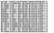
Adjusting Draw Length – Rotating Modular<br />
Cam System with MultiDraw<br />
Bow model:<br />
• Apprentice 2<br />
• Outbreak<br />
The adjustable multidraw cam equipped bow can<br />
be configured to provide a draw length from 14”<br />
to 27” in 1” intervals. No bow press is required<br />
to adjust the multidraw cam system. To adjust<br />
the draw length, first remove the socket head cap<br />
screw located in the rotating module. Next rotate<br />
the module to the desired draw length and<br />
reinstall the screw in the corresponding hole. It<br />
may be necessary to pull the cable away from the<br />
module to provide clearance for the module to<br />
rotate, see the picture below. Next perform the<br />
same operation on the opposite cam. Be sure that<br />
both the top and bottom cams are set to the<br />
same draw length position. The adjustable cam<br />
operates on a sliding poundage scale where an<br />
increase in draw length also provides an increase<br />
in peak draw weight. This allows the bow to<br />
grow with the archer. The chart below shows the<br />
peak draw weight at each draw length for the 40<br />
and 50 pound peak bows.<br />
Module<br />
Mounting<br />
Screw<br />
Right or<br />
left hand<br />
designation<br />
Cam<br />
Back View<br />
Draw Length<br />
printed on<br />
module<br />
Front View<br />
30
Rotating<br />
Module<br />
OUTBREAK<br />
Draw Weight vs. Draw Length Chart<br />
Module<br />
Mounting<br />
Screws<br />
Cam<br />
Cable Post<br />
String Post<br />
Draw Length<br />
60 lb<br />
Apprentice 2<br />
Draw Length [in] vs Draw Weight [lbs]<br />
Limb Bolt Bottomed<br />
50 lb<br />
Apprentice 2<br />
Outbreak<br />
60 lb<br />
Apprentice 2<br />
(6 turns)<br />
Limb Bolt Fully Backed Out<br />
50 lb<br />
Apprentice 2<br />
(6 turns)<br />
Outbreak<br />
(8 turns)<br />
15 39.5-43.5 30-34 - 21-25 14.5-18.5 -<br />
16 39.5-43.5 30-34 28-32 21-25 14.5-18.5 16-20<br />
17 39.5-43.5 30-34 28.5-32.5 21-25 14.5-18.5 16-20<br />
18 40-44 31.5-35.5 32.5-36.5 23-27 16-20 19-23<br />
19 43.5-47.5 34-38 37-41 24.5-28.5 17.5-21.5 21.5-25.5<br />
20 45.5-49.5 36.5-40.5 41-45 26-30 20-24 24.5-28.5<br />
21 48-52 39.5-43.5 45-49 28-32 21.5-25.5 27-31<br />
22 50-54 40.5-44.5 49.5-53.5 29.5-33.5 23-27 30-34<br />
23 51.5-55.5 42.5-46.5 53-57 31-35 24.5-28.5 32.5-36.5<br />
24 53-57 44-48 56.5-60.5 32.5-36.5 26-30 35-39<br />
25 55-59 46-50 59.5-63.5 34.5-38.5 28-32 37.5-41.5<br />
26 56.5-60.5 47.5-51.5 62.5-66.5 37-41 30.5-34.5 39.5-43.5<br />
27 60-64 50-54 64.5-68.5 40.5-44.5 34-38 41.5-45.5<br />
28 - 66.5-70.5 - 43.5-47.5<br />
29 - 68.5-72.5 - 45.5-49.5<br />
30 - 70-74 - 48-52<br />
31
INITIAL BOW SETUP<br />
Before you can safely and effectively shoot your<br />
bow, a number of specific initial bow setup steps<br />
must be taken. These steps can be performed on<br />
your own, if your level of expertise is adequate.<br />
Or, your local <strong>Bear</strong> <strong>Archery</strong> dealer can help you.<br />
Arrow Rest Installation & Setup<br />
Arrow rests should be installed according to the<br />
manufacturer’s specifications. The first<br />
adjustment you need to perform is setting the<br />
vertical height of your arrow rest. When properly<br />
adjusted, your arrow rest should align the<br />
centerline of the arrow with the center of the two<br />
holes used to mount the rest to the riser. To<br />
check this, place an arrow in the rest and nocked<br />
on the string. Visually confirm the center of the<br />
arrow passes directly through the center of the<br />
arrow rest mounting holes when viewed from the<br />
side. If not, adjust your rest up or down to<br />
correct.<br />
Next, the rest should be adjusted for proper<br />
“Centershot”. With an arrow in the rest and<br />
nocked on the string, firmly hold another arrow<br />
against the inside of the riser near the arrow rest<br />
mounting holes as illustrated. Look down the<br />
arrows and verify that the arrows are parallel to<br />
each other. In other words, the spacing between<br />
the two arrows should be the same along the<br />
entire length of the arrows. If not, adjust your<br />
rest side to side to correct. This is only your<br />
“initial” centershot and additional fine tuning<br />
may be required depending on your shooting<br />
style and equipment. Please refer to the images<br />
on the next page for further reference.<br />
32
INITIAL BOW SETUP<br />
Place<br />
arrow<br />
firmly<br />
against<br />
inside of<br />
riser as<br />
shown.<br />
Arrow<br />
rest<br />
should<br />
support<br />
the arrow<br />
in such a<br />
way that<br />
the<br />
arrow’s<br />
centerline<br />
passes<br />
directly<br />
through<br />
the<br />
center of<br />
the two<br />
arrow<br />
rest<br />
mounting<br />
holes.<br />
Arrows<br />
should be<br />
parallel<br />
along their<br />
entire<br />
length.<br />
33
INITIAL BOW SETUP<br />
Nocking Point and Nock Adjustment<br />
Now that the initial centershot setting is<br />
complete, you need to verify your arrow nocking<br />
point. Install the nocking point or string loop on<br />
the bowstring so that when an arrow is nocked it<br />
creates a 90 degree angle to the string. Another<br />
option is to use a process similar to the one used<br />
to determine centershot. With an arrow in the<br />
rest and nocked on the string, firmly hold<br />
another arrow against the shelf of the riser as<br />
illustrated. Look down the arrows and verify that<br />
the arrows are parallel. In other words, the<br />
spacing between the two arrows should be the<br />
same along the entire length of the arrows. If<br />
not, adjust your nocking point up or down to<br />
correct.<br />
At this time, adjust arrow fletch position to<br />
correspond with the arrow rest you are using.<br />
Such adjustments are done by simply rotating or<br />
replacing the arrow’s nock. Carefully position the<br />
nock to provide proper fletch clearance through<br />
the arrow rest. Your local <strong>Bear</strong> <strong>Archery</strong> dealer<br />
can show you how to do this or can provide the<br />
service for you. Please refer to the images on the<br />
next page for further reference.<br />
Install All Accessories<br />
After your arrow rest and nocking point are<br />
installed correctly you will need to install all other<br />
accessories such as sights, quivers, silencers, peep<br />
sights, stabilizers, etc. Before mounting ANY<br />
accessories to the limbs, Refer to page 3 for<br />
important limb information.<br />
34
INITIAL BOW SETUP<br />
90°<br />
Max<br />
Place arrow firmly<br />
against shelf of<br />
riser as shown.<br />
Arrows should<br />
be parallel<br />
along their<br />
entire length<br />
35
INITIAL BOW SETUP<br />
Sight Adjustment<br />
When first sighting in your new bow or bow<br />
sight, the key thing to remember is “Chase the<br />
arrows”. In other words if your arrows are hitting<br />
the target to the right of the bull’s-eye, move<br />
your sight to the right. If the arrows hit high on<br />
the target, raise your sight.<br />
Arrow<br />
Group<br />
In the picture above, the arrows are hitting the target<br />
high and to the right of the bull’s-eye. To correct this,<br />
adjust your sight up and to the right. Remember,<br />
“Chase the arrows.”<br />
36
ARROW SELECTION<br />
Arrow selection depends on the peak draw<br />
weight, let-off and draw length settings of your<br />
bow. Refer to arrow manufacturer’s arrow<br />
selection tables using this information. The<br />
International Bowhunters Organization (IBO)<br />
allows a minimum of five grains arrow weight<br />
per pound of peak weight. Arrow weight is the<br />
total combined weight of your arrow nock insert,<br />
and point or broadhead. To determine the<br />
lightest arrow you can safely shoot, use the<br />
following format:<br />
Peak Draw<br />
Weight (Lb)<br />
X =<br />
Multiply by<br />
5 Grains<br />
per Pound<br />
Minimum Safe<br />
Arrow Weight<br />
(Grains)<br />
Shooting arrows below these<br />
minimum weight requirements will void the<br />
warranty. Using arrows below five grains per<br />
pound of peak weight can approach dry-fire<br />
conditions and can severely reduce the life of<br />
your bow, and may cause serious injury. Contact<br />
your local <strong>Bear</strong> <strong>Archery</strong> pro shop or arrow<br />
manufacturers for arrow selection<br />
recommendations.<br />
The weight of the arrow you select can be<br />
determined as follows:<br />
1. From an arrow chart, find the weight of<br />
your arrow shaft based on the size and<br />
length.<br />
2. Add the weight of your broadhead or<br />
point.<br />
3. Add 35 grains to cover the nock, insert,<br />
and fletching. For example.<br />
Arrow<br />
400-30”<br />
240 Gr<br />
Point<br />
Mag 125<br />
(+125 Gr)<br />
Other<br />
(+35 Gr)<br />
+ + =<br />
Total<br />
Weight<br />
(=400 Gr)<br />
NOTE: It is always best to use a grain scale<br />
when available.<br />
37
<strong>Bear</strong> <strong>Archery</strong> Warranty Statement<br />
All <strong>Bear</strong> <strong>Archery</strong> compound bows are backed<br />
with a Limited Lifetime Warranty to the original<br />
owner. This warranty applies to limbs, risers, and<br />
cams. This warranty consists of the following<br />
programs:<br />
•Limbs: 100% covered at no charge for the first 5<br />
years, 50% of replacement cost after.<br />
•Risers: Lifetime Warranty.<br />
•Cams: Lifetime Warranty.<br />
Original Owner:<br />
Warranty applies only to the original owner and<br />
is not transferable. Proof of purchase may be<br />
required.<br />
Items Not Covered:<br />
Cables, strings, bearings, paint and/or film<br />
dipped finishes resulting from normal wear and<br />
tear are not included in this warranty.<br />
Damage Not Covered:<br />
Damage caused by abuse, mishandling, dry firing,<br />
alteration or modification made to original<br />
products are not covered under this warranty.<br />
The use of any bow press other than those<br />
approved by <strong>Bear</strong> <strong>Archery</strong> will void this<br />
warranty. Additionally, shooting of arrows less<br />
than 5 grains per pound of peak draw weight will<br />
void this warranty. <strong>Bear</strong> <strong>Archery</strong> reserves the<br />
right to make parts substitutions on warranty<br />
coverage at <strong>Bear</strong> <strong>Archery</strong>’s sole discretion, for<br />
any reason.<br />
Bow Warranty Registration:<br />
For this warranty to be in effect, the on-line<br />
warranty registration process must be completed<br />
at <strong>Bear</strong><strong>Archery</strong>Products.com and submitted<br />
within 30 days of purchase.<br />
Traditional Bows: 1 year Limited Warranty to<br />
the original owner.<br />
Youth Bows: 90 Day Limited Warranty to the<br />
original owner.<br />
38
<strong>Bear</strong> <strong>Archery</strong> Warranty Statement<br />
In the event a bow requires warranty service,<br />
please contact the <strong>Bear</strong> <strong>Archery</strong> Customer<br />
Department at 800-694-9494 for a return<br />
authorization (RA) number and return shipping<br />
instructions. For full warranty details, please log<br />
on to <strong>Bear</strong><strong>Archery</strong>Products.com for further<br />
information.<br />
Key Contact data:<br />
Dealer 800 Number: 800-694-9494<br />
Dealer Fax Number: 812-467-1245<br />
Web: www.<strong>Bear</strong><strong>Archery</strong>Products.com<br />
©2012 <strong>Bear</strong> <strong>Archery</strong><br />
2L-7213-13<br />
39