
Create successful ePaper yourself
Turn your PDF publications into a flip-book with our unique Google optimized e-Paper software.
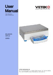
INDICATORS<br />
<strong>DGT</strong><br />
SERIES<br />
User Manual<br />
<strong>DGT</strong> _06_10.04_EN_U
<strong>DGT</strong> / <strong>DGT</strong>60 / <strong>DGT</strong>Q / <strong>DGT</strong>P / <strong>DGT</strong>PK / <strong>DGT</strong>20<br />
INDEX<br />
1. INTRODUCTION.................................................................................................................................................................3<br />
2. MAIN TECHNICAL SPECIFICATIONS...............................................................................................................................4<br />
3. SYMBOLS...........................................................................................................................................................................5<br />
4. INSTALLATION ..................................................................................................................................................................6<br />
4.1 <strong>DGT</strong>4 CASE AND DIMENSIONS ..................................................................................................................................6<br />
4.2 <strong>DGT</strong>60 CASE AND DIMENSIONS ................................................................................................................................7<br />
4.3 <strong>DGT</strong>Q CASE AND DIMENSIONS..................................................................................................................................8<br />
4.4 <strong>DGT</strong>P CASE AND DIMENSIONS..................................................................................................................................9<br />
4.5 <strong>DGT</strong>PK CASE AND DIMENSIONS..............................................................................................................................10<br />
4.6 <strong>DGT</strong>20 CASE AND DIMENSIONS ..............................................................................................................................11<br />
5. POWER SUPPLY & START UP .......................................................................................................................................12<br />
6. FRONT PANEL KEYS AND INDICATORS ......................................................................................................................13<br />
6.1 <strong>DGT</strong>4 ...........................................................................................................................................................................13<br />
6.2 <strong>DGT</strong>60 .........................................................................................................................................................................13<br />
6.3 <strong>DGT</strong>Q ..........................................................................................................................................................................14<br />
6.4 <strong>DGT</strong>P...........................................................................................................................................................................14<br />
6.5 <strong>DGT</strong>PK ........................................................................................................................................................................15<br />
6.6 <strong>DGT</strong>20 .........................................................................................................................................................................15<br />
6.7 FUNCTION OF THE INDICATORS .............................................................................................................................16<br />
6.8 FUNCTIONS OF THE KEYS: ......................................................................................................................................17<br />
7. BASIC FUNCTIONS .........................................................................................................................................................18<br />
7.1 SCALE ZERO ..............................................................................................................................................................18<br />
7.2 TARE OPERATIONS...................................................................................................................................................18<br />
7.3 LIMITATION OF THE TARE FUNCTIONS ..................................................................................................................19<br />
7.4 AUTO POWER OFF FUNCTION.................................................................................................................................19<br />
7.5 MULTI RANGE FUNCTIONING (for legal for trade approved instruments).................................................................20<br />
7.6 DATE/TIME ADJUSTMENT (OPTIONAL) ...................................................................................................................20<br />
7.7 "SCREEN SAVER" FUNCTION (OPTIONAL) .............................................................................................................20<br />
7.8 PRINTING....................................................................................................................................................................21<br />
7.9 REENABLING THE PRINTOUTS AND THE INDICATOR FUNCTIONS.....................................................................22<br />
7.10 DISPLAY OF METRIC DATA (inFO) .........................................................................................................................22<br />
7.11 SELECTION OF THE CHANNEL TO BE DISPLAYED..............................................................................................22<br />
7.12 REMOTE CONTROL (OPTIONAL, JUST WITH <strong>DGT</strong>60 MODEL) ............................................................................23<br />
8. SELECTABLE OPERATING MODES ..............................................................................................................................23<br />
8.1 UNIT OF MEASURE CONVERSION (Std) .................................................................................................................24<br />
8.2 NET/GROSS SWITCH (ntGS) .....................................................................................................................................25<br />
8.3 INPUT/OUTPUT (in / out) ............................................................................................................................................25<br />
8.4 MULTISCALE REPEATER (MAStr).............................................................................................................................26<br />
8.5 ALIBI MEMORY (ALibi) (OPTIONAL) ..........................................................................................................................27<br />
8.6 SINGLE SCALE REPEATER (rEPE) ...........................................................................................................................30<br />
8.7 DISPLAY WITH SENSITIVITY X 10 (VISS) (TO BE USED IN TESTING DURING THE CALIBRATION) ...................31<br />
8.8 HOLD: FREEZING THE WEIGHT ON THE DISPLAY (hLd)........................................................................................31<br />
8.9 PEAK WEIGHT PEAKS DETECTION (PEAk) ...........................................................................................................31<br />
8.10 HORIZONTAL TOTALIZER (Sum of lots) (tot o).......................................................................................................32<br />
8.11 VERTICAL TOTALIZER (Sum by recipe) (tot S)........................................................................................................33<br />
8.12 PIECE COUNTING (Coun) ........................................................................................................................................34<br />
8.13 SIMULTANEOUS TRANSMITTER OF THE CHANNEL VALUE (tYPE: trAnSM) ......................................................36<br />
9. SET-POINT FUNCTIONS .................................................................................................................................................37<br />
10. INSTRUMENT MESSAGES WHILE IN USE ..................................................................................................................42<br />
11. PRINT EXAMPLES.........................................................................................................................................................43<br />
DECLARATION OF CONFORMITY .....................................................................................................................................44<br />
WARRANTY .........................................................................................................................................................................44<br />
2
<strong>DGT</strong> / <strong>DGT</strong>60 / <strong>DGT</strong>Q / <strong>DGT</strong>P / <strong>DGT</strong>PK / <strong>DGT</strong>20<br />
1. INTRODUCTION<br />
The purpose of this <strong>manual</strong> is to help the <strong>user</strong> get to know the weight indicator’s various functioning modes, the keys’<br />
functions and the display indications. It is possible that one may incur into the phrase "TECH.MAN.REF.": this means that<br />
an advanced function is being described (therefore, for the technical personnel) and which is further explained in the<br />
corresponding technical <strong>manual</strong>.<br />
We advise to carefully follow the instructions for programming the weight indicator; by taking actions not<br />
indicated this <strong>manual</strong>, one could cause the scale to not work properly.<br />
In addition to having all the characteristics of a high precision scale, the indicator has the unit of measure conversion<br />
function, switching in the display, net/gross weight, set point on gross weight/net weight/pieces, in/out weigh, multiscale<br />
repeater, alibi memory, hold function, peak detector, weighs totaliser and piece counter.<br />
These features make it suitable for industrial use as well as for legal for trade use in relation with third parties and in<br />
commerce, satisfying the frequently needed ability to transmit and print the data through its two bidirectional serial ports.<br />
This <strong>manual</strong> has been made as carefully and exactly as possible; in any case, your suggestions are always<br />
welcome.<br />
WARNING<br />
Any attempt to repair or alter the unit can expose the <strong>user</strong> to the danger of electric shock and it will void our warranty. This<br />
instrument is covered under warranty provided that IT HAS NOT BEEN OPENED BY THE USER for any reason. If any<br />
problem with the unit or system has been experienced please notify the manufacturer or the dealer from which the<br />
instrument was acquired.<br />
!!WARNING!!<br />
For ATEX version please read carefully the ATEX attachment in this <strong>manual</strong><br />
Do not pour liquids on the indicator!<br />
Do not use solvents to clean the indicator!<br />
Do not expose instrument to either direct sun light or any heat sources!<br />
Always mount the indicator and platform in a vibration free setting!<br />
All indicator connections must be made respecting the norms applicable to the zone and<br />
environment in which it will be installed.<br />
Read carefully & apply what described in the POWER SUPPLY & START-UP section!<br />
Do not install in an environment with any risk of explosion!(except ATEX3GD version)<br />
RECYCLING INSTRUCTION<br />
The crossed-out wheeled bin on the product means that at the product end of life, it must be taken to<br />
separate collection or to the reseller when a new equivalent type of equipment is purchased. The<br />
adequate differentiated refuse collection in having the product recycled, helps to avoid possible<br />
negative effects on the environment and health and supports the recycling of the materials of which the<br />
equipment is made. The unlawful disposal of the product by the <strong>user</strong> will entail fines foreseen by the<br />
current regulations.<br />
3
2. MAIN TECHNICAL SPECIFICATIONS<br />
<strong>DGT</strong> / <strong>DGT</strong>60 / <strong>DGT</strong>Q / <strong>DGT</strong>P / <strong>DGT</strong>PK / <strong>DGT</strong>20<br />
POWER SUPPLY 12÷24 Vdc +/-10%<br />
MAXIMUM ABSORPTION<br />
<strong>DGT</strong>4/<strong>DGT</strong>60/<strong>DGT</strong>Q/<strong>DGT</strong>P/<strong>DGT</strong>PK/<strong>DGT</strong>20: 100 mA at 12 V; 70 mA at 24V<br />
(without load cells) <strong>DGT</strong>4AN/<strong>DGT</strong>QAN/<strong>DGT</strong>PAN/<strong>DGT</strong>20AN: 185 mA at 12 V; 90 mA at 24 V<br />
<strong>DGT</strong>4PB/<strong>DGT</strong>QPB/<strong>DGT</strong>20PB:<br />
410 mA at 12 V; 220 mA at 24V<br />
<strong>DGT</strong>PPB:<br />
70 mA at 12 V; 35mA at 24V<br />
OPERATING TEMPERATURE<br />
From -10 to +40 °C.<br />
DISPLAY DIVISIONS<br />
10000e, 3 x 3000e for legal weighing, expandable up to 800.000 for internal<br />
use (with minimum signal coming from a 1,6mV/V cell).<br />
CONVERSION SPEED<br />
200 conv./sec with automatic selection.<br />
MINIMUM VOLTAGE PER DIVISION 0.3 µV (approved instrument); 0.03 µV (non approved instrument).<br />
COUNTING RESOLUTIONS<br />
1'500’000 points (with input signal equal to 3mV/V).<br />
DISPLAY<br />
<strong>DGT</strong>4/<strong>DGT</strong>60/<strong>DGT</strong>Q: 6 digits, h 13 mm.<br />
<strong>DGT</strong>P/<strong>DGT</strong>PK/<strong>DGT</strong>20 : 6 digits, h 20 mm<br />
<strong>DGT</strong>60: 6 digits, h 60 mm<br />
INDICATIONS<br />
<strong>DGT</strong>4/<strong>DGT</strong>60/<strong>DGT</strong>Q/<strong>DGT</strong>P/<strong>DGT</strong>20: 6 status indicator LEDs.<br />
<strong>DGT</strong>PK: 12 status indicator LEDs<br />
KEYBOARD<br />
<strong>DGT</strong>4/<strong>DGT</strong>60/<strong>DGT</strong>Q/<strong>DGT</strong>P/<strong>DGT</strong>20: Waterproof 5-key keyboard<br />
<strong>DGT</strong>PK: Waterproof 20-key keyboard<br />
TARE FUNCTION<br />
Subtractive possible on the entire capacity.<br />
AUTO SWITCH-OFF FUNCTION Programmable from 1 to 255 minutes, or disinserted.<br />
LOAD CELL POWER SUPPLY<br />
5Vdc ± 5%, 120mA (up to 8 cells of 350 Ohm each).<br />
LOAD CELL CONNECTION 6 wires (CELL1) with Remote Sense, 4 wires (CELLS 2, 3, 4).<br />
CASE<br />
<strong>DGT</strong>4 model: Plastic console suitable for mounting on DIN bar or on the wall.<br />
<strong>DGT</strong>60 model: STAINLESS STEEL case with fixed bracket (standard fitting) or<br />
"STFR" adjustable bracket (OPTIONAL) for mounting or on the wall.<br />
<strong>DGT</strong>Q model: Case for panel mounting in self-extinguishing NORYL UL 94-V0,<br />
according to DIN 43700 norms, colour black.<br />
<strong>DGT</strong>P model: Plastic case for panel mounting.<br />
<strong>DGT</strong>PK/<strong>DGT</strong>20 model: PAINTED STEEL case with adjustable bracket<br />
(standard fitting) or fixed bracket (OPTIONAL) for mounting on the wall.<br />
SERIAL OUTPUTS<br />
1 RS485 bidirectional port configurable for connection to a PC/PLC or WEIGHT<br />
REPEATER (<strong>DGT</strong>4, <strong>DGT</strong>4AN, <strong>DGT</strong>60, <strong>DGT</strong>Q, <strong>DGT</strong>QAN, <strong>DGT</strong>P, <strong>DGT</strong>PK,<br />
<strong>DGT</strong>PAN , <strong>DGT</strong>20 and <strong>DGT</strong>20AN versions).<br />
1 RS232 bidirectional port configurable for connection to a printer.<br />
1 PROFIBUS port (<strong>DGT</strong>4PB, <strong>DGT</strong>QPB, <strong>DGT</strong>20PB and <strong>DGT</strong>PPB versions).<br />
1 external PROFIBUS port (optional, only for <strong>DGT</strong>PK version)<br />
OUTPUTS / INPUTS<br />
2 photomosfet outputs (expandable to 6 through option for the <strong>DGT</strong>Q model,<br />
for <strong>DGT</strong>P model 6 series outputs) NO or NC, configurable programmable<br />
weight thresholds:<br />
- <strong>DGT</strong>4, <strong>DGT</strong>60, <strong>DGT</strong>20 and <strong>DGT</strong>P models: 48 Vac 0,15 A max (or 60 Vdc<br />
0,15 A max)<br />
- <strong>DGT</strong>Q model: 48 Vac 0,12 A max (or 60 Vdc 0,12 A max)<br />
2 configurable inputs (for <strong>DGT</strong>P/<strong>DGT</strong>PK models, 4 inputs) (optoisolator<br />
Photocouplers): 12÷24 Vdc, 5 mA min - 20 mA max<br />
Input reading time and output refreshing time: 1msec.<br />
Optoisolated analogue output at 16 bit (at choice 4÷20 mA, 0÷5 Vdc or 0÷10<br />
Vdc (<strong>DGT</strong>4AN, <strong>DGT</strong>QAN, <strong>DGT</strong>20AN and <strong>DGT</strong>P versions); the maximum<br />
resistance applicable on the output current is 350 Ohm and the minimum<br />
resistance applicable on the output voltage is 10 kohm.<br />
4
<strong>DGT</strong> / <strong>DGT</strong>60 / <strong>DGT</strong>Q / <strong>DGT</strong>P / <strong>DGT</strong>PK / <strong>DGT</strong>20<br />
3. SYMBOLS<br />
To call the attention of the <strong>user</strong>, the following symbols are used both in the <strong>manual</strong> and on the instrument itself:<br />
Warning! This operation must be performed only by qualified personal<br />
CE CONFORMITY<br />
IDENTIFIES THE CLASS OF PRECISION<br />
"TECH.MAN.REF."<br />
means that an advanced function is being described (therefore for the technical personnel) which<br />
will be further explained in the corresponding technical <strong>manual</strong>.<br />
5
<strong>DGT</strong> / <strong>DGT</strong>60 / <strong>DGT</strong>Q / <strong>DGT</strong>P / <strong>DGT</strong>PK / <strong>DGT</strong>20<br />
4. INSTALLATION<br />
4.1 <strong>DGT</strong>4 CASE AND DIMENSIONS<br />
The indicator has a plastic case, whose external dimensions<br />
are shown in FIGURE 4.1.<br />
Figure 4.1 – Measurements and dimensions in mm<br />
1 (+) 12V / 24 Vdc power supply input<br />
2 GND power supply input<br />
3 Connections for serial lines / inputs / outputs<br />
4 Connections for load cells<br />
The instrument may be installed on the wall or on the panel on the DIN bar.<br />
NOTE: When the identification plate is supplied separately (therefore not attached to the front panel) it is advisable<br />
to attach it in the appropriate space on the indicator, so that it can be identified.<br />
6
<strong>DGT</strong> / <strong>DGT</strong>60 / <strong>DGT</strong>Q / <strong>DGT</strong>P / <strong>DGT</strong>PK / <strong>DGT</strong>20<br />
4.2 <strong>DGT</strong>60 CASE AND DIMENSIONS<br />
The indicator has a STAINLESS STEEL case, whose external<br />
dimensions are shown in FIGURE 4.2 and 4.3.<br />
MODEL WITH FIXED BRACKET (STANDARD FITTING)<br />
Figure 4.2 – Measurements and dimensions in mm<br />
2<br />
1<br />
MODEL WITH "STFR" ADJUSTABLE BRACKET (OPTIONAL)<br />
Figure 4.3 – Measurements and dimensions in mm<br />
1 Power supply input.<br />
2 Available for load cells / serial lines / inputs / outputs<br />
2<br />
1<br />
The instrument may be installed on the wall.<br />
NOTE: When the identification plate is supplied separately (therefore not attached to the front panel) it is advisable<br />
to attach it in the appropriate space on the indicator, so that it can be identified.<br />
7
<strong>DGT</strong> / <strong>DGT</strong>60 / <strong>DGT</strong>Q / <strong>DGT</strong>P / <strong>DGT</strong>PK / <strong>DGT</strong>20<br />
4.3 <strong>DGT</strong>Q CASE AND DIMENSIONS<br />
The indicator has a plastic case, whose external<br />
dimensions are shown in FIGURE 4.4.<br />
Figure 4.4 – Measurements and dimensions in mm<br />
1) Power supply cable input<br />
2) GND power supply input<br />
3) Connections for serial lines / inputs / analogic output<br />
4) Connection for load cell<br />
5) Connections for outputs<br />
The instrument may be installed on the panel.<br />
NOTE: When the identification plate is supplied separately (therefore not attached to the front panel) it is advisable<br />
to attach it in the appropriate space on the indicator, so that it can be identified.<br />
8
<strong>DGT</strong> / <strong>DGT</strong>60 / <strong>DGT</strong>Q / <strong>DGT</strong>P / <strong>DGT</strong>PK / <strong>DGT</strong>20<br />
4.4 <strong>DGT</strong>P CASE AND DIMENSIONS<br />
The indicator has a plastic case, whose external<br />
dimensions are shown in FIGURE 4.5.<br />
Figure 4.5 – Measurements and dimensions in mm<br />
1) Power supply cable input.<br />
2) GND power supply input.<br />
3) Connections for serial lines / analogic output.<br />
4) Connection for load cell.<br />
5) Connections for inputs / outputs.<br />
The instrument may be installed on the panel.<br />
NOTE: When the identification plate is supplied separately (therefore not attached to the front panel) it is advisable<br />
to attach it in the appropriate space on the indicator, so that it can be identified.<br />
9
<strong>DGT</strong> / <strong>DGT</strong>60 / <strong>DGT</strong>Q / <strong>DGT</strong>P / <strong>DGT</strong>PK / <strong>DGT</strong>20<br />
4.5 <strong>DGT</strong>PK CASE AND DIMENSIONS<br />
The indicator has a PAINTED STEEL case, whose external<br />
dimensions are shown in FIGURE 4.6.<br />
2<br />
1 3<br />
Figure 4.6 – Measurements and dimensions in mm<br />
1) Power supply cable input.<br />
2) Available for load cells / serial lines / inputs / outputs<br />
3) RJ45 connector<br />
The instrument may be installed on the wall.<br />
NOTE: When the identification plate is supplied separately (therefore not attached to the front panel) it is advisable<br />
to attach it in the appropriate space on the indicator, so that it can be identified.<br />
10
<strong>DGT</strong> / <strong>DGT</strong>60 / <strong>DGT</strong>Q / <strong>DGT</strong>P / <strong>DGT</strong>PK / <strong>DGT</strong>20<br />
4.6 <strong>DGT</strong>20 CASE AND DIMENSIONS<br />
The indicator has a PAINTED STEEL case, whose external<br />
dimensions are shown in FIGURE 4.7.<br />
4<br />
1 3<br />
Figure 4.7 – Measurements and dimensions in mm<br />
1) Power supply cable input.<br />
2) Available for load cells / serial lines / inputs / outputs<br />
3) RJ45 connector<br />
4) Profibus<br />
2<br />
The instrument may be installed on the wall.<br />
NOTE: When the identification plate is supplied separately (therefore not attached to the front panel) it is advisable<br />
to attach it in the appropriate space on the indicator, so that it can be identified.<br />
11
<strong>DGT</strong> / <strong>DGT</strong>60 / <strong>DGT</strong>Q / <strong>DGT</strong>P / <strong>DGT</strong>PK / <strong>DGT</strong>20<br />
5. POWER SUPPLY & START UP<br />
INSTRUMENT POWER SUPPLY:<br />
<strong>DGT</strong>4 , <strong>DGT</strong>Q, <strong>DGT</strong>P, <strong>DGT</strong>PK and <strong>DGT</strong>20 models<br />
The instrument must be powered with stabilized voltage at 12 Vdc or 24 Vdc supplied from an AC/DC external charger (not<br />
supplied) which should be connected to the 220 Vac mains voltage.<br />
TO POWER the instrument, connect the two power supply cables (+ and -) in the appropriate terminal board (section 4<br />
"INSTALLATION", Fig. 4.1, 4.4, 4.5) on the side or on the rear of the instrument.<br />
<strong>DGT</strong>60 model<br />
The instrument is powered with stabilized voltage at 12 Vdc or 24 Vdc supplied from an AC/DC internal charger (supplied)<br />
which should be connected to the 220 Vac mains voltage.<br />
<strong>DGT</strong>603GD model<br />
See ATEX ATTACHMENT in this <strong>manual</strong>.<br />
Safety norms must be respected for the connection to the mains voltage including the use of a line which has to be free<br />
from noise generated by other electronic equipment.<br />
Do not connect other equipment to the same socket as the one that the adapter is in.<br />
Do not step on or crush the power supply cable<br />
TO TURN ON THE INSTRUMENT, keep the C – ON/OFF key pressed until the indicator turns on, and then release the<br />
key.<br />
The display executes a start-up procedure, and will indicate:<br />
XX.YY is the installed software version.<br />
The indicator has an "auto zero at start-up" function: in other words it means that if at start-up a weight within +/- 10% of the<br />
capacity is detected, it will be zeroed; if the weight is not within this tolerance, with a non approved instrument the display<br />
shows the present weight after a few instants, while with an approved instrument "ZEro" is shown continuously on the<br />
display, until the weight is made to re-enter within this tolerance; the auto zero function at start-up may be disabled in the<br />
set-up environment (only with non approved instrument); see SEtuP >> ConFiG >> Param. >> Auto-0 (TECH.MAN.REF.)<br />
By pressing the ZERO key for an instant while the version is shown in the LED display, the indicator will show the following<br />
in this order:<br />
XX.YY<br />
in which XX is the software release and YY is the sub release.<br />
CLoCK<br />
if there is the optional board.<br />
09.01 in which 09 indicates the type of the instrument, 01 indicates the metrological software version.<br />
XX.YY.ZZ<br />
is the installed software version.<br />
dGt, dGt60 , dGtq<br />
, dgtk or dGtP is the name of the installed software.<br />
n.Ch X number of the configured channels (if equal to 2, 3,or 4)<br />
XXX.XXX capacity and division of channel 1<br />
After this, the instrument "hi rES" is displayed (in case of non approved instrument), or "LEGAL"(in case of approved<br />
instrument), together with the gravitational acceleration value of the area of use.<br />
Then, the instrument executes a countdown (self-check).<br />
NOTE: the display of the other information is described in section 7.10 DISPLAY OF METRIC DATA (inFO).<br />
TO PUT THE INSTRUMENT IN STANDBY: keep the C – ON/OFF key pressed until the message "- OFF –" appears on the<br />
display and then release the key; just the point at the extreme left of the display remains on.<br />
TO TURN OFF THE INSTRUMENT: take away the power supply.<br />
12
6. FRONT PANEL KEYS AND INDICATORS<br />
The front panel of the indicator is designed for quick but simple weighing applications for the <strong>user</strong>.<br />
<strong>DGT</strong> / <strong>DGT</strong>60 / <strong>DGT</strong>Q / <strong>DGT</strong>P / <strong>DGT</strong>PK / <strong>DGT</strong>20<br />
6.1 <strong>DGT</strong>4<br />
The front panel of the <strong>DGT</strong>4 consists of a display with 6 digits, 13 mm high, 6 LED function indicators and a 5-key<br />
keyboard.<br />
1 2 3 4 5 6<br />
<strong>DGT</strong> Weight<br />
Transmitter<br />
Figure 6.1 – Keys and indicators of the <strong>DGT</strong>4 front panel<br />
6.2 <strong>DGT</strong>60<br />
The front panel of the <strong>DGT</strong>60 consists of a display with 6 digits, 60 mm high, 6 LED function indicators and a 5-key<br />
keyboard.<br />
1<br />
2<br />
3<br />
5<br />
6<br />
4<br />
7<br />
Figure 6.2 – Keys and indicators of the <strong>DGT</strong>60 front panel<br />
13
<strong>DGT</strong> / <strong>DGT</strong>60 / <strong>DGT</strong>Q / <strong>DGT</strong>P / <strong>DGT</strong>PK / <strong>DGT</strong>20<br />
6.3 <strong>DGT</strong>Q<br />
The front panel of the indicator is designed for quick but simple weighing applications for the <strong>user</strong>. It consists of a display<br />
with 6 digits, 13 mm high, 6 LED function indicators and a 5-key keyboard.<br />
1<br />
2 3 4 5 6<br />
NET<br />
F<br />
W1<br />
S P1<br />
W2<br />
SP2<br />
Figure 6.3 – Keys and indicators of the <strong>DGT</strong>Q front panel<br />
6.4 <strong>DGT</strong>P<br />
The front panel of the <strong>DGT</strong>P consists of a display with 6 digits, 20 mm high, 6 LED function indicators and a 5-key<br />
keyboard.<br />
1 2 3 4 5 6<br />
Figure 6.4 – Keys and indicators of the <strong>DGT</strong>P front panel<br />
14
<strong>DGT</strong> / <strong>DGT</strong>60 / <strong>DGT</strong>Q / <strong>DGT</strong>P / <strong>DGT</strong>PK / <strong>DGT</strong>20<br />
6.5 <strong>DGT</strong>PK<br />
The front panel of the <strong>DGT</strong>PK consists of a display with 6 digits, 20 mm high, 12 LED function indicators and a 20-key<br />
keyboard.<br />
1 2 3 4 8 9<br />
6.6 <strong>DGT</strong>20<br />
Figure 6.5 – Keys and indicators of the <strong>DGT</strong>PK front panel<br />
The front panel of the <strong>DGT</strong>20 consists of a display with 6 digits, 20 mm high, 6 LED function indicators and a 5-key<br />
keyboard.<br />
1 2 3 4 5 6<br />
Figure 6.6 – Keys and indicators of the <strong>DGT</strong>20 front panel<br />
15
<strong>DGT</strong> / <strong>DGT</strong>60 / <strong>DGT</strong>Q / <strong>DGT</strong>P / <strong>DGT</strong>PK / <strong>DGT</strong>20<br />
6.7 FUNCTION OF THE INDICATORS<br />
NUMBER<br />
FUNCTION<br />
(1) Indicates that the weight detected by the weighing system is near zero, specifically within - ¼ ÷ ¼<br />
of the division.<br />
(2) Indication of UNSTABLE WEIGHT<br />
(3) Indicates that the displayed value is a NET WEIGHT.<br />
(4)<br />
It turns on when:<br />
- the SPECIFIC FUNCTION of the instrument is ACTIVE, which is set in the FMODE >> FunCt<br />
parameter<br />
- a key is pressed.<br />
It turns off:<br />
- when the SPECIFIC FUNCTION of the instrument IS DISABLED.<br />
- with an active function, a key is pressed.<br />
When blinking it means that the instrument function is active for 5 seconds<br />
(5)<br />
If instrument in dual range and approved: one’s within the 1 st weighing range (w1).<br />
In the other cases: It shows the activation of the 1 st OUTPUT (Sp1).<br />
(6)<br />
If instrument in dual range and approved: one’s within the 2 nd weighing range (w2)<br />
In the other cases: It shows the activation of the 2 nd OUTPUT (Sp2).<br />
(7) Sensor for the reception of the infrared signal (standard fitting, only for the <strong>DGT</strong>60 model).<br />
(8)<br />
If instrument in dual range and approved: one’s within the 1 st weighing range (w1)<br />
If instrument in dual range and approved: one’s within the 2 nd weighing range (w2)<br />
(9) The relays nr. 1,2,3,4,5,6 has been enabled.<br />
16
<strong>DGT</strong> / <strong>DGT</strong>60 / <strong>DGT</strong>Q / <strong>DGT</strong>P / <strong>DGT</strong>PK / <strong>DGT</strong>20<br />
6.8 FUNCTIONS OF THE KEYS:<br />
<strong>DGT</strong>4, <strong>DGT</strong>60,<br />
<strong>DGT</strong>P, <strong>DGT</strong>20 KEY<br />
ZERO ▼<br />
TARE ▲<br />
MODE ►<br />
PRINT<br />
<strong>DGT</strong> / <strong>DGT</strong>60 / <strong>DGT</strong>Q / <strong>DGT</strong>P / <strong>DGT</strong>PK / <strong>DGT</strong>20<br />
7. BASIC FUNCTIONS<br />
7.1 SCALE ZERO<br />
By pressing the ZERO key it is possible to zero a gross weight value which is within +/- 2% of the capacity; after the<br />
zeroing, the display shows 0 weight and the relative pilot lights turn on.<br />
7.2 TARE OPERATIONS<br />
SEMIAUTOMATIC TARE<br />
By pressing the TARE key any weight value present on the display is tared: the display shows "tArE" for an instant and<br />
then 0 (net weight); the relative keys turn on.<br />
NOTE: The semiautomatic tare will be acquired only if the weight is AT LEAST A DIVISION, STABLE (instability ~ led<br />
off) and VALID (in other words, the OVERLOAD condition should not be created).<br />
MANUAL TARE FROM KEYBOARD<br />
Press TARE for a few seconds: the display shows "– tM –" and then "000000". Enter the desired value using the<br />
following keys:<br />
ZERO decreases the blinking digit.<br />
TARE increases the blinking digit.<br />
MODE selects the digit to be modified (blinking); the scrolling of the digits takes place from left to right.<br />
C– ON/OFF if pressed for an instant it quickly zeros the present value; if pressed at length it allows to return to weighing<br />
without saving the changes made.<br />
Confirm with the PRINT key; the value will be subtracted from the weight present on the plate and the relative pilot lights will<br />
turn on.<br />
If the entered value is not a multiple of the scale’s minimum division, it will be rounded off.<br />
CANCELLING A TARE<br />
One can <strong>manual</strong>ly cancel the tare value in different ways:<br />
- unload the scale and press the TARE or ZERO key.<br />
- carry out the tares in deduction, partially unloading the scale and pressing TARE to zero the display.<br />
- press C – ON/OFF without unloading the scale.<br />
- enter a <strong>manual</strong> tare equal to 0.<br />
NOTE: it is possible to automatically cancel the tare value by doing the following:<br />
SELECTION OF LOCKED/UNLOCKED/DISABLED TARE<br />
Normally, when a tare value is entered (automatic, <strong>manual</strong>, or from storage) by unloading the scale plate, the display<br />
shows the tare value with a negative sign (LOCKED TARE). For one’s convenience it is also possible to choose that the<br />
tare value cancels itself automatically each time that the scale is unloaded (UNLOCKED TARE); or disable the tare<br />
functions.<br />
With the UNLOCKED tare:<br />
- In case of SEMIAUTOMATIC TARE the net weight, before unloading the scale, may also be 0.<br />
- In case of MANUAL TARE the net weight before unloading the scale must be greater than 2 divisions and<br />
stable.<br />
18
<strong>DGT</strong> / <strong>DGT</strong>60 / <strong>DGT</strong>Q / <strong>DGT</strong>P / <strong>DGT</strong>PK / <strong>DGT</strong>20<br />
To set the type of tare:<br />
- Turn on the indicator, press the TARE key while the firmware version is displayed (the display shows the "tYPE"<br />
menu).<br />
- Select "F.ModE" (by pressing once the ZERO key) and press PRINT to enter in the menu.<br />
- Press ZERO many times (to scroll ahead through the parameters) or TARE (to scroll backwards) until one finds the<br />
"tArE t" parameter.<br />
- Press PRINT to enter the parameter.<br />
- With the ZERO or TARE keys select the possible options: "LoCK" (locked tare), "unLoCK" (unlocked tare), diSAb<br />
(disabled tare).<br />
- Confirm with PRINT.<br />
- Press the C – ON/OFF key many times until the display shows the message "SAVE".<br />
- Press PRINT to confirm the changes made or another key for not saving.<br />
The indicator stores the last selection made, also after it is turned off.<br />
7.3 LIMITATION OF THE TARE FUNCTIONS<br />
With approved instrument, it is possible to limit the tare functions, selecting: SEtuP >> d.SALE >> yES (TECH.MAN.REF.)<br />
the tare operations will have the following specifications:<br />
SCALE CAPACITY<br />
FUNCTIONING<br />
< 100kg All the tare functions are disabled<br />
- The SEMIAUTOMATIC TARE value can not be modified with a<br />
≥ 100kg<br />
<strong>manual</strong> tare.<br />
- The <strong>manual</strong> tare can be entered or modified only with an<br />
UNLOADED scale.<br />
With approved instrument , the step d.SALE are not modifiable<br />
7.4 AUTO POWER OFF FUNCTION<br />
It is possible to automatically turn off the indicator (from 1 to 255 minutes), or disable it; the auto power off takes place<br />
when, with unloaded scale, the weight has not been moved or a key has not been pressed for the time set: the display<br />
shows the "- oFF – " blinking message, after this the indicator turns off.<br />
For the setting, follow the procedures below:<br />
- Turn on the scale, press the TARE key while the firmware version is displayed (the display shows the "tYPE" menu).<br />
- Select "F.ModE" (by pressing once the ZERO key) and press PRINT to enter in the menu.<br />
- Press ZERO many times (to scroll ahead through the parameters) or TARE (to scroll backwards) until one finds the<br />
"AutoFF" parameter.<br />
- Press PRINT to enter the parameter.<br />
- With the ZERO or TARE keys select the possible options: "diSAb" (auto switch-off disabled), "EnAb" (auto switch-off<br />
enabled).<br />
- Confirm with PRINT; if "EnAb" has been selected, one will be asked to enter the number of minutes after which the<br />
indicator should turn off: enter a number between 1 and 255 (using the MODE key to select the digit to be modified and<br />
ZERO/TARE to decrease/increase it) and confirm with PRINT.<br />
- Press many times the C – ON/OFF key until the display shows "SAVE".<br />
- Press PRINT to confirm the changes made or another key for not saving.<br />
19
7.5 MULTI RANGE FUNCTIONING (for legal for trade approved instruments)<br />
<strong>DGT</strong> / <strong>DGT</strong>60 / <strong>DGT</strong>Q / <strong>DGT</strong>P / <strong>DGT</strong>PK / <strong>DGT</strong>20<br />
The multirange functioning allows to subdivide the scale capacity in two or three ranges, each which is up to 3000<br />
divisions, improving in this way the first range division in the dual range.<br />
For example, with a 10 kg cell platform it is possible to approve the weighing system with:<br />
- A single range: 6 kg capacity and 2 g division (3000 div.).<br />
- Dual range: 6 / 3 kg capacity and 2/1 g division (3000 + 3000 div.).<br />
NOTES:<br />
- For the approval of the weighing system in dual range the cell must have better technical features in comparison to the<br />
cell used for the approval in a single range.<br />
The multirange functioning is shown by the turning on of the relative LED which identifies the range in which one is<br />
operating; by passing to the second range, the second range division is enabled. At this point the first range division is<br />
restored only by passing by the gross zero of the scale.<br />
- The selection of the range number with multirange functioning is made during the indicator’s calibration<br />
(TECH.MAN.REF.).<br />
7.6 DATE/TIME ADJUSTMENT (OPTIONAL)<br />
The indicator can be fitted with the date/time option; in this case, the "CLoCK" message is shown when the instrument is<br />
turned on. To set the date/time follow the procedure below:<br />
- Turn on the scale, press the TARE key while the firmware version is displayed (the display shows the "tYPE" menu).<br />
- Select "F.ModE" (by pressing once the ZERO key) and press PRINT to enter in the menu.<br />
- Press ZERO many times (to scroll forwards through the parameters) or TARE (to scroll backwards) to find the "CLoCK"<br />
parameter.<br />
- Confirm with PRINT: in this order one will be asked to enter the day, month, year, hour, and minutes. The entry of each<br />
parameter must be confirmed with PRINT.<br />
- Press the C – ON/OFF key many times until the message "SAVE" appears on the display.<br />
- Press PRINT to confirm the changes made or another key to not save.<br />
NOTE:<br />
- the "CLoCK" parameter is not displayed if there is no date/time option.<br />
- the clock/calendar function is standard fitted on the <strong>DGT</strong>P/<strong>DGT</strong>PK version.<br />
7.7 "SCREEN SAVER" FUNCTION (OPTIONAL)<br />
If the indicator is fitted with the date/time function, it is possible to enable the "Screen Saver": after a programmable time<br />
(from 1 to 255 minutes) with the scale unloaded, the time is shown on the display, in the "HH-MM.SS" format. As soon as<br />
a weight variation is detected, or a key is pressed, the indicator returns to viewing the current weight.<br />
To set the function:<br />
- Turn on the scale, press the TARE key while the firmware version is displayed (the display shows the "tYPE" menu).<br />
- Select "F.ModE" (by pressing once the ZERO key) and press PRINT to enter in the menu.<br />
- Press ZERO many times (to scroll forwards through the parameters) or TARE (to scroll backwards) to find the<br />
"SCr.SAV" parameter.<br />
- Press PRINT to enter the parameter.<br />
- With the ZERO or TARE key select the possible options: "no" (disabled), "YES" (enabled).<br />
- Confirm with PRINT; if one has selected "YES", one is asked to enter the number of minutes after which the indicator<br />
should show the time: enter a number between 1 and 255 (using the MODE key to select the digit to be modified and<br />
the ZERO/TARE keys to decrease/increase it) and confirm with PRINT.<br />
- Press the C – ON/OFF key many times until the display shows the message "SAVE".<br />
- Press PRINT to confirm the changes made or another key to not save.<br />
NOTE:<br />
- the "SCr.SAV" parameter is not shown if there is no date/time option.<br />
- the screen saver function is standard fitted on the <strong>DGT</strong>P/<strong>DGT</strong>PK version.<br />
20
<strong>DGT</strong> / <strong>DGT</strong>60 / <strong>DGT</strong>Q / <strong>DGT</strong>P / <strong>DGT</strong>PK / <strong>DGT</strong>20<br />
7.8 PRINTING<br />
If a printer is connected, it is possible to print the programmed weight data, for example:<br />
- 4 heading lines of 24 characters<br />
- GROSS weight<br />
- TARE weight<br />
- NET weight<br />
- ticket number<br />
- date and time (optional)<br />
- a CODE 39 bar code (both with the LP542S labeller as well as the TPR thermal printer).<br />
Besides the generic printing described above, each single functioning mode will have some specific printouts, which are<br />
described in the operating mode.<br />
Executing printouts with NON approved scales.<br />
In order to print with non approved scales the following conditions must exist:<br />
- the weight must be stable;<br />
- the gross weight must be >= 0;<br />
- the printout is always active;<br />
NOTE: In the totaliser modes in order to print the totalised weight the following must take place:<br />
- the weight must be stable;<br />
- the net weight must be >= of a division with normal or fast totalisation;<br />
- the net weight must be >= of 10 divisions with automatic totalisation.<br />
The printing is reactivated depending on how the "rEACT" parameter has been set in the set-up environment: passage by<br />
zero of the NET weight, weight instability, or always (see "REENABLING OF THE PRINTOUTS AND OF THE INDICATOR<br />
FUNCTIONS" section).<br />
Legal for Trade scale printing.<br />
In order to be able to print with a legal for trade scale the following conditions must exist:<br />
− the weight must be stable;<br />
− the net weight must be >= the minimum weight (minimum of 20 divisions).<br />
− the printing is reactivated depending on how the "rEACT" parameter has been set in the set-up environment: passage<br />
by zero of the NET weight, weight instability, or always (see "REENABLING OF THE PRINTOUTS AND OF THE<br />
INDICATOR FUNCTIONS" section).<br />
To configure the printouts, go to the "PROGRAMMING THE PRINTOUTS" section in the technical <strong>manual</strong><br />
(TECH.MAN.REF.).<br />
Notes:<br />
- The printing is confirmed by the indication on the display of the "Print" message.<br />
- If the printout is not reenabled the display shows the "no.0.unS" message<br />
- With the weight unstable the display shows the "unStAb" message.<br />
21
22<br />
<strong>DGT</strong> / <strong>DGT</strong>60 / <strong>DGT</strong>Q / <strong>DGT</strong>P / <strong>DGT</strong>PK / <strong>DGT</strong>20<br />
7.9 REENABLING THE PRINTOUTS AND THE INDICATOR FUNCTIONS<br />
While using the indicator, it is possible to incur into the "no.0.unS" error shown on the display; this means that the printing<br />
or the function which one wants to carry out must be reenabled (in order to avoid unwanted executions).<br />
It is possible to set the reenabling in different ways: "passage by zero of the net weight", "weigh instability" or "always".<br />
Follow the procedure below:<br />
- Turn on the scale, press the TARE key while the firmware version is displayed (the display shows the "tYPE" menu).<br />
- Select "F.ModE" (by pressing once the ZERO key) and press PRINT to enter in the menu.<br />
- Press ZERO many times (to scroll forwards through the parameters) or TARE (to scroll backwards) until one finds the<br />
"rEACt" parameter.<br />
- Press PRINT to enter the parameter.<br />
- With the ZERO or TARE keys select the possible options: "ZEro" (passage by zero of the net weight), "inSt" (instability),<br />
ALWAyS.<br />
- Confirm with PRINT.<br />
- Press the C – ON/OFF key many times until the message "SAVE" is shown on the display.<br />
- Press PRINT to confirm the changes made or another key to not save.<br />
7.10 DISPLAY OF METRIC DATA (inFO)<br />
The indicator is fitted with a function named "INFO", thanks to which it is possible to view the metric data and other<br />
configuration data:<br />
- First range capacity, first range minimum weigh, first range division.<br />
- Second range capacity, second range minimum weigh, second range division (if set).<br />
- Gravitational Acceleration Value.<br />
- Number of configured Channels.<br />
NOTES:<br />
- The minimum weigh corresponds to 20 net weight divisions.<br />
- The data of the second and third range appear only if actually configured.<br />
To view the metric data:<br />
- Keep the C – ON/OFF key pressed until the display shows "inFO", and release.<br />
- The capacity value of the first range will appear.<br />
- Press the ZERO key to scroll the following data, in the order (for example for channel 1):<br />
1st range capacity ("Ch1.MAX") 1st range minimum weigh ("Ch1.Min") 1st range division ("Ch1.E") 2nd range<br />
division ("Ch1.MAX") 2nd range minimum weigh ("Ch1.Min") 2nd range division ("Ch1.E") Gravitational<br />
Acceleration Value ("GrAVit") Nr. of Configured Channels ("ConF.Ch") …….. and so on these repeate cyclically.<br />
- Press the TARE key to scroll backwards through the metric data.<br />
- Press the PRINT or C – ON/OFF key to return to weighing.<br />
By pressing the MODE key during the display of the info for the currently active channel, it is possible to view the metric<br />
data of the other channels (if configured); for example, if also channels 2 and 3 are configured, for the maximum capacity of<br />
the 1st range:<br />
1st range capacity channel 1 ("Ch1.MAX") Press MODE 1st range capacity channel 2 ("Ch2.MAX")<br />
Press MODE 1st range capacity channel 3 ("Ch1.MAX")<br />
7.11 SELECTION OF THE CHANNEL TO BE DISPLAYED<br />
In all the functioning modes, excluding the "MASTER" mode (Par.8.4 – Multiscale repeater), it is possible to select the<br />
channel to be displayed (when the instrument is configured in the "Independent Channels" Mode - see Section 4-<br />
Calibration, TECH.MAN.REF.) using the MODE key:<br />
By pressing the MODE key at length: The "Chan" message appears for a few instants.<br />
• The nr. of channel used until that moment is displayed:<br />
- For example, if channel 1 → "Ch 1" appears<br />
• Select the number of channel to be displayed, using the ZERO or TARE keys<br />
- For example, if the channels 1, 2, and 3 are configured → the items "Ch 1", "Ch 2", "Ch 3" will appear.<br />
• Confirm the choice by pressing the PRINT key.
<strong>DGT</strong> / <strong>DGT</strong>60 / <strong>DGT</strong>Q / <strong>DGT</strong>P / <strong>DGT</strong>PK / <strong>DGT</strong>20<br />
7.12 REMOTE CONTROL (OPTIONAL, JUST WITH <strong>DGT</strong>60 MODEL)<br />
Just with the <strong>DGT</strong>60 model, with the remote control it is possible to remotely use the ZERO, TARE, MODE, PRINT keys or<br />
just the TARE key. To choose which type of functioning follow the below procedure:<br />
- Turn on the scale; press the TARE key while the firmware version is displayed (the display shows the "typE" menu).<br />
- Press ZERO many times (to scroll forwards through the parameters) or TARE (to scroll backwards) until one finds the<br />
"FModE" parameter.<br />
- Press PRINT to enter the menu.<br />
- Press ZERO many times (to scroll forwards through the parameters) or TARE (to scroll backwards) until one finds the<br />
"irConF" parameter.<br />
- Press PRINT to enter the parameter.<br />
- With the ZERO or TARE keys select the possible options: "ir no" (disabled remote control), "ir 1" (all the remote control<br />
keys function as the TARE key) or "ir 4" (the remote control keys functions as ZERO, TARE, MODE and PRINT).<br />
- Confirm with PRINT.<br />
- Press the C – ON/OFF key many times until the message "SAVE" appears on the display.<br />
Press PRINT to confirm the changes made or another key to not save.<br />
NOTE: The function of the keys with PROLONGED function are not repeatable on the remote control<br />
8. SELECTABLE OPERATING MODES<br />
In addition to the STANDARD weighing mode - with TARE deduction and transmission of data, the indicator can carry out<br />
one of the following functions:<br />
UNIT OF MEASURE CONVERSION, NET/GROSS SWITCH, IN/OUT WEIGHING, MULTISCALE REPEATER, ALIBI<br />
MEMORY, SINGLE SCALE REPEATER, DISPLAY WITH SENSITIVITY X 10, FREEZING OF THE WEIGHT ON THE<br />
DISPLAY, PEAK DETECTOR, HORIZONTAL TOTALIZER, VERTICAL TOTALIZER, PIECE COUNTING,<br />
SIMULTANEOUS TRANSMITTER OF THE CHANNEL VALUE.<br />
Each functioning mode foresees the turning on of various function pilot LEDs, described in detail in the sections "KEYS<br />
AND INDICATORS OF THE FRONT PANEL"<br />
ONLY TECH MENU’<br />
USER & TECH MENU’<br />
F.ModE<br />
FunCt.<br />
Std<br />
(!) ntGS<br />
inout<br />
MAStr<br />
Alibi<br />
rEPE (§)<br />
ViSS<br />
hLd<br />
PEAk<br />
tot o<br />
tot S<br />
Coun<br />
G.t., 1St.2nd, in.out<br />
nuMSL (01...04)<br />
tot.Mod norM.t, FASt.t, Auto<br />
Max.tot<br />
tot.Mod norM.t, FASt.t, Auto<br />
Max.tot<br />
uM.APW<br />
G, Lb, t, kG<br />
Max.tot<br />
23
<strong>DGT</strong> / <strong>DGT</strong>60 / <strong>DGT</strong>Q / <strong>DGT</strong>P / <strong>DGT</strong>PK / <strong>DGT</strong>20<br />
To set the operating mode, carry out the following procedures:<br />
- Turn on the scale, press the TARE key while the firmware version is displayed (the display shows the "tYPE" menu).<br />
- Select "F.ModE" (by pressing once the ZERO key) and press PRINT to enter in the menu (the display shows the<br />
"FunCt" menu).<br />
- Press PRINT to enter the parameter.<br />
- With the ZERO or TARE keys select the possible options:<br />
Std Unit of measure conversion<br />
ntGS net weight / gross weight conversion<br />
inout input / output weighing<br />
MAStr Multiscale repeater<br />
ALibi Alibi memory<br />
rEPE Single scale repeater<br />
UiSS Sensitivity times ten<br />
hLd Freezing of the weight on the display<br />
PEAK Peak detector<br />
tot o Horizontal totalizer<br />
tot S Vertical totalizer<br />
Coun Counting<br />
- Confirm with PRINT; if one has selected the inout, MAStEr, tot or, tot S or Coun mode, one will be asked to select<br />
another operating parameter; refer to the specific functioning mode section for the relative description.<br />
- The instrument automatically goes to the following step.<br />
- Press many times the C – ON/OFF key until the display shows the message "SAVE".<br />
- Press PRINT to confirm the changes made or another key to not save.<br />
NOTE: Once the functioning mode is selected, and there is a printer, the standard printouts relative to the type of printer<br />
selected in the SEtuP >> SEriAL >> CoM.Prn >> PrModE (see TECH.MAN.REF.) parameter. It is possible to activate the<br />
default parameters by carrying out the selected print default (see section 8, TECH.MAN.REF.).<br />
8.1 UNIT OF MEASURE CONVERSION (Std)<br />
Simple display functioning mode with the function of conversion between the scale unit of measure and lb and viceversa.<br />
FUNCTIONING:<br />
- By pressing the MODE key the weight conversion between the scale unit of measure and lb is made and vice versa.<br />
- By pressing the PRINT key at length: one directly enters the SETPOINT INPUT Menu (see section 9).<br />
NOTES:<br />
- If one connects various platforms to the indicator, in order to pass from one platform to the other, the weight must be<br />
expressed in the scale unit of measure.<br />
- The conversion takes place for any unit of measure set during the calibration.<br />
Furthermore with APPROVED instrument<br />
- The weight in pounds is displayed for 5 seconds, after which the display goes to the scale unit of measure.<br />
- During the viewing in pounds it is not possible to print the weight (when pressing PRINT the message "ConV" is shown)<br />
By pressing the PRINT key at length: one enters directly into the INPUT menu of the SET POINTS (see section 9).<br />
24
<strong>DGT</strong> / <strong>DGT</strong>60 / <strong>DGT</strong>Q / <strong>DGT</strong>P / <strong>DGT</strong>PK / <strong>DGT</strong>20<br />
8.2 NET/GROSS SWITCH (ntGS)<br />
Simple functioning mode with Net / Gross conversion function.<br />
FUNCTIONING:<br />
- If a tare is set, by pressing MODE the display switches between the net and the gross weight and vice versa.<br />
- By pressing PRINT at length: one enters directly into the INPUT menu of the SET POINTS (see section 9).<br />
NOTES:<br />
With an APPROVED instrument<br />
- The display time of the gross weight is 5 seconds, and then the display of the net weight returns.<br />
- While the gross weight is displayed it’s not possible to print the weight.<br />
8.3 INPUT/OUTPUT (in / out)<br />
Simple display functioning mode with in / out weighing function: the indicator acquires two weight values through the<br />
confirmation of the operator and calculates the difference, automatically printing the data (if the presence of a printer has<br />
been configured).<br />
SETTING:<br />
Once the in/out mode has been selected, the message "tyPE" is shown and one is asked to select with PRINT the printing<br />
mode of the acquired data:<br />
- G.t. gross/tare:<br />
PRINTED DATA<br />
GROSS Greater weight with unit of measure<br />
TARE Lesser weight with unit of measure.<br />
NET Difference between GROSS and TARE with unit of measure<br />
- 1 st .2 nd first weigh/second weigh:<br />
PRINTED DATA<br />
WEIGH 1 First weight with unit of measure<br />
WEIGH 2 Second weight with unit of measure.<br />
NET Difference without sign between WEIGH 1 and WEIGH 2 with unit of measure.<br />
- in.out input/output:<br />
PRINTED DATA<br />
INPUT First weight with unit of measure.<br />
OUTPUT Second weight with unit of measure.<br />
NET Zero weight with unit of measure >> if WEIGH 1 = WEIGH 2<br />
INPUT NET >> if WEIGH 1 > WEIGH 2<br />
Difference without sign between INPUT and OUTPUT with unit of measure.<br />
OUTPUT NET >> if WEIGH 1 < WEIGH 2<br />
Difference without sign between INPUT and OUTPUT with unit of measure.<br />
FUNCTIONING:<br />
- Through the MODE key of the indicator one acquires the first weight, on the display is shown " - - 1 - - -".<br />
- By pressing again the MODE key of the indicator one acquires the second weight, and on the display is shown "- - 2 - -<br />
-".<br />
- When the acquisition of the second weight is made, the printing of the data is commanded.<br />
- It is possible to interrupt the weighing cycle by pressing the C – ON/OFF key after the acquisition of the first weight: On<br />
the display the message " CLEAr ". Press PRINT to confirm the cancelling of the first acquired weight or another key to<br />
not confirm.<br />
- By pressing PRINT at length: one enters directly into the INPUT menu of the SET POINTS (see section 9)<br />
25
<strong>DGT</strong> / <strong>DGT</strong>60 / <strong>DGT</strong>Q / <strong>DGT</strong>P / <strong>DGT</strong>PK / <strong>DGT</strong>20<br />
NOTES:<br />
- The weight is acquired if:<br />
With a NON APPROVED scale one has a STABLE weight and GREATER than 0.<br />
With an APPROVED scale one has a STABLE weight and GREATER than 20 divisions.<br />
If the setting of the rEACt parameter in the set-up environment has been respected (passage by zero of the weight,<br />
instability, or always); see the "REENABLING OF THE PRINTOUTS AND THE INDICATOR FUNCTIONS" section.<br />
8.4 MULTISCALE REPEATER (MAStr)<br />
The system is made up of one or more indicators (up to 4, called SLAVES), connected to one or more weighing systems,<br />
which communicate with another indicator (called MASTER) which acts as weight repeater, on which it is possible to view<br />
the weight of each single scale or the sum of the weight detected by the single scales.<br />
In the MASTER, by selecting with PRINT in this operating mode, one is asked to enter the number of the SLAVES which<br />
one wants to use: for an instant "nuMSL" is displayed; then, one enters the number (between 01 and 04).<br />
In the SLAVES, instead, one needs to set a different functioning mode than the "MAStr" and enter a code (between 01 and<br />
04, to identify each single SLAVE) in SEtuP >> SeriAL >> CoMPC >> PCModE >> 485 (see set-up environment,<br />
TECH.MAN.REF.).<br />
NOTES:<br />
The SLAVE indicators must be of the same model as the MASTER indicator.<br />
In this functioning mode, the printer port may have only the transmission modes to the printer and the "rEPE6" transmission<br />
mode, see section 6.4 TRANSMISSION MODES OF THE SERIAL PORTS, TECH.MAN.REF..<br />
FUNCTIONING<br />
- When turned on, the MASTER predisposes itself for the connection to the SLAVES present ("ECo n" message<br />
appears, in which n is the SLAVE number which is to be detected): when at least one SLAVE is detected, it positions<br />
itself on the one with the lowest 485 address.<br />
- By pressing the MODE key many times one switches from SLAVE to SLAVE, in order by 485 addresses: the display<br />
shows "SCA n" (in which n is the SLAVE number); after this, the weight transmitted by the selected SLAVE is displayed.<br />
In this mode, about every 10 seconds, the message "SCA n" appears, indicating the meaning of the shown data and in<br />
which n is the number of the active scale in that moment..<br />
- By pressing at length the MODE key the sum of the weight on all the scales is shown: the display shows "SUM", and<br />
then the sum of the net weight on all the scales.<br />
In the display of the sum:<br />
- the "SUM" message appears about every 10 seconds and it indicates that the sum of the weights present on the<br />
scales is being displayed<br />
- The reference unit of measure is that of the connected SLAVE with the lowest address; if the other weights have<br />
different units of measure, these are automatically converted.<br />
- If the sum of the weights is greater than 999999, the segments in the upper part of the display are turned on.<br />
- If the sum of the weights is less than -99999, the segments in the lower part of the display are turned on.<br />
- If the sum of weights is not valid (because one or more slaves is in under load or overload), the segments in the<br />
central part of the display are turned on.<br />
- By pressing the ZERO, TARE, PRINT and C – ON/OFF keys the functionality of the key pressed in the selected slave<br />
is transmitted.<br />
26
<strong>DGT</strong> / <strong>DGT</strong>60 / <strong>DGT</strong>Q / <strong>DGT</strong>P / <strong>DGT</strong>PK / <strong>DGT</strong>20<br />
EXECUTION OF THE PRINTOUTS<br />
If there is a printer on the master, it’s possible to execute on it the printouts configured in the active slave. In order to do this<br />
in the master one should set the transmission mode for the desired printer; this setting is made in the SEtuP >> SEriAL >><br />
CoMPrn >> PrModE parameter, TECH.MAN.REF.<br />
The selection of this parameter excludes the printouts on the active slave.<br />
On the master it’s also possible to configure a printout, which may be used when the sum of the weights on all the scales is<br />
displayed. In order to configure this format refer to section 8 - "PROGRAMMING OF THE PRINTOUTS", TECH.MAN.REF.<br />
Note: the printer only operates if linked at master indicator<br />
WARNING:<br />
- To carry out the weight repeater function it is sufficient that just one SLAVE instrument in the system be turned on.<br />
When turned on, the MASTER places itself automatically on the first turned on SLAVE (lowest 485 address); if all the<br />
instruments are off or if the radio signal does not reach the MASTER, on the same display the "ECo n" message is<br />
displayed in which n is the address number of the SLAVE with which one is trying to communicate.<br />
- If there are various slaves, in no case is it possible to transmit the functionality of the MODE key to the active slave.<br />
- To carry out the sum function, it is necessary to have a connection with at least two SLAVES.<br />
- In the sum mode, it isn’t possible to transmit the functionality of the ZERO, TARE and PRINT keys to the SLAVES.<br />
- If the connection is lost with the SLAVE which is acting as a repeater, the MASTER will try to reconnect it; if after about<br />
a second this does not happen, it connects with the following SLAVE.<br />
- If the connection is lost with a SLAVE in the sum mode, the MASTER tries to reconnect it: if this happens, it remains in<br />
the sum mode, otherwise it passes to the repeater mode of the following SLAVE.<br />
- If more than one SLAVE is present and the MASTER is connected to a printer, the number of the SLAVE, from which<br />
the weight comes from, will be shown on each printout.<br />
- If the automatic switch off has been enabled in the MASTER, after about 5 minutes that one is connecting with the<br />
SLAVES (in other words the ECo-n message appears on the display), it turns off.<br />
8.5 ALIBI MEMORY (ALibi) (OPTIONAL)<br />
The alibi memory allows to file the transmitted weight values in the computer for data processing and/or integration. The<br />
filed values may then be recalled from the PC serial line or directly on the indicator’s display for a following check.<br />
The storage of a weigh takes place either following the reception of the serial command or following the pressure of the<br />
PRINT key: the indicator transmits on the PC serial line the gross and tare weights and an ID which clearly identifies the<br />
weigh.<br />
The ID has the following format:<br />
— <br />
- Rewriting number: number of 5 digits which may go from 00000 to 00255; it indicates the number of complete<br />
rewritings of the alibi memory.<br />
- Weigh number: number of 6 digits which may go from 00000 to 131072; it indicates the weigh number in the current<br />
rewriting of the alibi memory.<br />
With each storage the weigh number is increased of 000001; when this reaches the 131072 value, it restarts from 000000<br />
and the rewriting number increases of 00001.<br />
Therefore the weigh relative to an ID may be verified just if:<br />
- it has a rewriting number equal to the current one of the alibi memory and a weighing number equal or less than the last<br />
value received with the "PID" command;<br />
- it has a rewriting number equal or greater than zero, but less than 1, in comparison to the current value of the alibi<br />
memory, and a weigh number greater than the last value received with the "PID" command.<br />
27
<strong>DGT</strong> / <strong>DGT</strong>60 / <strong>DGT</strong>Q / <strong>DGT</strong>P / <strong>DGT</strong>PK / <strong>DGT</strong>20<br />
example:<br />
If the stored weigh is the following:<br />
"PIDST,1, 1.000kg, 1.000kg,00126-131072"<br />
and the following will be:<br />
"PIDST,1, 1.000kg, 1.000kg,00127-000000"<br />
The storage of a weigh is possible only if the weight is stable and valid (in other words not in under load nor in overload), if<br />
the gross weight is equal or greater than zero.<br />
the storage of the weigh by pressing a key is possible only if the function is active (or passage from 0 or weight instability,<br />
or always depending on how the F.ModE >> rEACt step has been configured in the technical set-up, TECH.MAN.REF.,<br />
and minimum weight of 20 divisions with approved instrument,).<br />
If these conditions are not respected:<br />
- in the response to the PID serial command one has "NO" in the place of the ID.<br />
- there is no transmission if PRINT has been pressed.<br />
When the weight is transmitted with the ID following the pressing of the PRINT key, the display shows for about 2 seconds<br />
the message " tr.id ", and the transmitted string is the following:<br />
[II]PIDSS,B,LLLLLLLLLLUU,YYTTTTTTTTTTUU,(ID | NO).<br />
See the following section "Serial commands" for the string description.<br />
NOTES:<br />
- With approved or not approved instrument, the storage of the weigh through the PID serial command is always possible<br />
for all the weighs from 0 to full range value.<br />
- The PRINT key works if the serial protocol is set on ondE, rEPE.4/6, Prin.St/EX, 485, ALL.Std/Ext, StAb.St/EX<br />
(TECH.MAN.REF.)<br />
READING OF THE WEIGHS CARRIED OUT<br />
In order to read the information relative to the weighs carried out:<br />
- Press the MODE key.<br />
- The message "rew.id" appears; now one should enter the rewriting number (from 00000 to 00255) and press PRINT.<br />
- The message " id " appears; now one should enter the weigh number (from 000000 to 131072) and press PRINT.<br />
- Now it is possible to view on the display the weigh information in sequence, and scroll through it with the ZERO key<br />
(ahead) or the TARE key (backwards):<br />
• "ch. x", in which x is the scale number (from 1 to 4).<br />
• " um yy" in which yy is the unit of measure (kg, g, t o lb).<br />
• gross weight (for about a second the message "GroSS" appears and then the gross weight value).<br />
• Tare weight (for about a second the message "tArE" appears or "tArEpt" if it is a <strong>manual</strong> tare; then the tare value<br />
appears).<br />
- Press C – ON/OFF to return to weighing.<br />
NOTE:<br />
- If the alibi memory is empty, when the MODE key is pressed the message "EMPTY" appears for about a second, one<br />
returns to weighing.<br />
- If the entered ID is not valid, in other words, if there is no stored weigh relative to the entered ID, the message " no id"<br />
appears and one returns to weighing.<br />
INITIALISATION OF THE ALIBI MEMORY<br />
It is possible to cancel all the weighs made, initialising the alibi memory; this operation can be made directly on the indicator<br />
(see the parameter "SETUP" >> "ini.AL" of the set-up environment, TECH.MAN.REF.) or through the serial command (see<br />
"SERIAL COMMANDS" below).<br />
NOTES:<br />
- It is not possible to just cancel a single weigh.<br />
- The initialisation is possible only with a non approved instrument.<br />
28
<strong>DGT</strong> / <strong>DGT</strong>60 / <strong>DGT</strong>Q / <strong>DGT</strong>P / <strong>DGT</strong>PK / <strong>DGT</strong>20<br />
SERIAL COMMANDS:<br />
Besides the commands described in the "6.6 FORMAT OF THE SERIAL COMMANDS", TECH.MAN.REF., in this<br />
functioning mode also the commands below are available:<br />
WEIGH STORAGE<br />
Command:<br />
[II]PID or [II]PID<br />
and<br />
[II]PIDD or [II]PIDD<br />
in which:<br />
[II] : 485 address<br />
: 27 ascii decimal character<br />
: 2 ascii decimal character<br />
Instrument response to the [II]PID command:<br />
[II]PIDSS,B,LLLLLLLLLLUU,YYTTTTTTTTTTUU,(ID | NO) <br />
Instrument response to the [II]PID command:<br />
[II]PIDSS,B,LLLLLLLLLLUU,YYTTTTTTTTTTUU,(ID | NO)<br />
Response of the instrument to the [II]PIDD command:<br />
[II]PIDDSS,B,LLLLLLLLLLUU,YYTTTTTTTTTTUU,(ID | NO),(dd/mm/yybbhh:mm:ss|"NO DATE TIME")<br />
Response of the instrument to the [II]PIDD command:<br />
[II]PIDDSS,B,LLLLLLLLLLUU,YYTTTTTTTTTTUU,(ID | NO),(dd/mm/yybbhh:mm:ss|"NO DATE TIME")<br />
In which:[II]<br />
485 address (only when transmitting in 485 mode)<br />
SS<br />
OL" (weight in overload) or "UL" (weight in under load) or "ST" (stable weight) or "US" (unstable<br />
weight) or "TL" (TILT input closed).<br />
, comma character (ASCII decimal 44)<br />
B scale number (from 1 to 4)<br />
LLLLLLLLLL: gross weight on 10 digits<br />
UU: unit of measure<br />
YY: 2 spaces in the case of null tare or semiautomatic tare, "PT" in case of <strong>manual</strong> tare<br />
TTTTTTTTTT tare on 10 digits<br />
ID XXXX-YYYYYY in which:<br />
XXXXX is the rewriting number (5 digits, from 00000 to 00255) and<br />
YYYYYY is the weigh number (6 digits, from 000000 t0 131072).<br />
dd/mm/yy<br />
bb<br />
hh:mm:ss<br />
Date in the “dd/mm/yy” format (only with PIDD command)<br />
2 space characters, ascii decimal 32 character (only with PIDD command)<br />
Now in the "hh:mm:ss" format (only with PIDD command)<br />
In the case in which the gross weight is negative or unstable, the weight is transmitted but not the ID; "NO" is in its place. In<br />
these cases there is no storage in the alibi memory.<br />
If the ALIBI MEMORY board is not detected, only the weight and not the date and time is sent in response to the REXD<br />
command; and in its place there is "NO DATE TIME".<br />
WEIGH READING<br />
Command:<br />
[II]ALRDXXXXX-YYYYYY <br />
In which: [II] 485 address (only when transmitting in 485 mode)<br />
XXXXX rewriting number (from 00000 to 00255)<br />
- - character (ASCII decimal 45)<br />
YYYYYY weigh number (from 000000 to 131072)<br />
29
<strong>DGT</strong> / <strong>DGT</strong>60 / <strong>DGT</strong>Q / <strong>DGT</strong>P / <strong>DGT</strong>PK / <strong>DGT</strong>20<br />
Instrument response:<br />
[II]B,LLLLLLLLLLUU,YYTTTTTTTTTTUU<br />
In which: [II] 485 address (only when transmitting in 485 mode)<br />
B scale number (from 1 to 4)<br />
, comma character (ASCII decimal 44)<br />
LLLLLLLLLL gross weight on 10 digits<br />
UU<br />
unit of measure<br />
YY<br />
spaces in the case of null or semiautomatic tare, PT in the case of <strong>manual</strong> tare<br />
TTTTTTTTTT tare weight on 10 digits<br />
ALIBI MEMORY CANCELLATION (only with non approved instrument)<br />
Command:<br />
[II]ALDL <br />
In which [II] 485 address (only when transmitting in the 485 mode)<br />
Instrument response:<br />
[II]ALDLOK if the cancellation has been effective<br />
[II]ALDLNO if the cancellation has not worked<br />
The commands are ignored if one is not in the alibi memory functioning mode.<br />
8.6 SINGLE SCALE REPEATER (rEPE)<br />
The system is made up of one or more indicators (named REPEATERS) which receive the data of the display or of the<br />
weight from another indicator or from a PC/PLC (named TRANSMITTER) and which therefore act as repeaters.<br />
In the REPEATERS once this functioning mode has been set, one should configure the "rEPE.6" or "W.rEPE" parameter in<br />
the communication mode of the PC port (SEtuP >> SEriAL >> CoM.Pc step (TECH.MAN.REF.).<br />
For further configuration and functioning details refer to the technical <strong>manual</strong> (SEtuP >> SeriAL >> CoM.Pc step and<br />
section 6.4 "TRANSMISSION MODES OF THE SERIAL PORTS", TECH.MAN.REF.).<br />
If "rEPE.6" communication protocol has been set in the REPEATER, one will need to set the "rEPE.6" communication<br />
protocol in the TRANSMITTER on the desired port.<br />
If "W.rEPE" communication protocol has been set in the REPEATER, one will need to set the protocol of the continuous<br />
weight transmission on the desired port of the TRANSMITTER.<br />
For further configuration details refer to the technical <strong>manual</strong> of the connected indicator.<br />
FUNCTIONING<br />
When the indicator is turned on it waits for the data; if it does not receive a correct communication string, the<br />
communication parameters are wrong, or it does not receive any character, it remains in the test condition, in other words,<br />
with all the central segments of the display turned on.<br />
When the serial string of the connected instrument is identified, the indicator repeats the data of the display or the weight<br />
string of the instrument to which it is connected.<br />
CAREFUL:<br />
- The keys pressed in the REPEATER are not repeated on the TRANSMITTER and vice versa.<br />
- The indicator acts as a simple weight repeater: only the C – ON/OFF key is enabled for turning on/off.<br />
- In this functioning mode for the printer port only the "rEPE6" transmission mode is enabled; see section 6.4<br />
TRANSMISSION MODES OF THE SERIAL PORTS, TECH.MAN.REF..<br />
Example of Dini Argeo REPEATER/TRASMITTER configuration:<br />
FunCt PCModE bAud bit<br />
REPEATER (<strong>DGT</strong>4) rEPE rEPE.6 9600 n – 8 - 1<br />
TRANSMITTER (*) rEPE.6 9600 n – 8 - 1<br />
(*) all function (excepted “MAStr”)<br />
30
<strong>DGT</strong> / <strong>DGT</strong>60 / <strong>DGT</strong>Q / <strong>DGT</strong>P / <strong>DGT</strong>PK / <strong>DGT</strong>20<br />
8.7 DISPLAY WITH SENSITIVITY X 10 (VISS) (TO BE USED IN TESTING DURING<br />
THE CALIBRATION)<br />
Simple display functioning mode with the function of switching the weight for display with sensitivity increased 10 times.<br />
FUNCTIONING:<br />
- By pressing the MODE key one switches from the weight display with normal sensitivity to a sensitivity ten times<br />
greater; in fact, one will note that the last digit on the right of the display will have a sensitivity equal to the scale’s<br />
division divided by 10.<br />
- The printout and the change of channel can only be done when the indicator has the standard sensitivity.<br />
- By pressing the PRINT key at length: one directly enters the SETPOINT INPUT Menu (see section 9).<br />
NOTE: In case the instrument is LEGAL FOR TRADE, when MODE is pressed, the sensitivity times 10 is displayed for five<br />
seconds after which the instrument returns to standard weight displaying. Furthermore, with the SEtuP >> d.SALE<br />
parameter set at YES (TECH.MAN.REF.) this displaying is possible only with capacities over or equal 100 kg (220 lb).<br />
8.8 HOLD: FREEZING THE WEIGHT ON THE DISPLAY (hLd)<br />
Simple display functioning mode with the function of freezing the weight shown on the display.<br />
FUNCTIONING:<br />
- By pressing MODE, the value of the weight is held on the display, and the display shows HoLd alternately with the<br />
weight held value (every 5 sec).<br />
- To release the weight value on the display, press MODE key again.<br />
- By pressing the PRINT key at length: one directly enters the SETPOINT INPUT Menu (see section 9).<br />
NOTE: if one connects various scales to the indicator, in order to pass from one scale to the other one should exit the<br />
HOLD mode, unblocking the frozen weight.<br />
8.9 PEAK WEIGHT PEAKS DETECTION (PEAk)<br />
It is possible to use the instrument to store the maximum weight value measured during the weigh (PEAK), useful to<br />
measure, for example, the breaking load of the materials.<br />
FUNCTIONING:<br />
- By pressing the MODE key: the peak mode is enabled, and the display shows –PEAk–, every 5 seconds, alternated with<br />
the maximum weight reached up until that moment.<br />
- The test terminates by pressing the MODE key again or when the weight peak surpasses the maximum capacity of the<br />
instrument (for an instant PEAk.oF is displayed and then the display shows the weight on the scale once again).<br />
The detected weight value will be:<br />
• The maximum before a rapid decrease of the weight (measurement of the ultimate load).<br />
• The maximum and persistent weight detected on the scale.<br />
- To set a SET POINT one should press at length (for about 3 seconds) the PRINT key:<br />
If the functioning of a output upon reaching a set point has been configured, one enters a submenu in which it’s possible<br />
to choose which parameter to modify; select "InP.StP" (see section 9).<br />
NOTE: if one connects various scales to the indicator, in order to pass from one scale to the other one should exit the<br />
PEAK mode, unlocking the weight peaks detection.<br />
SETTING SAMPLING TIME<br />
It is possible to set the minimum time period of the peak impulse beyond which the measuring is accepted:<br />
- Press PRINT at length<br />
- If the functioning of a output upon reaching a set point has been configured, one enters a submenu in which it’s<br />
possible to choose which parameter to modify; select "PIC.tlM".<br />
The message -tP- appears on the display followed by a number which corresponds to the minimum time length of the<br />
impulse expressed in hundredths of seconds.<br />
By pressing ZERO or TARE the following settable values are proposed: 1, 2, 3, 4, 5, 10, 20, 30, 40, 50, 60, 75, 100, and<br />
127; press PRINT to confirm the desired value, (the indicator will return to weighing).<br />
31
<strong>DGT</strong> / <strong>DGT</strong>60 / <strong>DGT</strong>Q / <strong>DGT</strong>P / <strong>DGT</strong>PK / <strong>DGT</strong>20<br />
TABLE OF THE OPERATING PARAMETERS IN PEAK MODE<br />
LENGTH SAMPLINGS PER SECOND ACQUIRED VALUES MEDIATED VALUES<br />
(SENSITIVITY)<br />
1 400 1 1<br />
2 200 1 1<br />
3 100 1 1<br />
4 100 4 2<br />
5 50 4 2<br />
10 25 4 2<br />
20 12 4 2<br />
50 6 4 2<br />
100 6 8 2<br />
127 6 12 2<br />
The peak detection function is more or less sensivitive depending on the parameter that should be set. Higher the number<br />
of samplings, and greater is the sensitivity.<br />
If an unexpected peak is detected immediately, the sensitivity decreases.<br />
EXAMPLE:<br />
If 0.000Kg is on the cell of 20Kg (350 ohm), and the sampling time is equal to 1, when the PEAK mode is enabled, 0.005Kg<br />
could be displayed.<br />
8.10 HORIZONTAL TOTALIZER (Sum of lots) (tot o)<br />
Tot.Mod: TYPE OF TOTALISATION (NORMAL, FAST, AUTOMATIC)<br />
Once the totalizer operating mode is selected, both horizontal and vertical, one is asked to set the type of totalization:<br />
normal (t.norM), fast (t.FASt) or automatic (Auto); with ZERO or TARE one changes the parameter; with PRINT one<br />
confirms.<br />
- In the normal totalisation, for each accumulation operation there is the display of the weigh number and the net weight<br />
total, before the printing of the data.<br />
- In the fast one, just the display of the "-tot-" message appears on the display, before the printing of the data.<br />
- In the automatic one, there is the automatic acquisition of the stable weight; therefore the display of the "-tot-" message<br />
on the display and then the printing of the data.<br />
MAx.tot: number of consecutive totalisations after which the total is automatically printed and reset<br />
After having carried out the set weighs, the accumulated general total is printed and reset; set a value between 0 and 63.<br />
NOTE: the value 0 disables the function<br />
FUNCTIONING<br />
TOTALISATION OPERATIONS<br />
In order to carry out the totalisation it is necessary to load the weight on the scale and press the MODE key (if the automatic<br />
totalisation has not been set): the weight is accumulated in two total levels (a partial total and a general total).<br />
To totalize, the net weight must be<br />
- at least 1 division with non approved instrument and with normal or fast totalisation;<br />
- at least 10 division with non approved instrument and with automatic totalisation;<br />
- at least 20 divisions with approved instrument.<br />
To avoid undesired accumulations, the "MODE" key is active just once; it reactivates depending on the setting of the "<br />
rEACT " parameter in the SET-UP environment, in other words, either after passing by the net zero of the scale, by<br />
instability or always (see section 7.9 "REENABLING OF THE PRINTOUTS AND THE INDICATOR FUNCTIONS").<br />
If the presence of a printer has been configured, the "MODE" key causes also the printing of the weight values.<br />
By pressing the MODE key again, without having reenabled the totalisation:<br />
- with the normal totalizer, one can temporarily view on the display the number of weighs carried out and the PARTIAL NET<br />
TOTAL accumulated until that moment (Subtotal): if the accumulated digit is more than 5 digits the visualisation takes place<br />
in two stages.<br />
- with the fast totalizer the " no.0.UnS " error message is displayed.<br />
32
<strong>DGT</strong> / <strong>DGT</strong>60 / <strong>DGT</strong>Q / <strong>DGT</strong>P / <strong>DGT</strong>PK / <strong>DGT</strong>20<br />
NOTE:<br />
- If the gross weight is equal to zero, the indicator displays the "GroS.Er" error message is displayed.<br />
- If the or net weight is equal to zero, the indicator displays the " Net.Err" error message is displayed.<br />
TOTALISATION WITH PRINTING<br />
If the presence of a printer has been configured, upon each pressing of MODE, one prints the data programmed in step<br />
SEtuP >> SEriAL >> CoM.Prn >> Pr.ConF of the set-up environment (TECH.MAN.REF.), for example:<br />
- Weigh number<br />
- GROSS weight<br />
- TARE weight<br />
- NET weight<br />
PRINTING AND ZEROING OF THE TOTALS<br />
The instrument has two different total levels, a partial total and a general total, which increase upon each totalisation; these<br />
may be printed and zeroed independently from each other.<br />
To print and zero the PARTIAL TOTAL one should press for an instant the PRINT key (brief pressing); depending on the<br />
type of totalisation, various messages will be displayed:<br />
- With normal totalisation the number of weighs and the accumulated total will be displayed.<br />
- With fast or automatic totalisation the message "totAL" will be displayed.<br />
The number of weighs made and the NET WEIGHT TOTAL is printed.<br />
To print and zero the GENERAL TOTAL one should press at length the PRINT key;<br />
If the functioning of a output upon reaching a set point one enters a submenu in which it’s possible to choose which<br />
parameter to be modified; select "Pr.G.tot".<br />
Depending on the type of totalisation; various messages will be displayed:<br />
- With normal totalisation the number of weighs and the accumulated total will be displayed.<br />
- With fast or automatic totalisation the message "G.totAL" will be displayed.<br />
The number of weighs made and the NET WEIGHT TOTAL is printed.<br />
NOTE: All the accumulated values are automatically reset each time the instrument is turned off.<br />
SETTING OF SET POINT<br />
To set a SET POINT one should (like for the General Total printout) press the PRINT key for about 3 seconds.<br />
If the functioning of a output upon reaching a set point one enters a submenu in which it’s possible to choose which<br />
parameter to be modified; select "InP.StP." (see section 9).<br />
8.11 VERTICAL TOTALIZER (Sum by recipe) (tot S)<br />
Like the horizontal totaliser but with each pressing of MODE the indicated weight is totalised and automatically tared; in this<br />
way it is possible for example to fill a container with various products.<br />
Note: At the end of the totalisation operations, if one wants to view the gross weight on the scale one should press the C –<br />
ON/OFF key.<br />
33
<strong>DGT</strong> / <strong>DGT</strong>60 / <strong>DGT</strong>Q / <strong>DGT</strong>P / <strong>DGT</strong>PK / <strong>DGT</strong>20<br />
8.12 PIECE COUNTING (Coun)<br />
This functioning mode allows to use the instrument as a counting scale, after making a "reference operation" (described in<br />
the "Counting Procedure") which consists in linking a sample weight to a specific quantity of pieces (REFERENCE value),<br />
calculating in this way the "Average Piece Weight" (APW).<br />
Upon the selection of the functioning mode in the SET-UP ENVIRONMENT ("F.Mode" >> "Funct" >> Coun") the setting of<br />
some parameters is requested:<br />
- "uM.APW" : Unit of Measure of the average piece weight (APW).<br />
• Press PRINT to enter in the step.<br />
• With the ZERO or TARE keys select the unit of measure (g / kg / t / Lb).<br />
• Confirm with PRINT.<br />
• Press many times the C – ON/OFF key until the display shows the message "SAVE".<br />
• Press PRINT to confirm the changes made or another key to not save.<br />
Independently from the unit of measure selected, the APW has always three fixed decimals.<br />
- "WAit.t" : sampling interval.<br />
Setting of the sampling time (in seconds, with a decimal); greater is the time set and more precise will the calculated<br />
APW be.<br />
• Press PRINT to enter the step.<br />
• Set the desired time.<br />
• Confirm with /PRINT.<br />
• Press many times the C – ON/OFF key until the display shows the message "SAVE".<br />
• Press ENTER/PRINT to confirm the changes made or another key to not save.<br />
FUNCTIONING:<br />
By pressing PRINT at length it’s possible:<br />
- to enter the known APW value (see "DISPLAY AND MODIFICATION OF AVERAGE PIECE WEIGHT" described later<br />
on)<br />
- set a SET POINT:<br />
If one has configured the functioning of a output upon reaching a set point one accesses a submenu in which it’s<br />
possible to choose which parameter to modify; select "InP.StP." (see section 9).<br />
By pressing the MODE key:<br />
- If there is NOT a reference one sets the REFERENCE VALUE (see "COUNTING PROCEDURE" described in the<br />
following paragraph)<br />
- If there is a reference one alternates the display of NR. OF PIECES / WEIGHT ON THE SCALE<br />
By pressing the C – ON/OFF key<br />
- One CANCELS the REFERENCE previously set (the display shows for an instant "CLEAR"; if there is no valid<br />
reference to be cancelled the message does not appear).<br />
- With the following pressing of the MODE key (equivalent to a first pressing of the key) it’s possible to set a NEW<br />
REFERENCE<br />
34
<strong>DGT</strong> / <strong>DGT</strong>60 / <strong>DGT</strong>Q / <strong>DGT</strong>P / <strong>DGT</strong>PK / <strong>DGT</strong>20<br />
COUNTING PROCEDURE<br />
The operations to be carried out are the following:<br />
1) Place the empty container on the scale and press TARE to tare it.<br />
2) Check that the zero is on the display and press the MODE button: the counting function activates<br />
3) The display suggests a REFERENCE QUANTITY. The possible options are: 5, 10, 20, 30, 40, 50, 60, 75, 100, 200.<br />
4) Press "ZERO" or "TARE" the number of times needed to reach the desired sample size.<br />
5) Put the quantity of pieces chosen for the SAMPLE on the scale and press ENTER/PRINT to confirm or C – ON/OFF to<br />
cancel the operation and return to weighing..<br />
APW calculation:<br />
6) Press PRINT; the display will show SAMPL and the indicator will calculate the Average Piece Weight (APW). After a<br />
few instants the display will indicate the quantity selected put on the platform.<br />
7) Add the rest of the items to count in the container and whose value will appear on the display.<br />
8) Unload the scale (with the unloaded plate the message "PCS-0" will appear on the display).<br />
The APW will remain stored until the indicator is turned off, allowing for the counting of similar pieces, without having to<br />
repeat the REFERENCE operation.<br />
9) By pressing the MODE key one switches from the display of the number of pieces to the display of the net weight and<br />
vice versa.<br />
10) To carry out a new reference operation. Press the C – ON/OFF key when the instrument displays the number of<br />
pieces, the message "CLEAR" will appear to show the cancellation of the REFERENCE value. With the following pressing<br />
of the MODE key it is possible to set a new REFERENCE value, repeating the operations as described from point 3)<br />
onwards)<br />
NOTES:<br />
- If the number of calculated pieces is greater than 999999, the display shows just the first 6 digits on the right.<br />
- By changing the visualisation from 1 channel to the other, the reference is not cancelled and the chosen type of<br />
visualisation, weight or pieces, remains with the possibility of switching it by pressing MODE.<br />
PIECE COUNTING IN EXTRACTION<br />
1) Load a FULL container on the scale and press "TARE" to tare it.<br />
2) Press "MODE": The display suggests various REFERENCE QUANTITIES: 5,10,20,30,40,50,60,75,100,200<br />
3) Press "ZERO" or "TARE" various times until the chosen quantity is displayed.<br />
4) From the container take off the same number of pieces and press "PRINT" to confirm. The display shows "SAMPL" while<br />
the indicator calculates the Average Piece Weight. The display shows in negative the quantity extracted.<br />
6) Continue the counting in extraction.<br />
"Er.Mot" ERROR DUE TO WEIGHT INSTABILITY DURING THE SAMPLING<br />
It may happen that during the sampling phase the weight is unstable and therefore it is not possible to correctly calculate<br />
the APW. The "Er.Mot" is shown remaining for about three seconds. One should therefore repeat the sampling operation.<br />
MINIMUM WEIGHT OF THE SAMPLE<br />
It is advisable to use a reference quantity equal or greater than 0,1% of the scale capacity.<br />
In any case, the weight of the reference quantity should not create an APW lower than the two internal points of the<br />
converter (intrinsic limit of the instrument); if this condition takes place, during the sampling, the display will indicate for an<br />
instant: "Error " and the quantity put on the plate will not be accepted. One should therefore use a higher reference<br />
quantity.<br />
35
<strong>DGT</strong> / <strong>DGT</strong>60 / <strong>DGT</strong>Q / <strong>DGT</strong>P / <strong>DGT</strong>PK / <strong>DGT</strong>20<br />
DISPLAY AND MODIFICATION OF AVERAGE PIECE WEIGHT (APW)<br />
It is possible to view or enter with the keyboard a known APW to speed up the reference operations.<br />
- Press the PRINT key at length.<br />
- If one has configured the functioning of a output upon reaching a set point, one accesses a submenu in which it’s<br />
possible to choose which parameter to set; select "InP.PMU".<br />
- The display shows " APW " and then the stored value expressed with 9 digits with five decimal digits, in the<br />
programmed unit of measure.<br />
- Enter the APW value using the keys in the following way:<br />
- MODE key to choose the digit (blinking)<br />
- ZERO key to decrease, TARE key to increase<br />
- C – ON/OFF key to quickly clear the present value<br />
- confirm with PRINT or press twice C – ON/OFF to exit without confirming<br />
Example<br />
Unit of measure of the APW in g<br />
"0000.00000" means 0,0 g, therefore by entering "0001,05000" one will have 1,05 g.<br />
PRINTING UNDER COUNTING MODE<br />
If the presence of a printer has been configured, each time PRINT is pressed, while either weight or pieces are displayed,<br />
one prints the data programmed in the SEtuP >> SEriAL >> CoM.Prn >> Pr.ConF of the set-up environment<br />
(TECH.MAN.REF.); for example:<br />
- GROSS weight<br />
- TARE weight<br />
- NET weight<br />
- Quantity of PIECES (PCS) on the scale in that moment.<br />
- calculated APW, expressed in the set unit of measure, with three decimal digits<br />
8.13 SIMULTANEOUS TRANSMITTER OF THE CHANNEL VALUE (tYPE: trAnSM)<br />
Independent channel mode which makes it possible to have the simultaneous transmission (through the serial line) of the<br />
values read by each single channel and, through the optional alibi memory board, it’s possible to store the transmitted<br />
weight values in the computer for data processing and/or integration. The filed values may then be recalled from the PC<br />
serial line or directly on the indicator’s display for a following check.<br />
NOTE: in this mode the zero tracking and the scale ZERO, TARE and PRINT key are disabled; it’s not possible to set the<br />
functioning modes and the ALIBI mode is set automatically.<br />
ONLY TECH MENU’<br />
USER & TECH MENU’<br />
tYPE<br />
Ind.Ch.<br />
dEP.Ch.<br />
trAnSM.<br />
To set this mode, carry out the following procedure:<br />
- Turn on the scale, press TARE while the firmware version is displayed (the display shows the "tYPE" menu).<br />
- Press PRINT to enter in the "tYPE" menu (the display shows the configured mode of use of the channels)<br />
- Select "trAnSM" and press PRINT.<br />
- The instrument automatically passes to the following step.<br />
- Press many times the C – ON/OFF key until the display shows the message "SAVE".<br />
- Press PRINT to confirm the changes made or another key to not save.<br />
FUNCTIONING<br />
- By pressing the MODE key it is possible to read on the indicator the information relative to the weighs carried out, see<br />
section "8.5 – ALIBI MEMORY", "READING OF THE EXECUTED WEIGHS" section.<br />
- By pressing at length the MODE key one can SWITCH THE CHANNEL (if the scale has been configured as<br />
multichannel) see section "7.11 – SELECTION OF THE CHANNEL TO BE DISPLAYED".<br />
36
<strong>DGT</strong> / <strong>DGT</strong>60 / <strong>DGT</strong>Q / <strong>DGT</strong>P / <strong>DGT</strong>PK / <strong>DGT</strong>20<br />
- It’s not possible to carry out other operations.<br />
It’s possible to only manage the functions which can be enabled through the serial commands described in the ALIBI<br />
mode, section "8.5 – ALIBI MEMORY", section "SERIAL COMMANDS", and only some serial commands described in<br />
section 6.5, TECH.MAN.REF.<br />
List of usable commands:<br />
PID, ALRD, ALDL, VER, REXT, REXTA, READ, MVOL, RAZF, CGCHN, ECHO, DISP, DINT, PCOK, STAT, KEYP,<br />
KEYR<br />
Note: the simulation of the pressing of the scale keys through the KEYP and KEYR commands, allows to only manage<br />
the functions linked to the MODE key.<br />
9. SET-POINT FUNCTIONS<br />
The indicator is fitted with 2 inputs (optoisolator Photocouplers, and 4 in the <strong>DGT</strong>P/<strong>DGT</strong>PK version) and 2 outputs<br />
photomosfet (expandable to 6 as an option in the <strong>DGT</strong>Q model, while it is standard fitted in the <strong>DGT</strong>P/<strong>DGT</strong>PK version),<br />
whose electric specifications are shown in Section 2 – "Main Technical Specifications" of this <strong>manual</strong>, as well as in the<br />
"Connection Schemes" at the end of the Technical Manual.<br />
In the outPutS menu of the SET-UP ("SEtuP" >> "outPut"; TECH.MAN.REF.) it is possible to set the functioning mode of<br />
each of the two outputs: the functioning mode (FunC), the normal status (open or closed, no / nC), the switching condition<br />
(direct or upon weight stability (drCt / StbL), active hysteresis (enabling and disabling set points) or not (single set point)<br />
(iSt.OFF / iSt.no), the sign of the configured set point (PoSit / nEGAt, only for the "set point on net weight" and "set point on<br />
pieces" functioning modes), the output enabling time (EnAb.tM) and the delay time for enabling the output (dELAY).<br />
Specifically, for the "Func" step, the following functioning modes are possible: none, set point on the gross weight, set point<br />
on the net weight, set point on pieces, gross weight at zero, net weight at zero, weight instability, totalisation, set point on<br />
the pieces’ total, pressing of the KEYS (PRINT, MODE, C, ZERO, TARA), error indication.<br />
NOTE: some of functioning modes of the outputs are relative to the specific functioning modes of the instrument;<br />
see the following descriptions for the details.<br />
ONLY TECH MENU’<br />
USER & TECH MENU’<br />
SEtuP<br />
outPut<br />
out.1<br />
FunC<br />
0 nonE<br />
1 GroS<br />
out.2<br />
no / nC<br />
no<br />
2 nEt<br />
nC<br />
3 PCS<br />
out.3 (§)<br />
onStAt<br />
drCt<br />
4 Gro.0<br />
StbL<br />
5 nEt.0<br />
out.4 (§)<br />
rL.iSt<br />
iSt.oFF<br />
6 Moti.<br />
iSt.on<br />
23 k.Pr<br />
out.5 (§)<br />
EnAb.tM<br />
0,0...100,0<br />
25 k.Mo<br />
26 k.C<br />
out.6 (§)<br />
dELAY<br />
0,0...100,0<br />
27 k.ZE<br />
SiGn (§)<br />
PoSit,<br />
nEGAt<br />
28 k.tA<br />
29 Err<br />
(§) The step is displayed in the <strong>DGT</strong>Q model with the expansion board, while the step is standard fitted in the<br />
<strong>DGT</strong>P/<strong>DGT</strong>PK version.<br />
Figure 9.1 – Steps in the SET-UP ENVIRONMENT for the OUTPUT SETTINGS<br />
37
<strong>DGT</strong> / <strong>DGT</strong>60 / <strong>DGT</strong>Q / <strong>DGT</strong>P / <strong>DGT</strong>PK / <strong>DGT</strong>20<br />
If the instrument is in a single range, or in non approved dual range:<br />
The w1/sp1 and w2/sp2 leds turn on to indicate respectively the enabling of OUTPUT 1 (sp1) and OUTPUT 2 (sp2).<br />
Description of the configurable functionalities for the outputs ("FunC"):<br />
0 nonE – "No Function"<br />
No functionality is linked to the outputs, which therefore are completely inactive.<br />
1 GroS – "Set point on the GROSS WEIGHT"<br />
Functioing with hysteresis (rL.iSt "HYSTERESIS" parameter set at iSt.on)<br />
By selecting this functioning mode one enables the output function on the GROSS weight; one enters two SET POINTS for<br />
each output; a DISABLING one, which, when the gross weight is below it, disables the output; and an ENABLING one,<br />
which when the gross weight is equal or greater than it, enables the output. By pressing PRINT at length it’s possible to<br />
enter the SET POINT value (DISABLING and ENABLING) for each configured output:<br />
- If the functioning mode provides for the modification of a parameter one enters a submenu in which it’s possible to<br />
choose which parameter to modify; select InP.StP.<br />
- The display shows " S.1 on " (output 1 ENABLING SET POINT): press PRINT, enter the weight value using the keys in<br />
the following way:<br />
- MODE key to choose the digit (blinking)<br />
- ZERO key to decrease, TARE key to increase<br />
- C – ON/OFF key to quickly clear the present value<br />
- confirm with PRINT or press twice C – ON/OFF to exit without confirming<br />
- The display shows " S.1 oFF " (output 1 DISABLING SET POINT): press PRINT, enter the weight value with the<br />
keyboard and confirm with PRINT (use the C – ON/OFF key to quickly clear the present value).<br />
- Do the same for the following outputs (if present).<br />
- When the programming of the set points is done, exit with the C – ON/OFF key.<br />
Functioning without hysteresis (rL.iSt "HYSTERESIS" parameter set at iSt.oFF)<br />
The functioning mode is the same as the previous, except that one enters just one SET POINT for each output (" S.1 on " );<br />
due to this it’s not possible to enter the " S.1 oFF " parameter.<br />
NOTES<br />
- If all the outputs have the "NONE" functioning mode, or if the selected functioning mode does not require the entry of a<br />
SET POINT value, the pressing of the PRINT key at length does not allow to access the configuration of the set<br />
points.<br />
With the indicator off or in standby the outputs are normally open (no).<br />
- The DISABLING SET POINT must be equal or less than the ENABLING one; if in the DISABLING SET POINT a value<br />
is entered and confirmed which is greater than the ENABLING one, the indicator will set the set point at 0, until a valid<br />
value is entered.<br />
If in the ENABLING SET POINT one enters a confirms a value lower than the DISABLING one, the value will be<br />
accepted, but the DISABLING SET POINT will be put at 0.<br />
- The 0 value is valid on both the set point values.<br />
- The check on the weight remains active on this value also while modifying the SET POIINT until the new value is<br />
confirmed.<br />
- If the weight is not valid the outputs will not be disabled.<br />
- At start-up, the outputs are managed from when the weight is displayed and these take on the configuration set in the<br />
set-up environment. These are not managed inside the set-up.<br />
- The tare operations are active.<br />
- The length of the enabling impulse of the outputs for the keys linked to these is about 2 seconds (PRINT, MODE, C,<br />
ZERO, TARE keys). The outputs are enabled by pressing the key; if the key pressing time is greater than 2 seconds the<br />
output is disabled after 2 seconds and remains disabled until the following pressing of the key.<br />
38
<strong>DGT</strong> / <strong>DGT</strong>60 / <strong>DGT</strong>Q / <strong>DGT</strong>P / <strong>DGT</strong>PK / <strong>DGT</strong>20<br />
OUTPUT X STATUS<br />
ENABLED<br />
DISABLED<br />
S.X oFF<br />
S.X on<br />
GROSS WEIGHT<br />
Figure 9.2 – Diagram showing the output functioning with active hysteresis, in which X indicates the output number.<br />
IMPORTANT: the weight thresholds set with the PRINT key are common to all the connected scales; therefore it is not<br />
possible to have different thresholds for different scales. The value takes on the unit of measure and the decimals of the<br />
selected channel; for example, if one sets 1000 one will have the following set point values:<br />
Channel Unit of Measure Decimals Set Point Value<br />
1 kg 3 1,000 kg<br />
2 g 0 1000 g<br />
3 kg 2 10,00 kg<br />
4 g 1 100,0 g<br />
2 nEt – "Set point on NET WEIGHT"<br />
By selecting this functioning mode, one enables, in the normal scale status, the function of the output on the NET weight;<br />
the SET POINTS and the specifications are entered the same way as for the functioning on the gross weight but it’s<br />
possible to set the functioning of the set points on the negative weight:<br />
FUNCTIONING WITH HYSTERESIS (rL.iSt "HYSTERESIS" parameter set at iSt.on)<br />
Functioning on negative weight (SiGn parameter set at PoSit)<br />
The specifications are the same for the functioning mode on the gross weight.<br />
Functioning on negative weight (SiGn parameter set at nEGAt)<br />
By selecting the functioning mode on the negative weight, one enables the output function on the NEGATIVE WEIGHT; one<br />
enters two NEGATIVE SET POINTS for each output; a DISABLING one, which, when the net weight is greater than it, the<br />
output is disabled, an ENABLING one, which when the net weight is equal or less than it, the output is enabled. By pressing<br />
PRINT at length it’s possible to enter the NEGATIVE SET POINT values (DISABLING and ENABLING) for each configured<br />
output:<br />
- If the functioning mode provides for the modification of a parameter one enters a submenun in which it’s possible to<br />
choose which parameter to modify; select InP.StP.<br />
- The display shows " S.1 on " (output 1 ENABLING SET POINT): press PRINT, enter the weight value using the keys in<br />
the following way:<br />
- MODE key to choose the digit (blinking)<br />
- ZERO key to decrease, TARE key to increase<br />
- C – ON/OFF key to quickly clear the present value<br />
- confirm with PRINT or press twice C – ON/OFF to exit without confirming<br />
- The display shows " S.1 oFF " (output 1 DISABLING SET POINT): press PRINT, enter the weight value with the<br />
keyboard and confirm with PRINT (use the C – ON/OFF key to quickly clear the present value).<br />
- Do the same for the following outputs (if present).<br />
- When the programming of the set points is done, exit with the C – ON/OFF key.<br />
39
<strong>DGT</strong> / <strong>DGT</strong>60 / <strong>DGT</strong>Q / <strong>DGT</strong>P / <strong>DGT</strong>PK / <strong>DGT</strong>20<br />
FUNCTIONING WITHOUT HYSTERESIS (rL.iSt "HYSTERESIS" parameter set at iSt.oFF)<br />
The functioning mode is the same as the previous, except that one enters just one SET POINT for each output (" S.1 on " );<br />
due to this it’s not possible to enter the " S.1 oFF " parameter.<br />
OUTPUT X STATUS<br />
ENABLED<br />
DISABLED<br />
S.X.On SX.oFF NET WEIGHT<br />
Figure 9.3 – Diagram showing the negative functioning of the outputs with active hysteresis, in which X indicates the output<br />
number.<br />
IMPORTANT: the weight thresholds set with the PRINT key are common to all the connected scales; therefore it is not<br />
possible to have different thresholds for different scales. The value takes on the unit of measure and the decimals of the<br />
selected channel; for example, if one sets 1000 one will have the following set point values:<br />
Channel Unit of Measure Decimals Set Point Value<br />
1 kg 3 1,000 kg<br />
2 g 0 1000 g<br />
3 kg 2 10,00 kg<br />
4 g 1 100,0 g<br />
3 PCS – "Set point on the PIECES" (only for Counting mode)<br />
By selecting this functioning mode, one enables, in the normal scale status, the function of the outputs on the number of<br />
pieces shown on the display; the SET POINTS and the specifications are entered the same way as for the functioning on<br />
the NET weight, in other words, it’s possible to set the functioning of the set points on the negative number of pieces.<br />
4 Gro.0 – "GROSS WEIGHT AT ZERO"<br />
By selecting this functioning mode, one enables, in the normal scale status, the function of the outputs on the GROSS<br />
weight at 0.<br />
5 nEt.0 – "NET WEIGHT AT ZERO"<br />
By selecting this functioning mode, one enables, in the normal scale status, the function of the outputs on the NET weight at<br />
0.<br />
6 Motio – "INSTABILITY’ "<br />
By selecting this functioning mode, one enables, in the normal scale status, the function of the outputs on the unstable<br />
weight.<br />
"23 K.Pr" "PRINT KEY"<br />
By selecting this functioning mode, in the normal scale status, the output is enabled (for about 2 seconds) when the PRINT<br />
key is pressed.<br />
40
<strong>DGT</strong> / <strong>DGT</strong>60 / <strong>DGT</strong>Q / <strong>DGT</strong>P / <strong>DGT</strong>PK / <strong>DGT</strong>20<br />
25.K.Mod – "MODE KEY"<br />
By selecting this functioning mode, in the normal scale status, the output is enabled (for about 2 seconds) when the MODE<br />
key is pressed.<br />
26 K.C – "C KEY"<br />
By selecting this functioning mode, in the normal scale status, the output is enabled (for about 2 seconds) when the C –<br />
ON/OFF key is pressed.<br />
27.K.ZEr – "ZERO KEY"<br />
By selecting this functioning mode, in the normal scale status, the output is enabled (for about 2 seconds) when the ZERO<br />
key is pressed.<br />
28.K.tAr – "TARE KEY"<br />
By selecting this functioning mode, in the normal scale status, the output is enabled (for about 2 seconds) when the TARE<br />
key is pressed.<br />
29 Err – "ERROR INDICATION"<br />
By selecting this functioning mode, in the normal scale status, the output is enabled on the invalid weight (OVERLOAD /<br />
UNDERLOAD) is enabled or without the signal coming from the cell (DISCONNECTED CELL)<br />
NOTES:<br />
- In the inD.Ch and TrAnSM mode the output is enabled only when the condition takes place on the selected channel.<br />
- In the dEP.Ch modes the output is enabled when the condition takes place on any of the set channels.<br />
41
<strong>DGT</strong> / <strong>DGT</strong>60 / <strong>DGT</strong>Q / <strong>DGT</strong>P / <strong>DGT</strong>PK / <strong>DGT</strong>20<br />
10. INSTRUMENT MESSAGES WHILE IN USE<br />
MESSAGE<br />
AL.Err<br />
BuSy<br />
UnStAB<br />
un.oVEr<br />
DESCRIPTION<br />
It is displayed when one selects the alibi memory functioning mode, and upon start-up, the<br />
alibi memory is not connected or there are communication problems between the indicator<br />
and the board. The "Unit of measure conversion" functioning is automatically set, but not<br />
saved in the set-up environment.<br />
Print under way (PRN serial port is occupied) or indicator waiting to transmit a printing to a<br />
PC.<br />
One is trying to print with an unstable weight.<br />
One is trying to print with the weight in under load or in overload, in other words, with a weight<br />
of 9 divisions greater than the capacity or of 100 divisions below the gross zero.<br />
The weight is 9 divisions above the Maximum Capacity.<br />
GroS.Er<br />
Net.Err<br />
LoW<br />
no.0.unS<br />
ConV.<br />
no in<br />
no out<br />
no 1<br />
no 2<br />
Er.Mot<br />
Error<br />
Err.CLK<br />
PREC.<br />
ERMOT<br />
ERPNT<br />
Er – 11<br />
Er – 12<br />
Er – 37<br />
Er – 39<br />
Approved instrument: the weight is under the gross zero (-100 divisions).<br />
Non approved instrument: the weight is under the gross zero (- capacity – 9 divisions).<br />
One is trying to print with a not positive gross weight (equal or less than zero).<br />
One is trying to print with a not positive net weight (equal or less than zero).<br />
Net weight less than the minimum weight provided for the printing or the totalisation.<br />
Weight not passed by net 0 or by instability.<br />
In standard mode, with approved instrument, one is trying to print while the instrument is<br />
converting the unit of measure.<br />
In the input/output mode (set as "in.out"), one is trying to acquire a second time the input<br />
weight.<br />
In the input/output mode (set as "in.out"), one is trying to acquire a second time the output<br />
weight.<br />
In the input/output mode (set as "G.t." or "1st.2nd"), one is trying to acquire a second time the<br />
input weight.<br />
In the input/output mode (set as "G.t." or "1st.2nd"), one is trying to acquire a second time the<br />
output weight.<br />
In the counting mode, the sampling has not been made because the weight is unstable.<br />
In the counting mode, the sampling has not been made because one should use a higher<br />
reference quantity.<br />
Communication problems with the date/time of the indicator: check the F.ModE >> CLoCK<br />
step of the setup (TECH.MAN.REF.).<br />
It is displayed if one tries to calibrate a point without first having confirmed the number of<br />
calibration points<br />
Weight unstable during the acquisition of a point during calibration.<br />
During the acquisition of a calibration point a null value has been read by the converter.<br />
Calibration error: a too small sample weight has been used; it is advisable to use a weight<br />
equal to at least half of the scale capacity.<br />
Calibration error: the acquired calibration point (tP1 o tP2 o tP3) is equal to the zero point<br />
(tP0).<br />
Scale to be calibrated, TECH.MAN.REF. (it is advisable to carry out a technical default,<br />
"dEFAu" parameter, before proceeding).<br />
NOTE: press the TARE key to access the setup.<br />
Scale to be calibrated, TECH.MAN.REF. (it is advisable to carry out a technical default,<br />
"dEFAu" parameter, before proceeding).<br />
NOTE: press the TARE key to access the setup.<br />
42
<strong>DGT</strong> / <strong>DGT</strong>60 / <strong>DGT</strong>Q / <strong>DGT</strong>P / <strong>DGT</strong>PK / <strong>DGT</strong>20<br />
11. PRINT EXAMPLES<br />
WEIGHING NR. 00000001<br />
GROSS<br />
2,000 kg<br />
TARE<br />
0,500 kg<br />
NET<br />
1,500 kg<br />
WEIGHING NR. 00000002<br />
GROSS<br />
3,000 kg<br />
TARE<br />
1,000 kg<br />
NET<br />
2,000 kg<br />
WEIGHING NR. 00000002<br />
TOTAL NET<br />
2,862 kg<br />
TICKET NR. 2<br />
24/08/06 16:54:10<br />
Totalizer Mode<br />
GROSS (HOLD) 3,326 kg<br />
TARE (HOLD) 1,364 kg<br />
NET (HOLD) 1,926 kg<br />
TICKET NR. 1<br />
24/08/06 16:54:10<br />
Hold Mode<br />
HEADING 1<br />
HEADING 2<br />
HEADING 3<br />
HEADING 4<br />
GROSS<br />
TARE<br />
NET<br />
TICKET NR. 1<br />
24/08/06 16:54:10<br />
8,000 kg<br />
3,000 kg<br />
5,000 kg<br />
Standard Weight Indicator Mode<br />
(UISS, Std, ntgS)<br />
GROSS<br />
1,000 kg<br />
TARE<br />
0,500 kg<br />
NET<br />
0,500 kg<br />
PCS 100<br />
APW<br />
0,005 kg<br />
TICKET NR. 2<br />
24/08/06 16:54:10<br />
Piece Counting Mode<br />
SCALE 1 0.000 kg<br />
SCALE 2 4.000 kg<br />
SCALE 3 5.000 kg<br />
SCALE 4 10.000 kg<br />
SUM 19.000 kg<br />
TICKET NR. 1<br />
16/08/06 11:56:10<br />
Master Mode (Sum mode)<br />
GROSS (PEAK) 1,500 kg<br />
TARE (PEAK) 0,000 kg<br />
NET (PEAK) 1,500 kg<br />
TICKET NR. 1<br />
24/08/06 16:54:10<br />
Peak Mode<br />
43
<strong>DGT</strong> / <strong>DGT</strong>60 / <strong>DGT</strong>Q / <strong>DGT</strong>P / <strong>DGT</strong>PK / <strong>DGT</strong>20<br />
DECLARATION OF CONFORMITY<br />
This device conforms to the essential standards and norms relative to the applicable<br />
European regulations. The Declaration of Conformity is available in the web site<br />
www.diniargeo.com<br />
WARRANTY<br />
The ONE YEAR warranty period begins on the day the instrument is delivered. It<br />
includes spare parts and labour repair at no charge if the INSTRUMENT IS<br />
RETURNED prepaid to the DEALER’S PLACE OF BUSINESS. Warranty covers all<br />
defects NOT attributable to the Customer (such as improper use) and NOT caused<br />
during transport.<br />
If on site service is requested (or necessary), for any reason, where the instrument is<br />
used, the Customer will pay for all of the service technician’s costs: travel time and<br />
expenses plus room and board (if any).<br />
the Customer pays for the transport costs (both ways), if the instrument is shipped to<br />
DEALER or manufacturer for repair.<br />
The WARRANTY is VOIDED if any of the following occurs: repairs or attempted<br />
repairs are made by unauthorised personnel, connected to equipment installed by<br />
others, or is incorrectly connected to the power supply, or instrument has defects or<br />
damage due to carelessness or failure to follow the guidelines in this instruction<br />
<strong>manual</strong>.<br />
This warranty DOES NOT provide for any compensation for losses or damages<br />
incurred by the Customer due to complete or partial failure of instruments, even during<br />
the warranty period.<br />
AUTHORIZED SERVICE CENTRE STAMP<br />
44
<strong>DGT</strong> / <strong>DGT</strong>60 / <strong>DGT</strong>Q / <strong>DGT</strong>P / <strong>DGT</strong>PK / <strong>DGT</strong>20<br />
WEIGHT INDICATOR<br />
SERIES<br />
<strong>DGT</strong>60<br />
ATEX 3GD VERSION<br />
(FOR USE IN A HAZARDOUS AREAS)<br />
ATTACHMENT<br />
45
<strong>DGT</strong> / <strong>DGT</strong>60 / <strong>DGT</strong>Q / <strong>DGT</strong>P / <strong>DGT</strong>PK / <strong>DGT</strong>20<br />
INDEX<br />
1. WARNINGS ................................................................................................................................ pag. 47<br />
2. DESCRIPTION of the SYSTEM ................................................................................................. pag. 48<br />
3. MARKING................................................................................................................................... pag. 48<br />
4. INSTRUCTIONS FOR INSTALLATION IN HAZARDOUS AREA............................................... pag. 49<br />
CE DECLARATION OF CONFORMITY ......................................................................................... pag. 51<br />
46
<strong>DGT</strong> / <strong>DGT</strong>60 / <strong>DGT</strong>Q / <strong>DGT</strong>P / <strong>DGT</strong>PK / <strong>DGT</strong>20<br />
1. WARNINGS<br />
• The use of the instrument in hazardous areas requires a special attention and special precautions during the<br />
use, installation and maintenance<br />
• Avoid accumulations of dust<br />
• WARNING! electrostatic hazard, clean only with wet cloths or antistatic product<br />
• The instrument has been approved for using in zones having precise features: do not install and use the instrument in<br />
environments different than those provided for.<br />
• The installation, maintenance and repair of the instrument, must be made by qualified and authorized<br />
personnel.<br />
• The maintenance must be made after removing the voltage/power supply of the instrument.<br />
• Only spare parts approved by Dini Argeo must be used.<br />
• Do not paint.<br />
• The ATEX safety of the weighing system is guaranteed only if the system is installed, used and taken care of following<br />
the instructions given in this <strong>manual</strong>.<br />
• Avoid accumulations of electrostatic charges; therefore, when using the instrument in a hazardous zone, the appropriate<br />
work clothing must be used by the operator or the maintenance person.<br />
• Do not cover the instrument with coverings made by materials which could have electrostatic charges<br />
• The safety of the instrument depends on the IP65 protection degree and on the limited breathing case (nR type<br />
of protection, see EN60079-15).<br />
Do not tamper with or alter with the instrument’s seals (cable passings, i, locking screws tightening).<br />
In the case of installation or maintenance must be respect the IP65 protection degree and the “limited<br />
breathing” protection mode by closing all the holes with caps and/or cable glands for inserting cables in the<br />
weight indicator case: close well the cap of all the cable glands with the relative appropriate cable section, the<br />
cap of all the wires, the locking screws tightening of the indicator and the various instrument connectors (cell,<br />
etc.), using the wrenches having the relative measurement (see the “Instructions for installation in hazardous<br />
area” section).<br />
• It is forbidden to modify or repair the instrument with components not conforming to the declaration CE; this action<br />
compromises the intrinsic safety of the instrument (with a subsequent loss of the Ex approval) and the nullification of<br />
the product warranty.<br />
• It is forbidden to connect the instrument to modules not provided for by the declaration CE; this action compromises the<br />
intrinsic safety of the instrument (with a subsequent loss of the Ex approval). Contact Dini Argeo srl for further<br />
information.<br />
• All the cables must be installed and protected in accordance with the standard norms for electrical equipment<br />
• All the peripheral units (for instance printers, converters, etc.), which are not marked ATEX, should be installed<br />
• Be very careful when using the instrument; any sparks could cause an explosion.<br />
• The DFTL remote control in not ATEX certified, so it cannot be used with this indicator<br />
47
<strong>DGT</strong> / <strong>DGT</strong>60 / <strong>DGT</strong>Q / <strong>DGT</strong>P / <strong>DGT</strong>PK / <strong>DGT</strong>20<br />
• Avoid direct sunlight<br />
Warning:<br />
- Read carefully this document and apply the his technical specifications.<br />
- This <strong>manual</strong> has been made as carefully and exactly as possible; in any case, your suggestions are always welcome.<br />
- To make it simpler, in this document, the name <strong>DGT</strong>60 has been used for the <strong>DGT</strong>60 device as well as for the <strong>DGT</strong>60AN<br />
and <strong>DGT</strong>60PB devices; therefore, where "<strong>DGT</strong>60" is mentioned, it is intended to be "<strong>DGT</strong>60", "<strong>DGT</strong>60AN" and "<strong>DGT</strong>60PB".<br />
2. DESCRIPTION of the SYSTEM<br />
The <strong>DGT</strong>60 series’ electronic weighing terminals "ATEX3GD" version are devices for hazardous areas having presence of<br />
gas, designed and made according to the ATEX 94/9/CE directive, group II category 3GD according to the EN60079-0,<br />
EN60079-15, EN61241-0 and EN61241-1 norms with the Eex “limited breathing” protection mode for the gas and with the<br />
limitation for the maximum superficial temperature of the case (tD e IP) for the dust.<br />
3. MARKING<br />
The equipment is marked CE according to the ATEX 94/9/CE directive (attachment X):<br />
Manufacturer logo: Dini Argeo srl;<br />
Model XXXXXXX<br />
Commercial code of the instrument;<br />
S/N: xxxxx 2009 Serial number and production year;<br />
CE<br />
CE Markings;<br />
II 3G Ex nR IIC T6 X<br />
Specific marking against the explosions in the presence of gas:<br />
II<br />
Group II (surface);<br />
3 Category 3 equipment;<br />
G<br />
Explosive atmospheres caused by gas, fog or vapours<br />
Ex nR IIC T6 X<br />
Protection mode, gas group, class of temperature<br />
II 3D Ex tD A22 IP68 T130°C X Specific marking against the explosions in the presence of dust:<br />
II<br />
Group II (surface);<br />
3 Category 3 equipment<br />
D<br />
Explosive atmospheres caused by dust<br />
Ex tD A22 IP68 T130°C X<br />
Protection mode, IP Protection degree of the metallic case (according to<br />
EN60529) and maximum superficial temperature of the case.<br />
NOTE: The equipment have also the IP65 protection degree.<br />
Hazardous zones<br />
Category according to the 94/9/CE directive<br />
Gases, hazes or vapours Zone 0 1G<br />
Gases, hazes or vapours Zone 1 1G or 2G<br />
Gases, hazes or vapours Zone 2 1G, 2G or 3G<br />
Powders Zone 20 1D<br />
Powders Zone 21 1D or 2D<br />
Powders Zone 22 1D, 2D or 3D<br />
48
<strong>DGT</strong> / <strong>DGT</strong>60 / <strong>DGT</strong>Q / <strong>DGT</strong>P / <strong>DGT</strong>PK / <strong>DGT</strong>20<br />
4. INSTRUCTIONS FOR INSTALLATION IN HAZARDOUS AREA<br />
The equipment must be installed and maintained according to the applicable norms relative to installations in hazardous<br />
area (different from the mines) classified for the presence of gas as ZONE 1 or for the presence of dusts as ZONE 21; for<br />
example: EN60079-14, EN60079-17, EN61241-14, EN61241-17, EN1127-1 or others national norms/standard.<br />
For the power supply it is necessary use a cable with minimum section is 0,5mm².<br />
Connect the terminal to the ground using the appropriate anti-rotation and anti-loosening plug of a cable with a minimum<br />
section of 0,5mm².<br />
Minimum and maximum diameter of cable which can be used with relatives cable gland:<br />
Cable gland<br />
min-max cable<br />
diameters in mm<br />
Wrench measurement in<br />
mm<br />
PG7 3-6 14<br />
PG9 5-8 17<br />
In order to connect the 230 Vac power supply:<br />
- Unscrew the indicator’s locking screws, and the one of the fixing bracket belonging to the internal power adapter<br />
(9);<br />
- Unscrew the locking cap of the PG9 cable gland;<br />
- Put the power supply cable (7) through the PG cable gland and connect it to the internal power adapter as shown in<br />
the figure. The wires must be installed on the lower side of the connectors. The yellow-green wire is to be<br />
connected to the pin of the container.<br />
- Connect with the yellow-green wire (8), the pin and the central connector of the internal power adapter.<br />
- Lock the internal power adapter with the appropriate bracket;<br />
- Lock the fairlead cap of the cable gland;<br />
- Close the indicator making sure that the wires do not get stuck with the front panel’s seal and the case.<br />
- Tighten the locking screws.<br />
49
<strong>DGT</strong> / <strong>DGT</strong>60 / <strong>DGT</strong>Q / <strong>DGT</strong>P / <strong>DGT</strong>PK / <strong>DGT</strong>20<br />
N.B.: Make sure that the metallic box is closed well before using the indicator<br />
To connect the cable coming from the platform or from the load cell/s:<br />
- Unscrew the indicator’s locking screws;<br />
- Unscrew the locking cap of the PG9 cable gland<br />
- Pass the load cell cable in the cable gland and connect it to the indicator following the instructions shown in<br />
section 2 of the technical <strong>manual</strong> (TECH.MAN.REF.).<br />
- Closing well the cap of cable gland;<br />
- Close the indicator making sure that the wires do not get stuck with the front panel’s seal and the case.<br />
- Tighten the locking screws.<br />
N.B.: Make sure that the metallic box is closed well before using the indicator<br />
50
<strong>DGT</strong> / <strong>DGT</strong>60 / <strong>DGT</strong>Q / <strong>DGT</strong>P / <strong>DGT</strong>PK / <strong>DGT</strong>20<br />
DECLARATION OF CE CONFORMITY<br />
We<br />
DINI ARGEO Srl,<br />
Via della Fisica, 20<br />
41042 Spezzano di Fiorano - MODENA - ITALY<br />
Declare under our responsibility that the following product:<br />
- "<strong>DGT</strong>60XX3GD" series’ electronic weighing terminal<br />
Described in this declaration conform to the following directives:<br />
- EMC 2004/108/CE Directive<br />
- 2006/95/EU Directive<br />
- ATEX 94/9/CE Directive<br />
- 90/384/CE Directive<br />
The conformity is confirmed by the observance of the following norms:<br />
•EN 60079-0: 2004<br />
•EN 60079-15:2006<br />
•EN 61241-0:2007<br />
•EN 61241-1:2006<br />
•EN 1127-1:1997<br />
•EN 13463-1:2001<br />
Markings:<br />
• EN 61000-6-2:2005, EN 61000-6-4:2007, EN<br />
61326-1:2006, EN 55011:2007<br />
• EN 61010-1:2001,<br />
• EN 45501:1992 (°)<br />
(°) the EN 45501 norm is cited when the instrument is submitted to a metric verification (“stamping”)<br />
- II 3G Ex nR IIC T6 X<br />
- II 3D Ex tD A22 IP68 T130°C X<br />
Spezzano di Fiorano, 30/10/2009<br />
Signature<br />
Marco Bertoni<br />
President<br />
51