user manual rodec - Niehoff Sound & Light
user manual rodec - Niehoff Sound & Light
user manual rodec - Niehoff Sound & Light

You also want an ePaper? Increase the reach of your titles
YUMPU automatically turns print PDFs into web optimized ePapers that Google loves.
®<br />
RODEC<br />
USER MANUAL
Electromagnetic and safety compliances<br />
• This product complies with the European Electromagnetic Compatibility<br />
Directives 89/336/EEC & 92/31/EEC and the European Low Voltage Directives<br />
73/23/EEC & 93/68/EEC.<br />
• In accordance with the provisions of Council Directive 89/336/EEC on the<br />
approximation of the laws of the Member States relating to electromagnetic<br />
compatibility, this product is in conformity with the following specifications:<br />
NEN-EN 55103-1: Electromagnetic compatibility.<br />
Product family standard for audio, video, audio-visual<br />
entertainment lighting control equipment for<br />
professional use. Part 1: Emission. (September 1995)<br />
NEN-EN 55103-2 Electromagnetic compatibility.<br />
Product family standard for audio, video, audio-visual<br />
entertainment lighting control equipment for<br />
professional use. Part 2: Immunity. (September 1995)<br />
• This product is designed to comply with the following standards:<br />
UL 60950 3 rd edition (2000) standard<br />
TUV EN 60950: 1992+A1+A2+A3+A4+A11 (1997) standard<br />
3
IMPORTANT SAFETY INSTRUCTIONS<br />
PLEASE READ INSTRUCTIONS BEFORE OPERATING THE EQUIPMENT<br />
1) For your own safety please read the <strong>user</strong> <strong>manual</strong> before operating or connecting the unit.<br />
2) The <strong>user</strong> <strong>manual</strong> must be in possession of the owner of the mixing panel. This <strong>manual</strong><br />
must be kept in a safe place for future reference.<br />
3) The mixing panel must be connected to a mains power supply with appropriate grounding.<br />
This is necessary for the optimal working of the mixing panel and to assure the safety of<br />
the <strong>user</strong>.<br />
4) Always handle the power cord by the plug, do not pull the cord. Do not use damaged<br />
power cord or plug. Damaged power cords or plugs can cause fire or create a shock<br />
hazard.<br />
5) Do not open the unit. There are no serviceable parts inside. Only qualified service<br />
technicians can service the unit.<br />
6) Do not expose to rain or water. Do not spill liquid or insert objects inside the unit. Rain,<br />
water or liquid such as cosmetics as well as metal may cause electric shocks, which can<br />
result in fire or shock hazard. If anything gets inside, immediately unplug the power cord.<br />
7) If the mixing panel is not used for a longer period (more than one day), it is recommended<br />
to disconnect the unit from the power supply. Switching off the power switch does not<br />
completely isolate the mixing panel.<br />
8) WARNING! The sound and intensity volume of this product can be very strong and, if not<br />
used properly or if used in close proximity, can cause temporary or permanent damage to<br />
one’s hearing, perhaps even deafness. Use with caution and common sense.<br />
INSTALLATION OF THE MIXING PANEL<br />
1) The set can be used in every position.<br />
2) Do not place the set into direct sunlight or in a warm, humid or dusty place. The operating<br />
environment temperature should be between +5°C and +35°C. The relative humidity of the<br />
air should not exceed 85%.<br />
3) Always place the unit in a well ventilated area.<br />
4) To avoid disturbances, do not place the set near disturbing equipment such as<br />
transmitters, cell phones, electrical motors.<br />
5) Avoid dust e.g. cigarette ashes on the mixing panel. Also avoid smoke e.g. smoke<br />
machines or cigarettes from entering the unit. Smoke will accelerate wear on the electronic<br />
circuits, potentiometers and faders of the mixing panel.<br />
6) Do not place heavy or sharp objects on the mixing panel as these can damage the knobs,<br />
switches, LEDs.<br />
7) Manipulate the console with care. Avoid abrupt movements of the controls.<br />
8) If the mixing panel has to be transported, please use the original packaging or use an<br />
fitting flight case. Avoid shocks.<br />
CLEANING OF THE MIXING PANEL<br />
1) Do not use chemical products or solvents to clean the set. To clean the mixing panel, it is<br />
best to use a soft brush or a dry lint-free cloth.<br />
2) Do not apply contact spray or other products in the faders as these products can damage<br />
the faders.<br />
4
Congratulations with the purchase of a RODEC MX1400 mixing panel!<br />
You are the owner of a top-line mixing panel, capable of outstanding performance in<br />
combination with other high-grade systems.<br />
RODEC mixing panels have a reputation for high quality, robust built and a good<br />
sound. RODEC mixers are used in the top league discotheques, by the most famous<br />
DJ’s and by the largest professional rental companies all over the world.<br />
The new top-line series have been designed and built with the same precision and<br />
devotion as known for years. The well known analogue sound has been kept and has<br />
been completed with new digital features and I/O.<br />
This User Manual will guide you through the setup of the mixing panel and will<br />
describe in detail all connectors, controls and operational features of the equipment,<br />
as well as different application setups.<br />
Further information about this mixing panel can be found on our website:<br />
http://www.<strong>rodec</strong>.com<br />
For questions, more information or service needs of your mixing panel, contact the<br />
distributor or service center in your country. RODEC possess a widely branched<br />
network of distributors and service centers worldwide. The RODEC distributor list can<br />
be found on our website.<br />
Please always mention serial number, date and place of purchase for all matters<br />
concerning service.<br />
MODEL MX1400<br />
SERIAL NUMBER …………………………… (on the back of the set)<br />
Although this <strong>manual</strong> has been compiled with utmost attention, we do not assume<br />
responsibility for inaccuracies. Updates or modifications can be applied without prior<br />
notice.<br />
5
Table of contents<br />
Electromagnetic and safety compliances ……………………………………….….. 3<br />
Safety instructions ……………………………………………………………………… 4<br />
Introduction ……….…………………………………………………………………….. 5<br />
Table of contents ………………………………………………………………………. 6<br />
Frontpanel with controls ………………………………………………………………. 7<br />
Page:<br />
Backpanel with connectors …………………………………………………………… 13<br />
Cable configurations …………………………………………………………………… 16<br />
Different audio connectors …………………………………………………….. 16<br />
Different audio cables ………………………………………………………….. 16<br />
Operating instructions ………………………………………………………………….. 19<br />
Subsonic filter ……………….………………………………………………….. 21<br />
Application examples …………………………………………………………………... 22<br />
Options …………………………………………………………………………………… 27<br />
USB input/output option …………………………………………………….….. 27<br />
Digital optical 60mm channel fader ……………………………….…..….…… 27<br />
Digital optical 45mm crossfader ……………………………………...….……. 27<br />
Standard knobs set MX00 series ……………………………………………... 28<br />
Fader knobs BX/CX/MX MKIII/MX00 series …………………………………. 28<br />
Specifications ……………………………………………………………………………. 29<br />
Explanatory words list ………………………………………………………………….. 31<br />
6
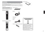
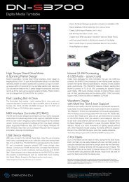
Frontpanel with controls<br />
1<br />
2<br />
3<br />
4<br />
5<br />
6<br />
7<br />
8<br />
9<br />
X Y<br />
14<br />
10<br />
11<br />
12<br />
15 16<br />
13<br />
®<br />
RODEC<br />
17 18 19<br />
1) Input select switch<br />
This selector is used to select the input signal: MICRO, PHONO, LINE A or LINE B.<br />
20<br />
21<br />
22<br />
23<br />
24<br />
25<br />
26<br />
27<br />
28<br />
29<br />
30<br />
7
2) Input level potentiometer<br />
With this control the input level of each input channel can be set.<br />
3) Equalizer controls<br />
These controls regulate Treble, Middle and Bass levels.<br />
d<br />
B<br />
r<br />
+14<br />
+12<br />
+10<br />
+8<br />
+6<br />
+4<br />
+2<br />
+0<br />
-2<br />
-4<br />
-6<br />
-8<br />
-10<br />
-12<br />
-14<br />
-16<br />
-18<br />
-20<br />
-22<br />
-24<br />
LOW MAX<br />
LOW MIN<br />
MID MAX<br />
20 50 100 200 500 1k 2k 5k 10k 20k<br />
Hz<br />
MID MIN<br />
HIGH MAX<br />
4) Input channel effects assign indication LED’s<br />
These LED’s indicate which channel is routed trough one of the effects outputs. If the FX-1 and<br />
FX-2 LED’s do not light up, no channel is routed via the effects. If the FX-1 LED of a channel<br />
lights up green, that channel is routed via effects output 1. If the FX-1 LED of a channel lights<br />
up red, one of the other channels is routed via FX-1 and no other channel can be routed via<br />
FX-1 at that moment.<br />
Same counts for the FX-2 LED that lights up. If the FX-1 LED is blinking red, the input channel<br />
effects assign potentiometer (5) must be turned back to its center position because it was<br />
initially placed in a fault position.<br />
5) Input channel effects assign potentiometer<br />
With this control, the input signal can be routed via effects output 1 or 2. When the knob is<br />
placed in the center (12 o’clock) position, the signal goes straight to the main mix without<br />
passing via one of the effects-outputs. When the knob is turned to the left, the signal will go via<br />
the effects 1 output. When the knob is turned to the right, the signal will go via the effects 2<br />
output. The proportion between the dry (no effect) and wet (100% effect) can be set with the<br />
potentiometer.<br />
HIGH MIN<br />
6) Balance control<br />
The balance between Left and Right channel is adjusted by using this knob. When it is set to<br />
the center position, the gain is the same for both channels. When turned to the left, the right<br />
channel will decrease. When turned to the right, the left signal will decrease.<br />
7) Routing selector<br />
With this selector the signal can be lead: to the left side of the crossfader (X), directly to the<br />
output (MIX) or to the right side of the crossfader (Y).<br />
8
8) PFL switches<br />
With these switches you can select the different input sources for the headphones.<br />
9) Channel faders<br />
Volume control for every input channel.<br />
10) Equalizer<br />
Triple tone control for DJ microphone.<br />
d<br />
B<br />
r<br />
+15<br />
+12.5<br />
+10<br />
+7.5<br />
+5<br />
+2.5<br />
+0<br />
-2.5<br />
-5<br />
-7.5<br />
-10<br />
-12.5<br />
-15<br />
-17.5<br />
-20<br />
-22.5<br />
-25<br />
-27.5<br />
LOW MAX<br />
LOW MIN<br />
MID MAX<br />
MID MIN<br />
HIGH MAX<br />
HIGH MIN<br />
-30<br />
20 50 100 200 500 1k 2k 5k 10k 20k<br />
Hz<br />
11) DJ microphone input level potentiometer<br />
Control for accurate level-adjustment of different types of microphones.<br />
12) Talk-over control<br />
Control for the amount of music suppression controlled by the DJ microphone signal.<br />
13) VU meters<br />
The two meters indicate the PFL signal. When no PFL-switch (8) is pressed, the VU-meter<br />
displays the mixed signal.<br />
14) Crossfader<br />
With this fader you can easily fade over between the channels with routing-selector (7) on Xposition<br />
and the channels with routing-selector (7) on Y-position. When the knob is turned<br />
completely to the left, the signal of the channels with routing selector (7) on X will appear on the<br />
output. When the knob is turned completely to the right, the signal of the channels with Routing<br />
selector (7) on Y will appear on the output. In between there will be a mix of both signals.<br />
15) DJ microphone fader<br />
Volume control for DJ microphone<br />
16) DJ microphone PFL switch<br />
With this switch the microphone signal can be made audible in the headphones and made<br />
visible on the left VU-meters.<br />
9
17) Pan Mic<br />
Panoramic control for DJ microphone input. With this button you can position the microphone<br />
signal between the left and right loudspeaker.<br />
18) Power "ON" indicators<br />
These indicators light up when the power is on.<br />
19) Master fader<br />
Volume controls final output of mixer towards slave or integrated amplifiers.<br />
20) Monitor output potentiometer<br />
Volume control for the signal level for the monitor output, this output does not contain the DJmic<br />
signal to avoid feedback of the microphone-signal via the monitor loudspeakers.<br />
21) Monitor equalizer controls<br />
Bass and treble adjustment for the monitor output.<br />
d<br />
B<br />
r<br />
+20<br />
+18<br />
+16<br />
+14<br />
+12<br />
+10<br />
+8<br />
+6<br />
+4<br />
+2<br />
-0<br />
-2<br />
-4<br />
-6<br />
-8<br />
-10<br />
-12<br />
-14<br />
-16<br />
-18<br />
LOW MAX<br />
LOW MIN<br />
-20<br />
20 50 100 200 500 1k 2k 5k 10k 20k<br />
Hz<br />
22) Monitor mode Switch<br />
This switch is used to set the monitor output in mono or stereo mode.<br />
23) Master 1 mode Switch<br />
This switch is used to set the master 1 output in mono or stereo mode.<br />
24) Record Select<br />
This switch is used to make recordings with or without the DJ microphone.<br />
+ DJ MIC: in this position you add the DJ mic signal to the music.<br />
- DJ MIC: in this position you only record the signal from channel 1 - 4.<br />
This switch has no influence on the master outputs.<br />
HIGH MAX<br />
25) Main mix effects assign indication LED’s<br />
These LED’s indicate if the main mix signal is routed through one of the effects outputs. If the<br />
FX-1 and FX-2 LED’s do not light up, the main mix signal is not routed via the effects. If the FX-<br />
HIGH MIN<br />
10
1 LED lights up green, the main mix signal is routed via effects output 1. If the FX-1 LED lights<br />
up red, an input channel’s signal is routed via FX-1 output and no other channel can be routed<br />
via FX-1 at that moment.<br />
Same counts for the FX-2 LED that lights up. If the FX-1 LED is blinking red, the main mix<br />
effects assign potentiometer (26) must be turned back to its center position because it was<br />
initially placed in a fault position.<br />
26) Main mix effects assign potentiometer<br />
With this control, the main mix signal can be routed through effects output 1 or 2. When the<br />
knob is placed in the center (12 o’clock) position, the signal goes straight to the main mix<br />
without passing through one of the effects-outputs. When the knob is turned to the left, the<br />
signal will go through the effects 1 output. When the knob is turned to the right, the signal will<br />
go through the effects 2 output. The proportion between the dry (no effect) and wet (100%<br />
effect) can be set with the potentiometer.<br />
27) Headphones-select potentiometer<br />
With this potentiometer, the signal for the headphones output can be selected. When turned<br />
completely to the left, the signal selected with the channel PFL-switches (8) appears on the<br />
headphones. When turned completely to the right, the mix-signal appears on the headphones.<br />
In between it results in a mix of the PFL-signal and the mix-signal.<br />
28) Headphones volume control<br />
The volume of the headphones can be adjusted with this knob.<br />
WARNING! The sound and intensity volume of the headphones amplifier can be very<br />
strong and, if not used properly, or if used in too close proximity, can cause<br />
permanent or temporary damage to one’s hearing, perhaps even deafness.<br />
Please use with caution and common sense!<br />
29) Phones output<br />
Output for high level headphones monitoring. With the PFL switches (8) and the headphonesselect<br />
potentiometer (27), the connected audio sources or the main-mix can be made audible<br />
without manipulating the output signal (Headphones 32-600Ω).<br />
ATTENTION! Always turn headphones volume to “0” (fully counter clockwise) BEFORE<br />
putting the headphones on your or somebody else her/his ears! Then<br />
slowly raise the volume by turning the volume knob in clockwise direction.<br />
30) Cross fader curve potentiometer<br />
This potentiometer is used to set the sharpness of the cross fader. When the potentiometer is<br />
turned completely to the left, the cross fader (14) will react as a normal cross fader. The<br />
volumes of the channels with routing-selector (7) on Y-position will rise from 0 to maximum<br />
when the shaft of the cross fader is moved from the left to the middle. The same counts for the<br />
volumes of the channels with routing-selector (7) on X-position, but then from the right side to<br />
the middle.<br />
11
When the curve potentiometer is turned to the right, the cross fader will react very fast, with the<br />
volumes of the channels with routing-selector (7) on Y-position rising from 0 to maximum when<br />
the shaft of the cross fader is moved from the left to a few fractions from the left. The same<br />
counts for the volumes of the channels with routing-selector (7) on X-position, but then from the<br />
right side to a few fractions from the right side.<br />
12
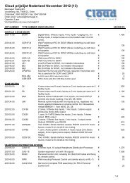
Backpanel with connectors<br />
H<br />
I<br />
J<br />
K<br />
PS<br />
E<br />
A<br />
B<br />
C D E<br />
®<br />
RODEC<br />
www.<strong>rodec</strong>.com<br />
F G<br />
L M N O P Q R S<br />
Professional<br />
Audio<br />
Equipment<br />
Made in<br />
Belgium<br />
WARNING<br />
DISCONNECT<br />
POWERCORD<br />
BEFORE OPENING<br />
A) Power switch<br />
Controls the supply of AC power to the set. A single push turns on the mixing panel, a second<br />
push turns it off.<br />
Attention! By turning off this switch, the mixing panel is in stand-by mode. At that moment<br />
the mixing panel will still consume electricity from the mains net. The power<br />
cord has to be unplugged from the power inlet to shut down all power.<br />
B) Power inlet<br />
Universal mains power inlet.<br />
C) DJ microphone input<br />
Balanced microphone input with a sensitivity of 4.2mV, with XLR-JACK combination connector.<br />
D) Effects IN/OUT<br />
Input and output to connect effect equipment to the microphone channel. If there is no plug in<br />
the JACK connector, the microphone channel works normally, if there is a plug inserted in the<br />
JACK, the internal link is interrupted. The sensitivity of this IN/OUT connection is 775mV.<br />
E) Ground-terminal<br />
Terminal to connect the ground wire of the vinyl turntable.<br />
F) Micro input<br />
Balanced microphone input. To obtain good signal quality, you have to use a microphone with<br />
balanced output. The use of a microphone without balanced output is also possible.<br />
G) PHONO input<br />
Phono input with a sensitivity of 5.2mV and built in RIAA correction.<br />
13
d<br />
B<br />
r<br />
+20<br />
+18<br />
+16<br />
+14<br />
+12<br />
+10<br />
+8<br />
+6<br />
+4<br />
+2<br />
-0<br />
-2<br />
-4<br />
-6<br />
-8<br />
-10<br />
-12<br />
-14<br />
-16<br />
-18<br />
-20<br />
20 50 100 200 500 1k 2k 5k 10k 20k<br />
Hz<br />
H) Effects IN/OUT 1<br />
In- and output to connect effect equipment to the music signal. The signal that runs through this<br />
connector is controlled by the input channel effects assign potentiometer (5) or main mix effects<br />
assign potentiometer (26). Internally linked when JACK is not inserted. Sensitivity 775mV.<br />
I) Effects IN/OUT 2<br />
In- and output to connect effect equipment to the music signal. The signal that will run through<br />
this connector is controlled by the input channel effects assign potentiometer (5) or main mix<br />
effects assign potentiometer (26). Internally linked when JACK is not inserted. Sensitivity<br />
775mV.<br />
J) Second headphones connector<br />
Signal identical as headphones-output on the frontpanel (29). The specifications are the same<br />
as the headphones output on the frontpanel.<br />
K) Asymmetrical master output<br />
Asymmetrical output to connect a power-amplifier. The output level can be manipulated with<br />
master fader (19) from 0 to maximum (0.775V).<br />
L) Symmetrical monitor output<br />
Additional output up to 1.55V controlled by monitorpotentiometer (20). The DJ-microphone<br />
signal does not appear on this output.<br />
M) Symmetrical master output<br />
Symmetrical output to connect a power-amplifier or loudspeaker-processor. The output level<br />
can be manipulated with master fader (19) from 0 to maximum (1.55V).<br />
14
N) Analogue line input A<br />
Analogue asymmetrical input with a sensitivity of 500mV, to connect different equipment such<br />
as a CD player, MD player, DVD player, MP3-player, HD-player, analogue - or digital tuner,<br />
cassette player or video player.<br />
O) Analogue recording output<br />
Output to connect analogue recording device or (HIFI) video recorders to make recordings. This output<br />
can be switched with or without recording the DJ microphone signal (24). (Only provided on channels 2,<br />
3 and 4)<br />
P) Analogue line input B<br />
Analogue asymmetrical input with a sensitivity of 500mV, to connect different equipment such<br />
as a CD player, MD player, DVD player, MP3-player, HD-player, analogue - or digital tuner,<br />
cassette player or video player. (Only provided on channels 2, 3 and 4)<br />
Q) Digital recording output<br />
Output to connect to a S/P DIF input of a MD-recorder, CD-recorder, HD-recorder or DATrecorder<br />
to make recordings. This output can be switched with or without recording the DJ<br />
microphone signal (24). Both signals (left and right) go through one connector. (Only provided<br />
on channels 1 and 5)<br />
R) USB input/output<br />
Optional USB connector to play music from PC or HD-player and simultaneously record the<br />
main mix signal with a PC or HD-recorder. All 4 signals (reproduction left and right and<br />
recording left and right) go through one connector. (Only possible on channels 1 and 5)<br />
S) Digital line input B<br />
Digital S/P DIF input, to connect different equipment such as a CD player, MD player, DVD<br />
player, MP3-player, HD-player or digital tuner. Both signals (left and right) go through one<br />
connector. (Only provided on channels 1 and 5)<br />
Please use signal cables shorter than 1 meter for the inputs and the outputs.<br />
15
Cable configurations<br />
a) Different audio connectors<br />
Sleeve<br />
RCA (Cinch) male JACK 3 pole 1/4 inch male<br />
USB A male<br />
USB B male<br />
PHOENIX 4 pole female<br />
b) Different audio cables<br />
Pin 1<br />
Pin 4<br />
1) Asymmetrical RCA cable:<br />
Tip<br />
Pin 4 Pin 3 Pin 2<br />
Pin 1<br />
RCA male<br />
Asymmetrical<br />
Pin 3<br />
Pin 2<br />
JACK 2 pole 1/4 inch male<br />
XLR 3 pole female<br />
XLR 3 pole male<br />
Sleeve<br />
Sleeve<br />
RCA male<br />
Asymmetrical<br />
Used for connections between: CD-player, MD-player/recorder, Vinyl turntable, DVDplayer/recorder,<br />
amplifier, etc. and mixing panel.<br />
For connections of analogue signals, you need 2 of these cables for stereo<br />
For connections of digital S/P DIF, you need only 1 cable for stereo<br />
2) Symmetrical XLR cable:<br />
XLR 3 pole female<br />
Symmetrical<br />
1<br />
2 3<br />
XLR 3 pole male<br />
Symmetrical<br />
Ring<br />
Pin 2<br />
Pin 1<br />
Pin 3<br />
Pin 3<br />
Used for connections between: microphone, amplifier, equalizer, loudspeaker-processor, limiter,<br />
etc. and mixing panel.<br />
For connections of analogue signals, you need 2 of these cables for stereo<br />
1 2<br />
3<br />
Tip<br />
Tip<br />
Pin 1<br />
Pin 2<br />
16
3) Symmetrical XLR female to JACK 3pole male cable:<br />
XLR 3 pole female<br />
Symmetrical<br />
1<br />
2 3<br />
JACK 3 pole 1/4 inch male<br />
Symmetrical<br />
Used for connections between: microphone, amplifier, loudspeaker-processor, etc. and mixing<br />
panel.<br />
For stereo connections, you need 2 of these cables<br />
4) Asymmetrical JACK 2 pole male to RCA male cable:<br />
JACK 2 pole 1/4 inch male<br />
Asymmetrical<br />
RCA male<br />
Asymmetrical<br />
Used for connections between: electronic musical instrument, synthesizer, sampler, effectsmachine,<br />
amplifier, recorder, etc. and mixing panel.<br />
For stereo connections, you need 2 of these cables<br />
5) Symmetrical XLR female to asymmetrical RCA male cable:<br />
XLR 3 pole female<br />
Symmetrical<br />
2 1<br />
3<br />
RCA male<br />
Asymmetrical<br />
Used for connections between: professional CD-player, professional MD-player, sampler, effectsmachine,<br />
etc. and mixing panel.<br />
For stereo connections, you need 2 of these cables<br />
6) Asymmetrical RCA male to symmetrical XLR male cable:<br />
RCA male<br />
Asymmetrical<br />
XLR 3 pole male<br />
Symmetrical<br />
Used for connections between: professional recorder, sampler, effects-machine, amplifier, etc. and<br />
mixing panel.<br />
For stereo connections, you need 2 of these cables<br />
1 2<br />
3<br />
17
7) JACK 3 pole 1/4 inch male to 2 times JACK 2 pole 1/4 inch male (Y-split) cable:<br />
JACK 3 pole 1/4 inch male<br />
Symmetrical<br />
JACK 2 pole 1/4 inch male<br />
Asymmetrical<br />
JACK 2 pole 1/4 inch male<br />
Asymmetrical<br />
Used for connections between: effects-machine, audio-filter, delay-loop, etc. and mixing panel.<br />
For stereo connections, you need 2 of these cables.<br />
The upper 2 pole JACK is the signal send cable, this has to be connected to the input of the effectsmachine.<br />
The lower 2 pole JACK is the signal return cable, this has to be connected to the output of the<br />
effects-machine.<br />
8) JACK 3 pole 1/4 inch male to 2 times RCA male (Y-split) cable:<br />
JACK 3 pole 1/4 inch male RCA male<br />
Symmetrical Asymmetrical<br />
RCA male<br />
Asymmetrical<br />
Used for connections between: effects-machine, audio-filter, delay-loop, etc. and mixing panel.<br />
For stereo connections, you need 2 of these cables<br />
The upper RCA is the signal send cable, this has to be connected to the input of the effectsmachine.<br />
The lower RCA is the signal return cable, this has to be connected to the output of the effectsmachine.<br />
18
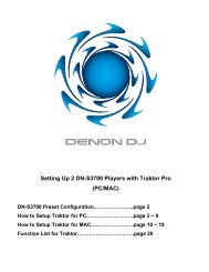
Operating instructions<br />
For correct operation of the mixing panel, please follow the instructions below.<br />
1) Before connecting anything to the mixing panel, be sure all equipment is turned off. Then<br />
connect the different audio sources, amplifiers, effects-units, headphones, etc.. Next step is to<br />
turn on the audio sources and effects-units.<br />
When all these units are in ready state, you can switch on the power switch (A) of the mixing<br />
panel. The power indicators (18) will light up.<br />
After 5 seconds, you can turn on the loudspeaker processors and amplifiers.<br />
EFFECTS MACHINE<br />
®<br />
RODEC<br />
RE<br />
®<br />
RODEC<br />
RE<br />
filtertechnol ogy ins ide<br />
filtertechnol ogy ins ide<br />
EFFECTS MACHINE<br />
L<br />
R<br />
L<br />
R<br />
HEADPHONES<br />
PS<br />
E<br />
ACTIVE BOOTH<br />
MONITORS<br />
L<br />
R<br />
DJ<br />
MICROPHONE<br />
L<br />
R<br />
LOUDSPEAKER<br />
PROCESSOR<br />
TO MAIN<br />
AMPLIFIERS<br />
REVERB<br />
PROCESSOR<br />
®<br />
RODEC<br />
www.<strong>rodec</strong>.com<br />
PHONO<br />
TURNTABLE<br />
DVD-PLAYER<br />
L<br />
R<br />
PHONO<br />
TURNTABLE<br />
L R L R L R L R<br />
L<br />
R<br />
PROFESSIONAL<br />
DOUBLE CD PLAYER<br />
SUB MIXER<br />
SESSION/ IN P U T 1 IN P U T 2 OUTPUTS<br />
AU X IN<br />
PHONO 1<br />
PHONO 2<br />
LEVEL<br />
SELECT<br />
STRAIGHT<br />
SEL ECT<br />
M ASTER<br />
RO UTIN G<br />
REVERSE<br />
1<br />
LINE 1<br />
LINE 2<br />
0 MAX<br />
0 MAX<br />
MIX L/CH1 M IX R/C H2<br />
CHANNEL 3 CHANNEL 1<br />
+5<br />
CHANNEL 2<br />
MIC 3<br />
+3<br />
IN PUT<br />
+1<br />
M ASTER<br />
SELECT<br />
2<br />
0dB<br />
LINE 3<br />
-1<br />
0 MAX<br />
0dB<br />
-3<br />
-5<br />
-10<br />
LEVEL<br />
LEVEL<br />
-20<br />
LEVEL<br />
PFL MI X<br />
POWER<br />
0 MAX<br />
0 MAX<br />
0 MAX<br />
VU<br />
CH 1<br />
SELECT<br />
CH 2<br />
0<br />
EQUALIZER<br />
EQ UALIZ ER<br />
EQ HIG H<br />
+<br />
+ +<br />
+<br />
- +<br />
0<br />
0<br />
0 0<br />
0<br />
EQ LOW<br />
-<br />
- -<br />
-<br />
LO W MID HIGH<br />
LOW MID HIGH<br />
- +<br />
WET<br />
PFL<br />
FX-INSERT<br />
FX-IN SERT<br />
L<br />
R<br />
L<br />
R<br />
ROUTIN G<br />
BALANC E<br />
CH 1 MIX CH 2<br />
CU T<br />
L<br />
DRY<br />
FX-INSERT MIX<br />
®<br />
RODEC<br />
NORM AL NO RM AL<br />
R<br />
BALANC E<br />
REVERSE RE VE RS E<br />
MONO<br />
MODE<br />
PFL<br />
CH 1- 2<br />
CU T<br />
PFL C H1 - CH2 SELECT<br />
CH 1<br />
CH 2<br />
DAB RECIEVER<br />
MASS STORAGE<br />
PLAYER<br />
PC BASED MUSIC<br />
PLAYER/RECORDER<br />
2) Connect the headphones to the headphones JACK connector (29) or (J). Use headphones with<br />
impedance between 32 and 600Ω.<br />
ATTENTION! Always turn headphones volume to “0” (fully counter clockwise) BEFORE<br />
putting the headphones on your or somebody else her/his ears! Then slowly<br />
raise the volume by turning the volume knob in clockwise direction.<br />
3) Choose with the input select switch (1) the right audio-source.<br />
Professional<br />
Audio<br />
Equipment<br />
Made in<br />
Belgium<br />
WARNING<br />
DISCONNECT<br />
POWERCORD<br />
BEFORE OPENING<br />
19
4) Switch the PFL button (8) in position ON to listen at the desired source. Turn the phones select<br />
button (27) completely to the left and turn the phones volume potentiometer (28) to the desired<br />
position to get the stereo signal on the headphones and the two left VU-meters. The PFL circuit<br />
works as a sum-system, there is a possibility to listen to more sources at the same time. All<br />
these operations have no influence on the output signal! Adjust with the level control (2) the<br />
input signal until the red indicators of the level meters (13) will light up occasionally. Adjust if<br />
necessary the quality of the sound with the equalizer (3).<br />
LOOK OUT: The equalizer at each input is used to manipulate the sound of each of the<br />
input sources. To correct the acoustic of the room it is probably best to use an<br />
external equalizer.<br />
5) To send the input signal through one of the effects outputs, first check if the desired effects bus<br />
is free. This can be done by checking the input channel effects assign indication LED’s (4). If<br />
the FX-1 LED does not light up, the FX-1 bus is free. If the FX-2 LED does not light up, the FX-<br />
2 bus is free. If one of the LED’s is blinking red, the input channel effects assign potentiometer<br />
(5) is in a wrong position. Then first turn the input channel effects assign potentiometer to its 12<br />
o’ clock position, so the LED will stop blinking. To select the FX-1 bus, turn the input channel<br />
effects assign potentiometer to the left, first, no effect will be audible, but the influence of the<br />
effect will increase when the potentiometer is turned further to the left. When the potentiometer<br />
is completely to the left, 100% of the signal will be influenced by the effect.<br />
The same procedure can be followed to select FX-2, but then the potentiometer has to be<br />
turned to the right.<br />
When the FX-1 bus is selected, the according LED will light up green, same for the FX-2 bus.<br />
On the other input channels and on the main mix, the according LED will light up red, to<br />
indicate the according effects-bus is occupied.<br />
NO EFFECT SELECTED<br />
EFFECT SELECT POTENTIOMETER 1 ON WRONG POSITION<br />
BLINKING RED<br />
EFFECT 1 SELECTED ON CHANNEL 1<br />
GREEN<br />
FX 1 SELECTED ON CH 1 AND FX 2 SELECTED ON CH 3<br />
GREEN RED RED<br />
RED RED<br />
GREEN<br />
FX 1 SELECTED ON CH 1 AND<br />
CH 2 POTENTIOMETER ON WRONG POSITION<br />
GREEN<br />
RED<br />
BLINKING RED<br />
RED<br />
RED<br />
NO SIGNAL<br />
®<br />
RODEC<br />
RE<br />
NO SIGNAL<br />
®<br />
RODEC<br />
RE<br />
SIGNAL OF CHANNEL 1<br />
®<br />
RODEC<br />
RE<br />
SIGNAL OF CHANNEL 1<br />
®<br />
RODEC<br />
RE<br />
SIGNAL OF CHANNEL 1<br />
®<br />
RODEC<br />
filtertechnology inside<br />
filtertechnology inside<br />
filtertechnology inside<br />
filtertechnology inside<br />
filtertechnology inside<br />
6) Open up the fader (9) of the chosen input channel<br />
RE<br />
L<br />
R<br />
L<br />
R<br />
L<br />
R<br />
L<br />
R<br />
L<br />
R<br />
L<br />
R<br />
L<br />
R<br />
L<br />
R<br />
L<br />
R<br />
L<br />
R<br />
NO SIGNAL<br />
®<br />
RODEC<br />
NO SIGNAL<br />
NO SIGNAL<br />
SIGNAL OF CHANNEL 2<br />
NO SIGNAL<br />
7) Slide up master fader (19) till desired volume is reached. Also open the monitor potentiometer<br />
(20), to hear the music at the DJ-booth.<br />
RE<br />
®<br />
RODEC<br />
RE<br />
®<br />
RODEC<br />
RE<br />
®<br />
RODEC<br />
RE<br />
®<br />
RODEC<br />
RE<br />
f i l t e r t e c h n o l o g y i n s i d e<br />
f i l t e r t e c h n o l o g y i n s i d e<br />
f i l t e r t e c h n o l o g y i n s i d e<br />
f i l t e r t e c h n o l o g y i n s i d e<br />
f i l t e r t e c h n o l o g y i n s i d e<br />
20
8) The music in the DJ-booth can be manipulated with the monitor equalizer (21).<br />
9) Correct if necessary the balance with button (6), for monophonic sound on master output set<br />
switch (23) in mono position. For monophonic sound on monitor output, set switch (22) in mono<br />
position.<br />
10) If you like to use the crossfader (14), you can route the channel to the left (X) side of the<br />
crossfader by putting the routing switch (7) on CF-X position. Or to the right (Y) side of the<br />
crossfader when you put the routing switch (7) on the CF-Y position. The response curve of the<br />
cross fader (14) can be adjusted with the cross fader curve potentiometer (30).<br />
11) To change the source, repeat point 3) to 6).<br />
12) By turning the headphones select potentiometer (27) more clockwise, you will increase the<br />
amount of the main mix signal in the headphones.<br />
13) To add a microphone signal, connect the microphone to the MIC input (C). Turn the level<br />
control (11) and the talk-over (12) to zero, slide up the MIC fader (15) to maximum and adjust<br />
with the level button (11) the volume of the microphone. Adjust with the equalizer (10) the<br />
sound of the microphone. To use the talk over, adjust the talk over button (12) (0= no decrease,<br />
10= total decrease). With the pan MIC (17), the DJ microphone signal can be placed<br />
somewhere between left and right. Eventually you can connect an external processor<br />
(example: compressor or reverb) to the effects insert (D) of the microphone channel.<br />
14) The mixed signal can be recorded, simply by connecting a recorder to the analogue (O) or<br />
digital (Q) record-connectors. Depending on the position of the record-select switch (24) you<br />
can decide if the microphone signal is also recorded or not. The mixed signal can also be<br />
recorded with a computer through the optional USB connector (R).<br />
15) The main mix signal can also be lead to one of the effects insert outputs. This can be done in<br />
the same way as leading the signal of an input channel to the effects insert outputs, follow the<br />
instructions of point 5). The effects assign indication LED’s for the main mix are LED’s (25). The<br />
effects assignation for the main mix can be done with the main mix effects assign potentiometer<br />
(26).<br />
16) When no PFL is selected with the PFL switches on the input channels (7), the mixed signal will<br />
appear on the VU-meters. If you like to compare via the VU-meters the pre-fade signal with the<br />
output signal, you can do this by switching all PFL switches off first. Then switch the PFL switch<br />
of the input channel you wish to compare with the mixed signal, on an off. In that way, both<br />
signal levels can be compared.<br />
SUBSONIC FILTER<br />
The two master outputs and the monitor output have a subsonic filter to protect the bass loudspeakers<br />
from DC and subsonic signals. This filter cannot be switched off. The filter gives a reduction of 25dB at<br />
10Hz.<br />
21
Application examples<br />
Drive in<br />
LAPTOP<br />
COMPUTER<br />
PROFESSIONAL<br />
PC-MUSIC PLAYER<br />
CONTROLLER<br />
AUDIO MODULATED LIGHTS<br />
PROFESSIONAL<br />
DOUBLE CD PLAYER<br />
X Y<br />
DANCE FLOOR<br />
DJ<br />
MICROPHONE<br />
®<br />
RODEC<br />
EFFECTS MACHINE<br />
®<br />
RODEC<br />
RE<br />
filtertechnology ins ide<br />
DJ HEADPHONES<br />
ACTIVE<br />
MONITOR<br />
LOUDSPEAKER<br />
PROCESSOR<br />
POWER AMPLIFIERS<br />
22
Pub/resto<br />
CD PLAYER<br />
DAB RECIEVER<br />
PUBLIC AREA<br />
SUBWOOFER SUBWOOFER<br />
PC BASED MUSIC<br />
PLAYER<br />
X Y<br />
BAR<br />
DESKTOP<br />
MICROPHONE<br />
®<br />
RODEC<br />
DJ HEADPHONES<br />
POWER AMPLIFIERS<br />
LOUDSPEAKER<br />
PROCESSOR<br />
KITCHEN<br />
23
Performance at festival<br />
PUBLIC AREA<br />
SUBWOOFER<br />
LOUDSPEAKER<br />
PROCESSOR<br />
POWER<br />
AMPLIFIERS<br />
LOUDSPEAKER<br />
PROCESSOR<br />
POWER<br />
AMPLIFIERS<br />
LINE ARRAY<br />
LOUDSPEAKER<br />
PROCESSOR<br />
POWER<br />
AMPLIFIERS<br />
LOUDSPEAKER<br />
PROCESSOR<br />
POWER<br />
AMPLIFIERS<br />
LOUDSPEAKER<br />
PROCESSOR<br />
POWER<br />
AMPLIFIERS<br />
LOUDSPEAKER<br />
PROCESSOR<br />
POWER<br />
AMPLIFIERS<br />
LOUDSPEAKER<br />
PROCESSOR<br />
POWER<br />
AMPLIFIERS<br />
LOUDSPEAKER<br />
PROCESSOR<br />
POWER<br />
AMPLIFIERS<br />
LOUDSPEAKER<br />
PROCESSOR<br />
POWER<br />
AMPLIFIERS<br />
EFFECTS MACHINE<br />
®<br />
RODEC<br />
fi lt ert echnology in s i de<br />
RE<br />
STAGE<br />
PHONO TURNTABLE PHONO TURNTABLE<br />
EFFECTS MACHINE<br />
®<br />
RODEC<br />
f il te r te c hno l ogy i n s i de<br />
RE<br />
DJ HEADPHONES<br />
ACTIVE DI BOX<br />
ACTIVE DI BOX<br />
MONITOR MONITOR<br />
SUBBASS SUBBASS<br />
X Y<br />
LOUDSPEAKER<br />
PROCESSOR<br />
POWER<br />
AMPLIFIERS<br />
LOUDSPEAKER<br />
PROCESSOR<br />
POWER<br />
AMPLIFIERS<br />
LOUDSPEAKER<br />
PROCESSOR<br />
POWER<br />
AMPLIFIERS<br />
FOH + MONITOR MIXING PANEL<br />
LOUDSPEAKER<br />
PROCESSOR<br />
POWER<br />
AMPLIFIERS<br />
LINE ARRAY LINE ARRAY<br />
®<br />
RODEC<br />
SUBWOOFER<br />
SUBWOOFER SUBWOOFER<br />
LINE ARRAY<br />
LOUDSPEAKER<br />
PROCESSOR<br />
POWER<br />
AMPLIFIERS<br />
LOUDSPEAKER<br />
PROCESSOR<br />
POWER<br />
AMPLIFIERS<br />
LOUDSPEAKER<br />
PROCESSOR<br />
POWER<br />
AMPLIFIERS<br />
LOUDSPEAKER<br />
PROCESSOR<br />
POWER<br />
AMPLIFIERS<br />
24
Shop<br />
WALL MOUNTED<br />
100V SPEAKERS<br />
DRESSING<br />
CABINS LADIES<br />
100V CEILING<br />
SPEAKER<br />
100V CEILING<br />
SPEAKER<br />
100V CEILING<br />
SPEAKER<br />
100V CEILING<br />
SPEAKER<br />
SHOP AREA<br />
MULTI CD PLAYER<br />
FM/AM TUNER<br />
DAB RECIEVER<br />
CASH REGISTER<br />
X Y<br />
DESKTOP<br />
MICROPHONE<br />
®<br />
RODEC<br />
100V AMPLIFIER<br />
DRESSING<br />
CABINS MEN<br />
100V CEILING<br />
SPEAKER<br />
100V CEILING<br />
SPEAKER<br />
100V CEILING<br />
SPEAKER<br />
100V CEILING<br />
SPEAKER<br />
25
Home set-up<br />
TABLETOP<br />
CD PLAYER<br />
PHONO<br />
TURNTABLE<br />
BEDROOM<br />
AUDIO MODULATED LIGHTS<br />
LAPTOP<br />
COMPUTER<br />
EXTERNAL<br />
MULTICHANNEL<br />
SOUNDCARD<br />
X Y<br />
HIFI AMPLIFIER<br />
PHONO<br />
TURNTABLE<br />
DJ MICROPHONE<br />
®<br />
RODEC<br />
EFFECTS MACHINE<br />
®<br />
RODEC<br />
RE<br />
filtertechnology inside<br />
DJ HEADPHONES<br />
26
Options<br />
1) USB I/O set MX00<br />
Optional input/output kit to connect the mixing panel with a computer. The USB connector<br />
contains 1 stereo input signal and 1 stereo record output signal. With this option music can be<br />
played from a computer via USB. Simultaneous the mixed music can be recorded via the<br />
computer. The option must be built in as follows: First pull off the fader knobs (9, 14, 15 & 19) at<br />
the frontpanel. Then unscrew the aluminum fader cover plate (4 screws). Take of this aluminum<br />
plate. Then unscrew the bottombox, 2 screws at the frontpanel, one screw at each side and 2<br />
screws at the bottom.<br />
Screw of the hole cover plate (at the backpanel) which covers the desired hole for the USB<br />
option set. Place the USB option so that the 6 pole angled connector on the USB PCB fits in<br />
the 6 pole angled connector on the input PCB. Screw the screw in the hole in the backpanel to<br />
mount the USB option kit. Close the mixing panel again by replacing the bottombox (6 screws),<br />
the aluminum fader cover plate (4 screws) and the fader knobs (6 pieces).<br />
Connect the USB I/O set to a computer via a USB-cable. The computer will recognize the USB<br />
I/O set. Select the USB I/O set as playback- and recording device in the sound and audio<br />
configuration menu of the computer or audio-software.<br />
The USB I/O set MX00 can be ordered at every authorized RODEC-dealer.<br />
Order code: 94 001 0070<br />
2) Digital optical input channel fader MX00 set<br />
Users can upgrade their mixing panel with digital faders on the music input channels. The<br />
digital faders replace the standard analogue faders. The option must be built in as follows: First<br />
pull off the fader knobs (9, 14, 15 & 19) at the frontpanel. Then unscrew the aluminum fader<br />
cover plate (4 screws). Take of this aluminum plate. Unscrew the channel fader, which you like<br />
to replace (2 screws). Pull off the 4 pole flat cable at the input PCB. Place the 10 pole flatcable<br />
(delivered together with the digital optical input channel fader set) on the 10 pole connector<br />
(right below the PFL switch) on the input channel PCB. Connect the other side of the flatcable<br />
to the digital optical input channel fader. Screw the fader to the frontpanel (2 screws), attention,<br />
the 10 pole connector on the fader PCB must be placed at the side of the crossfader (14).<br />
Replace the aluminum fader cover plate and fader knobs. The digital optical input channel fader<br />
is ready to use.<br />
The digital optical input channel fader MX00 set can be ordered at every authorized RODECdealer.<br />
Order code: 94 001 0072<br />
3) Digital optical crossfader MX00 set<br />
The standard analogue crossfader can be upgraded by a digital optical crossfader. The option<br />
must be built in as follows: First pull off the fader knobs (9, 14, 15 & 19) at the frontpanel. Then<br />
unscrew the aluminum fader cover plate (4 screws). Take of this aluminum plate. Then unscrew<br />
the bottombox, 3 screws at the frontpanel, one screw at each side and 3 screws at the bottom.<br />
Unscrew the crossfader (2 screws). Pull off the 4-pole flatcable of the crossfader on the output<br />
PCB. Place the 10 pole flatcable (delivered together with the digital optical crossfader set on<br />
the 10 pole connector on the output PCB. Connect the other side of the flatcable to the digital<br />
optical crossfader. Screw the digital optical crossfader to the frontpanel (2 screws), attention,<br />
the 10 pole connector on the fader PCB must be placed at the opposite side of the output PCB.<br />
Replace the bottombox (6 screws), the aluminum fader cover plate (4 screws) and fader knobs.<br />
The digital optical cross fader is ready to use.<br />
The digital optical cross fader MX00 set can be ordered at every authorized RODEC-dealer.<br />
Order code: 94 001 0073<br />
27
4) Standard knobs set MX00 series<br />
The knobs of a MX00 series mixing panel can be ordered in a set. For a MX1400 you need 1 of<br />
these sets to replace all the knobs.<br />
The standard knobs set MX00 series can be ordered at every authorized RODEC-dealer.<br />
Order code: 94 001 0074<br />
5) Fader knobs BX/CX/MX MKIII/MX00 series<br />
The fader knobs of a MX00 series mixing panel can be ordered in a set. For a MX1400 you<br />
need 1 of these sets to replace all the fader knobs.<br />
The fader knobs BX/CX/MX MKIII/MX00 series can be ordered at every authorized RODECdealer.<br />
Order code: 94 001 0041<br />
28
Specifications<br />
0dBm = 0.775V RMS<br />
Nominal analogue input levels:<br />
- Line A asymmetrical (RCA): 500mV / 50kΩ<br />
- Line B asymmetrical (RCA): 500mV / 50kΩ<br />
- Phono asymmetrical (RCA gold plated): 5.2mV / 50kΩ<br />
- Microphone (channel 1 – 4) symmetrical (XLR): 9.1mV / 3.6kΩ<br />
- Microphone symmetrical (XLR or ¼” TRS JACK): 4.2mV / 1.8kΩ<br />
- Effects return (1/4” TRS JACK): 775mV / 10kΩ<br />
- Priority in (optional) (RCA): 500mV / 1.5kΩ<br />
Nominal analogue output levels:<br />
- Master 1 asymmetrical (RCA): 775mV / 10kΩ<br />
- Master 1 symmetrical (XLR): 1.55V / 600Ω<br />
- Monitor symmetrical (XLR): 1.55V / 600Ω<br />
- Record asymmetrical (RCA): 500mV / 10kΩ<br />
- Effects send asymmetrical (1/4” TRS JACK): 775mV / 10kΩ<br />
- Headphones (1/4” TRS JACK):<br />
- 8Ω: (1kHz – 1%THD) 417mW (1.8V) / 1.1W music power<br />
- 32Ω: (1kHz – 1%THD) 1.0W (5.7V) / 1.7W music power<br />
- 600Ω: (1kHz – 1%THD) 520mW (17.7V) / 0.6W music power<br />
Digital input:<br />
- Line B (RCA): S/P DIF IEC 958 type II 32kHz – 192kHz<br />
- USB (optional): 32kHz - 48kHz 16bit<br />
Digital output:<br />
- Record (RCA): S/P DIF IEC 958 type II 44.1kHz<br />
- USB (optional): 11.025kHz - 48kHz 16bit<br />
Signal headroom: 20.0dB @ 1kHz / THD < 0.05%<br />
Crosstalk:<br />
- Left to right of an input channel: >60dB @ 1kHz<br />
- Channel to channel: >86dB @ 1kHz<br />
Frequency response: +/- 0.25 dB from 20Hz to 20kHz<br />
Subsonic filter: -25dB at 10Hz<br />
Dynamic range: 103dB<br />
Signal to noise ratio: 90dB<br />
Total harmonic distortion: < 0.006%<br />
29
Music equalizer: - Low: +10dB / -21dB at 100Hz<br />
- Mid: +10dB / -21dB at 1kHz<br />
- High: +10dB / -21dB at 10kHz<br />
Microphone equalizer: - Low: +/- 12dB at 100Hz<br />
- Mid: +/- 12dB at 1kHz<br />
- High: +/- 12dB at 10kHz<br />
Monitor output equalizer: - Low: +12dB / -12dB at 100Hz<br />
- High: +12dB / -12dB at 10kHz<br />
Power supply voltage: 90VAC – 264VAC<br />
Power supply frequency: 47Hz – 63Hz<br />
Power consumption: 38W (On), 60W (Full load), 6W (Stand by)<br />
Operating temperature: 0°C (32°F) – 40°C (104°F)<br />
Operating humidity: 5% - 90% (no condensation)<br />
Mechanical specifications:<br />
Frontpanel dimensions (W x D): 320.0mm (12.6”) x 355.0mm (14.0“) (8HE)<br />
Bottombox dim. (W x D x H): 312.0mm (12.3“) x 343.0mm (13.5“) x 110.0mm (4.3“)<br />
Panel cut out dimensions (W x D): 316.0mm (12.4“) x 347.0mm (13.7“)<br />
Packed box dimensions (W x D x H): 335mm (13.2“) x 414mm (16.3“) x 207mm (8.1“)<br />
Weight: 4.50kg (9.92lbs)<br />
Packed weight: 5.46kg (12.04lbs)<br />
30
Explanatory words list<br />
Amplitude: The amplitude is the size, the strength of a vibration. This can be a mechanical vibration,<br />
for example a snare of a guitar, or the, from that arisen, sound wave or from any other cyclical varying<br />
appearance in time. Because any waveform always varies in size, the value of the wave will also vary.<br />
The amplitude is the value from zero to the maximum hit out or strength of the wave.<br />
Analogue signal: (synonym: analog signal) An analogue signal is any time continuous signal. The<br />
amplitude of the signal varies continiously in function of time. Human-ears can only hear analogue<br />
signals (sounds). Digital sounds must always be converted to analogue signals to make them audible.<br />
Asymmetrical (synonym: unbalanced): An unbalanced line is a transmission line, usually coaxial cable,<br />
whose conductors have unequal impedances with respect to ground.<br />
Balance: Balance means the amount of signal from each channel reproduced in a stereo audio<br />
recording. Typically, a balance control will have 0dB of gain in the center position for both channels,<br />
and attenuate one channel as the control is turned, leaving the other channel at 0 dB.<br />
Binary: The binary numeral system, or base-2 number system, is a numeral system that represents<br />
numeric values using two symbols, usually 0 and 1.<br />
Bit: A bit is a binary digit, taking a value of either 0 or 1.<br />
CD: Abbreviation for Compact Disc. It is an optical disc used to store digital data, originally developed<br />
for storing digital audio. The CD, available on the market since late 1982, remains the standard<br />
playback medium for commercial audio recordings to the present day. An audio CD consists of one or<br />
more stereo tracks stored using 16-bit PCM coding at a sampling rate of 44.1 kHz. Standard CDs have<br />
a diameter of 120 mm and can hold approximately 80 minutes of audio.<br />
Crossfader (synonyms: CF, X-fader or XF): A crossfader essentially functions like two faders<br />
connected side-by-side, but in opposite directions. It allows a DJ to fade one source out while fading<br />
another source in at the same time with one knob.<br />
DAB: Digital Audio Broadcasting (DAB), is a technology for broadcasting of audio using digital radio<br />
transmission.<br />
DAT: Digital Audio Tape is a signal recording and playback medium. The audio data is stored on a<br />
magnetic tape. It uses 48, 44.1 or 32 kHz sampling rate and 16 bits quantization.<br />
dB: Abbreviation for decibel (1/10 of a Bel). dB is a logarithmic unit of measurement that expresses the<br />
size of a physical quantity relative to a reference level. Its logarithmic nature allows very large or very<br />
small ratios to be represented by a convenient number. The decibel is commonly used in acoustics to<br />
quantify sound levels relative to some 0dB reference. The reference level is typically set at the<br />
threshold of human perception. A reason for using the decibel is that the ear is capable of detecting a<br />
very large range of sound pressures.<br />
Digital signal: A digital signal is one that uses discrete values (electrical voltages), rather than a<br />
continuous spectrum of values (ie, as in an analogue signal).<br />
DJ: Abbreviation for Disc Jockey. A DJ is a person who plays pre-recorded (not live) music, either or<br />
not in front of an audience.<br />
Dry signal: Opposite of “Wet signal”. This is the signal as it is, without added deformation, effects,<br />
tone-manipulation, etc.<br />
31
DVD: Also known as "Digital Versatile Disc" and "Digital Video Disc", is a popular optical disc storage<br />
media format used for data storage, mainly movies. Most DVDs are of the same dimensions as<br />
compact discs, but store more than 6 times the data.<br />
Equalizer: Equalization (or equalisation, EQ) is the process of changing the frequency envelope of a<br />
sound. The audio band is subdivided in 2, 3 or more subbands, the volume of each of these bands can<br />
be amplified or attenuated with an equalizer.<br />
Fader: Is a linear potentiometer. Faders are mostly used to increase or decrease in the level of an<br />
audio signal. By moving the knob, the volume increases or decreases. A fader can be either analogue,<br />
a movement of the knob will result in a change of the resistance or digital, the movement of the knob<br />
generates a binary code, this code is used to change the volume.<br />
Flash card: A memory card or flash memory card is a solid-state (no moving parts) electronic flash<br />
memory data storage device, which can be electrically erased and reprogrammed.<br />
FX: Abbreviation for effects-unit. An effects unit is used to manipulate the sound of music or voice.<br />
Some effect units transform the sound completely, others just color the sound picture in a minor way.<br />
Frequency: Frequency is the measurement of the number of occurrences of a repeated event per unit<br />
of time. The result is measured in hertz (Hz). A baby can hear tones with frequencies from 20Hz to<br />
20000 Hz (20kHz), but these frequencies become more difficult to hear as people age. When a tone<br />
with a frequency of 20Hz is played by a loudspeaker, the loudspeaker will reciprocate 20 times per<br />
second.<br />
HD: Abbreviation of hard disc. It is a non-volatile storage device, which stores digitally encoded data on<br />
rapidly rotating platters with magnetic surfaces.<br />
Headphones: Are a pair of tiny loudspeakers that are hold close to humans ears. DJ’s use types with<br />
pads that go around the ears, usually very large and very comfortable.<br />
Hz: Abbreviation of Hertz, named after the German physicist Heinrich Rudolf Hertz. The hertz is the unit<br />
of frequency. Its base unit is cycles per second. Each musical note corresponds to a particular<br />
frequency which can be measured in hertz.<br />
I/O: Abbreviation for input / output<br />
Insert: An insert is an access point built into the mixing console, allowing the <strong>user</strong> to add external line<br />
level devices into the signal flow.<br />
JACK: It is cylindrical in shape, typically with three contacts (TRS), although sometimes with two (a TS<br />
connector) or four (a TRRS connector). TRS stands for Tip, Ring and Sleeve. In audio-systems, it is<br />
used to connect headphones, microphones, effects-units, electrical musical instruments, etc.<br />
kHz: Abbreviation of kilo Hertz, is 1000 Hertz (see Hz)<br />
LED: Abbreviation of <strong>Light</strong> emitting diode. Is an electronic component that emits light when an electrical<br />
current flows through it.<br />
Loudspeaker: A loudspeaker, speaker, or speaker system is an electromechanical transducer that<br />
converts an electrical signal into sound. The term loudspeaker can refer to individual devices (or<br />
drivers), and complete systems consisting of an enclosure incorporating one or more drivers and<br />
additional electronics.<br />
32
Line: Line level is a term used to denote the strength of an audio signal used to transmit analogue<br />
sound information between audio components such as CD-players, DVD-players, input signals of audio<br />
amplifiers, mixing consoles, etc. Sometimes also called AUX (auxiliary) signals.<br />
MD: Abbreviation of Mini Disc. It is a rewriteable magneto-optical disc-based data storage device for<br />
storage of up to 80 minutes of digitalized audio.<br />
Micro: Abbreviation of microphone. (synonym: mike or mic) Is an acoustic to electric transducer that<br />
converts sound into an electrical signal.<br />
Mono: Abbreviation of monaural. Typically there is only one microphone, one loudspeaker, or, in the<br />
case of headphones or multiple loudspeakers, they are fed from a common signal path, and in the case<br />
of multiple microphones, mixed into a single signal path at some stage.<br />
MP3: Abbreviation of MPEG-1 Audio Layer 3. This is an audio encoding format. It uses a lossy<br />
compression algorithm that is designed to greatly reduce the amount of data required to represent the<br />
audio recording, yet still sound like a faithful reproduction of the original uncompressed audio to most<br />
listeners.<br />
Mute: If an audio signal is muted, it is turned off or it’s volume is turned to a lower level.<br />
Pan: Abbreviation of panoramic or panning. Panning is the spread of a monaural signal in a stereo or<br />
multi-channel sound field. A typical pan control is constant power. At one extreme, the sound appears<br />
in only one channel. In the middle, the sound is decreased in that channel by 3 dB, and the other<br />
channel is brought up to the same level, so that the overall sound power level is always constant.<br />
PCM: Abbreviation of Pulse Code Modulation is a digital representation of an analogue signal where<br />
the magnitude of the signal is sampled regularly at uniform intervals, then quantized to a series of<br />
symbols in a digital (usually binary) code.<br />
PFL: Abbreviation of Pre Fader Listening. (synonym: cue) This is a function in an audio mixing panel to<br />
allow the <strong>user</strong> of the mixing panel to listen to the music (mostly via headphones) before the audience<br />
hears the music.<br />
Phono: Abbreviation of phonograph. Also called turntable, record player or pick-up. Is a device to play<br />
music from vinyl records.<br />
Potentiometer: Is an electrical device, which has a <strong>user</strong>-adjustable resistance. Usually, this is a threeterminal<br />
resistor with a sliding contact in the center (the wiper). By moving the wiper, the resistance<br />
changes. These changes are used to to change the characteristics of the audio signal.<br />
Quantized: Quantization is the process of approximating a continuous range of values (or a very large<br />
set of possible discrete values) by a relatively small set of discrete symbols or integer values.<br />
RCA (cinch, tulip): Is a type of electrical connector that is commonly used in the audio/video market.<br />
The name "RCA" derives from the Radio Corporation of America, which introduced the design by the<br />
early 1940s to allow phonograph players to be connected to amplifiers. Now these connectors are used<br />
for connections between amplifiers, CD-players, phono-turntables, etc. For analogue audio you need 2<br />
of these connectors for a stereo signal. For digital audio (S/P DIF) only one connector is needed for a<br />
stereo signal. The connectors are colour coded: Left or mono -> White, Right -> Red, S/P DIF -><br />
Orange.<br />
Rec (recording): <strong>Sound</strong> recording is the electrical inscription of sound waves, usually used for the voice<br />
or for music. The two main classes of sound recording technology are analogue recording and digital<br />
recording.<br />
33
RIAA: RIAA equalization is a specification for the correct playback of vinyl records, established by the<br />
Recording Industry Association of America (RIAA). The purpose of the equalization is to permit greater<br />
playback times, improve sound quality, and to limit the physical extremes that would otherwise arise<br />
from recording analogue records without such equalization. A record is cut with the low frequencies<br />
reduced and the high frequencies boosted, and on playback the opposite occurs. The result is a flat<br />
frequency response.<br />
Sample: In music, sampling is the act of taking a portion, or sample, of one sound recording and<br />
reusing it as an instrument or element of a new recording. This is typically done with a sampler, which<br />
can be a piece of hardware or a computer program.<br />
In signal processing, sampling is the reduction of a continuous signal to a discrete signal. Sampling<br />
picks out samples from a continious signal at a certain frequency. When it is necessary to capture audio<br />
covering the entire 20-20kHz range, such as when recording music, audio waveforms are typically<br />
sampled at 44.1 kHz (CD) or 48 kHz (professional audio).<br />
<strong>Sound</strong>: <strong>Sound</strong> can be perceived by the sense of hearing. By sound, we commonly mean the vibrations<br />
that travel through air and are audible to people. Humans and many animals use their ears to hear<br />
sound, but loud sounds and low-frequency sounds can be perceived as vibrations by other parts of the<br />
body via the sense of touch. <strong>Sound</strong> propagates as waves of alternating pressure, causing local regions<br />
of compression and rarefaction.<br />
S/P DIF: Abbreviation for Sony / Philips digital interconnect format. It specifies a protocol for carrying<br />
digital audio signals between devices.<br />
Stereo: Stereophonic sound is the reproduction of sound, using two independent audio channels.<br />
Stereophonic sound attempts to create an illusion of location for various instruments within the original<br />
recording.<br />
Subsonic signal: This is an audio signal with frequency below 20Hz. This signal is not audible, it only<br />
creates air movement that can be felt.<br />
SUM signal: This signal is the proportional summation (mix) of all input signals. Also called main mix<br />
signal.<br />
Symmetrical (synonym: balanced): A balanced line or balanced signal pair is a transmission line<br />
consisting of two conductors of the same type, and equal impedance to ground and other circuits.<br />
Balanced lines are operated with differential signals, one of which is the inverse of the other. Balanced<br />
lines reduce the amount of noise per distance, allowing a longer cable run to be practical. This is<br />
because electromagnetic interference will affect both signals the same way. Similarities between the<br />
two signals are automatically removed at the end of the transmission path when one signal is<br />
subtracted from the other.<br />
Talk-over (synonym: voice-over, ducker): It is an effect where the level of one signal is reduced by the<br />
presence of another signal, through the use of side chain compression. A typical application is to<br />
automatically lower the level of the musical background when a talk-over starts, and to automatically<br />
bring the level up again when the talk-over stops.<br />
THD: Abbreviation of Total Harmonic Distortion. When a signal passes through a non-linear device,<br />
additional content is added at the harmonics of the original frequencies. THD is a measurement of the<br />
extent of that distortion.<br />
USB: Abbreviation for Universal Serial Bus. It is a serial bus standard to transport data between (mostly<br />
computer related) devices.<br />
34
Volume: The amount of audio level. If the volume increases, the audio level will increase, which results<br />
in a louder sound.<br />
VU: Abbreviation of volume units. A VU meter is often included in audio equipment to display a signal<br />
level. It is intentionally a "slow" measurement, averaging out peaks and troughs of short duration to<br />
reflect the perceived loudness of the material.<br />
Wave: A wave is a mode of energy transfer from one place to another, often with little or no permanent<br />
displacement of the particles of the medium. Mechanical waves require a medium to transverse the<br />
distance, electromagnetic waves can travel through a vacuum.<br />
Wet signal: Opposite of “Dry signal”. This is the signal inclusive added deformation, effects, tonemanipulation,<br />
etc.<br />
XLR: This is a connector invented by Cannon. Originally the "Cannon X" series, subsequent versions<br />
added a Latch ("Cannon XL") and then a Rubber compound surrounding the contacts, which led to the<br />
abbreviation XLR. The most common is the 3-pin XLR3, used almost universally as a symmetrical<br />
audio connector for high quality microphones and connections between equipment.<br />
35
Manufactured by: Transtel – Sabima NV<br />
Duboisstraat 50<br />
B-2060 Antwerp<br />
Belgium<br />
Tel: 00 32 (0)3 237 36 07<br />
Fax: 00 32 (0)3 216 97 62<br />
e-mail: info@<strong>rodec</strong>.com<br />
URL: http://www.<strong>rodec</strong>.com<br />
37