Annual Report 2011 / 2012 - E21 - Technische Universität München
Annual Report 2011 / 2012 - E21 - Technische Universität München
Annual Report 2011 / 2012 - E21 - Technische Universität München

Create successful ePaper yourself
Turn your PDF publications into a flip-book with our unique Google optimized e-Paper software.
36 <strong>E21</strong> <strong>Annual</strong> <strong>Report</strong> <strong>2011</strong>/<strong>2012</strong><br />
Neutron Depolarisation Imaging: Stress Measurements by Magnetostriction<br />
Effects in Ni Foils<br />
Michael Schulz 1, 2 , Philipp Schmakat 1, 2 , Christian Franz 1 , Andreas Neubauer 1 ,<br />
Elbio Calzada 1, 2 , Burkhard Schillinger 1, 2 , Peter Böni 1 , Christian Pfleiderer 1<br />
1 Physik-Department <strong>E21</strong>, <strong>Technische</strong> Universität München, D-85748 Garching, Germany.<br />
2 Forschungsneutronenquelle Heinz Maier-Leibnitz (FRM II), <strong>Technische</strong> Universität München, D-85748 Garching, Germany.<br />
Results and Discussion<br />
Introduction<br />
Imaging with polarized neutrons [1, 2], is a new method<br />
which is increasingly being recognized as a powerful tool for<br />
the study of magnetic effects. Here we present first proofof-principle<br />
measurements of a new application of neutron<br />
depolarization imaging. The magnetostriction effect leads to<br />
a change of the orientation of the domains within a ferromagnetic<br />
sample, if a uniaxial force is applied on the sample. As<br />
a consequence, a change of the depolarization which a neutron<br />
beam suffers after transmission of the sample is observed.<br />
In our experiments we used this effect on high purity Ni<br />
foils with a magnetostrictive constant of λ s ≈ −37·10 −6 [3]<br />
as a method for the spatially resolved measurement of the<br />
mechanical stress in the material. In the future this technique<br />
might be used as a spatially resolved stress gauge.<br />
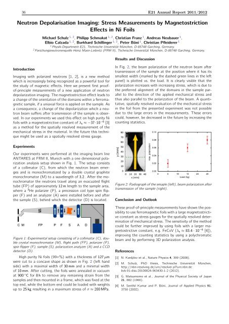
In Fig. 2, the beam polarization of the neutron beam after<br />
transmission of the sample at the position where it has its<br />
smallest width (marked by the dashed green lines in the left<br />
panel) is plotted vs. the load. It is clearly visible that the<br />
polarization increases with increasing stress, which is due to<br />
the preferred alignment of the domains in the sample parallel<br />
to the direction of the applied mechanical stress and<br />
thus also parallel to the polarization of the beam. A quantitative,<br />
spatially resolved evaluation of the mechanical stress<br />
in the foil from the presented experiment was not possible<br />
due to the large errors in the measurements. These errors<br />
could, however, be decreased in the future by increasing the<br />
counting statistics.<br />
Experiments<br />
Our experiments were performed at the imaging beam line<br />
ANTARES at FRM II, Munich with a one dimensional polarization<br />
analysis setup shown in Fig. 1. The setup consists<br />
of a collimator (C), from which the neutron beam emerges<br />
and is monochromatized by a double crystal graphite<br />
monochromator (M) to a wavelength of 3.2 . After the monochromator<br />
the neutrons travel along an evacuated flight<br />
tube (FP) of approximately 12m length to the sample area,<br />
where a 3 He polarizer (P), a precession coil type spin flipper<br />
(F) and an analyzer (A) were installed before and after<br />
the sample (S), behind which the detector (D) is located.<br />
Figure 1: Experimental setup consisting of a collimator (C), double<br />
crystal monochromator (M), flight path (FP), polarizer (P),<br />
spin flipper (F), sample (S), polarization analyzer (A) and a CCD<br />
detector (D).<br />
High purity Ni foils (99+%) with a thickness of 127µm<br />
were cut to a concave shape as shown in Fig. 2 (left hand<br />
side) with a maximal width of 30mm and a minimal width<br />
of 10mm. After cutting, the foils were annealed in vacuum<br />
at 900 ◦ C for 8h to remove any remaining strain from the<br />
samples and then mounted in a frame, which was fixed at the<br />
top end, while the bottom end could be loaded with weights<br />
up to 25kg resulting in a maximum stress of σ ≈ 200MPa.<br />
Figure 2: Radiograph of the smaple (left), beam polarization after<br />
transmission of the sample (right).<br />
Conclusion and Outlook<br />
These proof-of-principle measurements have shown the possibility<br />
to use ferromagnetic foils with a large magnetostrictive<br />
constant as stress gauges for the spatially resolved determination<br />
of mechanical stress. The sensitivity of the method<br />
could be further improved by using foils with a larger magnetostrictive<br />
constant, e.g. FeCoV (λ s ≈ 83.4·10 −6 [4]),<br />
improving the counting statistics by using a polychromatic<br />
beam and by performing 3D polarization analysis.<br />
References<br />
[1] N. Kardjilov et al., Nature Physics 4, 399 (2008).<br />
[2] M. Schulz, PhD thesis, <strong>Technische</strong> Universität München,<br />
http://nbn-resolving.de/urn/resolver.plurn:nbn:de:<br />
bvb:91-diss-20100824-963430-1-2 (<strong>2012</strong>).<br />
[3] G. Matsumomo et al., Journal of the Physical Society of Japan<br />
21, 882 (1966).<br />
[4] M. Senthil Kumar and P. Böni, Journal of Applied Physics 91,<br />
3750 (2002).