
You also want an ePaper? Increase the reach of your titles
YUMPU automatically turns print PDFs into web optimized ePapers that Google loves.
Feb,1999<br />
MC-80<br />
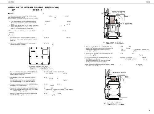
INSTALLING THE INTERNAL ZIP DRIVE UNIT(ZIP-INT-1A) <br />
ZIP ZIP-INT-1A<br />
♦ NOTICE:<br />
<br />
(a)<br />
CN106<br />
CN105<br />
CN103<br />
MC-80 JACK BOARD<br />
CN107<br />
CN110<br />
When the internal hard disk drive unit(HDP-88) has already<br />
been installed in customer’s MC-80,<br />
Remove it before installing the internal ZIP drive unit as follows.<br />
a. Turn off the power for the MC-80 and any connected<br />
devices, and disconnect any cables connected to the<br />
MC-80.<br />
b. Seeing page "INSTALLING THE INTERNAL HARD DISK<br />
DRIVE UNIT(HDP88)", remove the internal hard disk<br />
drive unit from step8 to step2 in reverse steps.<br />
* Return the internal hard disk drive unit with the MC-80 to<br />
customer.<br />
♦ Procedure:<br />
MC-80 (HDP88) <br />
ZIP <br />
<br />
<br />
a. MC-80 MC-80 <br />
<br />
b.HDP88<br />
8 2 <br />
<br />
<br />
MC-80 <br />
<br />
WIRING<br />
IDE-POWER<br />
(c)<br />
(b)<br />
(c)<br />
(d)<br />
CN401<br />
(f)<br />
(f)<br />
CN111<br />
WIRING<br />
IDE<br />
CN402<br />
CN403<br />
(e)<br />
(a)<br />
DD HOLDER<br />
ANGLE HD-R<br />
ANGLE HD-L<br />
(e)<br />
(f)<br />
(f)<br />
(d)<br />
CN108<br />
MC-80 IDE BOARD<br />
(c)<br />
(c)<br />
1. Turn off the power of the MC-80 and the connected<br />
devices, and disconnect all cables that are connected to<br />
the MC-80.<br />
2. Turn the MC-80 over, and remove the bottom cover.<br />
(See fig.1 to remove 12 screws.)<br />
1. MC-80 MC-80 <br />
<br />
2. MC-80 <br />
fig.1 <br />
fig4. before installing the ZIP-INT-1A<br />
fig.1 Bottom Cover View<br />
Remove 12 screws circling in this figure./<br />
8. After securing the ZIP drive to the DD HOLDER with 4<br />
screws, (See fig.5-(g)) connect the WIRING IDE and the<br />
WIRING IDE-POWER to the ZIP drive’s connector<br />
properly.(See fig.5-(h))<br />
9. Secure this DD HOLDER to the boss of a top case with 4<br />
screws. (See fig.5-(i))<br />
10.Connect the WIRING IDE-POWER to the MC-80 JACK<br />
BOARD’s connector(CN103).<br />
And connect the WIRING IDE to the MC-80 JACK<br />
BOARD’s connector(CN111).(See fig.5-(j))<br />
11.After re-sticking a shield sheet to the DD HOLDER, attach<br />
the bottom cover. (See fig.5-(k))<br />
8. DD ZIP <br />
fig.5-(g) <br />
ZIP WIRING IDE WIRING IDE-<br />
POWER fig.5-(h) <br />
9. ZIP DD <br />
fig.5-(i) <br />
10.WIRING IDE-POWER CN103 <br />
WIRING IDE CN111 fig.5-(j) <br />
11. DD HOLDER <br />
fig.5-(k) <br />
3. Remove the WIRING IDE and the WIRING IDE-POWER<br />
from the MC-80 JACK BOARD’s connectors<br />
(CN111,CN103). (See fig.4-(a))<br />
4. After taking off a shield sheet from the DD HOLDER<br />
gently,<br />
(See fig.4-(b)) remove 4 screws connecting the DD<br />
HOLDER and the boss of a top case.(See fig.4-(c))<br />
3. WIRING IDE WIRING IDE-POWER <br />
CN111,CN103 fig.4-(a) <br />
4. DD <br />
fig.4-(b) DD <br />
fig.4-(c) <br />
(j)<br />
WIRING<br />
IDE-POWER<br />
CN106<br />
CN105<br />
CN103<br />
MC-80 JACK BOARD<br />
CN111<br />
(h)<br />
WIRING (j)<br />
IDE<br />
CN107<br />
(h)<br />
CN110<br />
CN108<br />
5. Remove 2 screws connecting the MC-80 IDE BOARD and<br />
the ANGLE HD L/R.(See fig.4-(d))<br />
6. Remove the WIRING IDE and the WIRING IDE-POWER<br />
from the MC-80 IDE BOARD’s connectors(CN401,CN402)<br />
on the DD HOLDER.(See fig.4-(e))<br />
5. IDE HD-L/R <br />
fig.4-(d) <br />
6. DD IDE <br />
WIRING IDE WIRING IDE-POWER CN401,CN402 <br />
fig.4-(e) <br />
(i)<br />
(k)<br />
(g)<br />
DD HOLDER<br />
(g)<br />
(i)<br />
7. Remove 4 screws connecting the DD HOLDER and the<br />
ANGLE HD L/R.(See fig.4-(f))<br />
7. DD HD-L/R <br />
fig.4-(f) <br />
(i)<br />
(g)<br />
(g)<br />
(i)<br />
ZIP-INT-1A<br />
fig5.<br />
after installing the ZIP-INT-1A<br />
25