ZULU T Smart Radio Telemetry Module Smart Radio ... - RF Solutions
ZULU T Smart Radio Telemetry Module Smart Radio ... - RF Solutions
ZULU T Smart Radio Telemetry Module Smart Radio ... - RF Solutions

Create successful ePaper yourself
Turn your PDF publications into a flip-book with our unique Google optimized e-Paper software.
<strong>ZULU</strong> <strong>Telemetry</strong><br />
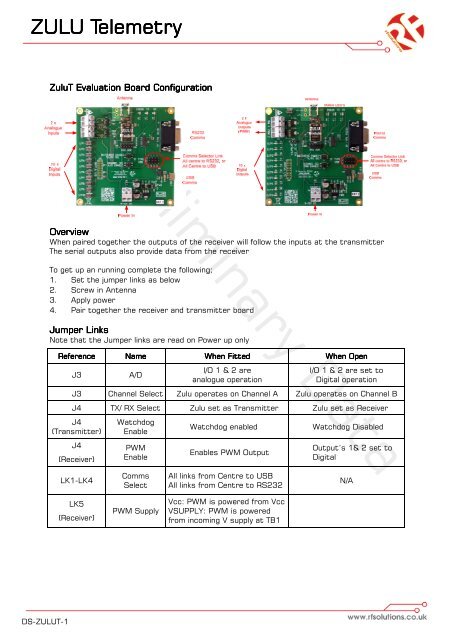
ZuluT Evaluation Board Configuration<br />
Preliminary Data<br />
Overview<br />
When paired together the outputs of the receiver will follow the inputs at the transmitter<br />
The serial outputs also provide data from the receiver<br />
To get up an running complete the following;<br />
1. Set the jumper links as below<br />
2. Screw in Antenna<br />
3. Apply power<br />
4. Pair together the receiver and transmitter board<br />
Jumper Links<br />
Note that the Jumper links are read on Power up only<br />
Reference<br />
J3<br />
Name<br />
A/D<br />
When Fitted<br />
I/O 1 & 2 are<br />
analogue operation<br />
When Open<br />
I/O 1 & 2 are set to<br />
Digital operation<br />
J3 Channel Select Zulu operates on Channel A Zulu operates on Channel B<br />
J4 TX/ RX Select Zulu set as Transmitter Zulu set as Receiver<br />
J4<br />
(Transmitter)<br />
J4<br />
(Receiver)<br />
Watchdog<br />
Enable<br />
PWM<br />
Enable<br />
Watchdog enabled<br />
Enables PWM Output<br />
Watchdog Disabled<br />
Output’s 1& 2 set to<br />
Digital<br />
LK1-LK4<br />
Comms<br />
Select<br />
All links from Centre to USB<br />
All links from Centre to RS232<br />
N/A<br />
LK5<br />
(Receiver)<br />
PWM Supply<br />
Vcc: PWM is powered from Vcc<br />
VSUPPLY: PWM is powered<br />
from incoming V supply at TB1<br />
DS-<strong>ZULU</strong>T-1