Masonry_Chronicles_S.. - Concrete Masonry Association of ...
Masonry_Chronicles_S.. - Concrete Masonry Association of ...
Masonry_Chronicles_S.. - Concrete Masonry Association of ...

Create successful ePaper yourself
Turn your PDF publications into a flip-book with our unique Google optimized e-Paper software.
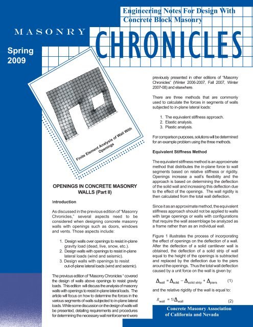
M A S O N R Y<br />
Spring<br />
2009<br />
Engineering Notes For Design With<br />
<strong>Concrete</strong> Block <strong>Masonry</strong><br />
C H R O N I C L E S<br />
previously presented in other editions <strong>of</strong> “<strong>Masonry</strong><br />
<strong>Chronicles</strong>” (Winter 2006-2007, Fall 2007, Winter<br />
2007-08) and elsewhere.<br />
................................<br />
...............................<br />
.............................................................<br />
OPENINGS IN CONCRETE MASONRY<br />
WALLS (Part II)<br />
Introduction<br />
Finite Element Analysis <strong>of</strong> Wall With<br />
Openings<br />
As discussed in the previous edition <strong>of</strong> “<strong>Masonry</strong><br />
<strong>Chronicles</strong>,” several aspects need to be<br />
considered when designing concrete masonry<br />
walls with openings such as doors, windows<br />
and vents. Those aspects include:<br />
1. Design walls over openings to resist in-plane<br />
gravity load (dead, live, snow, etc.).<br />
2. Design walls with openings to resist in-plane<br />
lateral loads (wind and seismic).<br />
3. Design walls with openings to resist<br />
out-<strong>of</strong>-plane lateral loads (wind and seismic).<br />
The previous edition <strong>of</strong> “<strong>Masonry</strong> <strong>Chronicles</strong> “ covered<br />
the design <strong>of</strong> walls above openings to resist gravity<br />
loads. This edition will discuss the analysis <strong>of</strong> masonry<br />
walls with openings to resist in-plane lateral loads. The<br />
article will focus on how to determine the forces in the<br />
various segments <strong>of</strong> walls subjected to in-plane lateral<br />
loads. While some discussion on the design <strong>of</strong> walls will<br />
be presented, detailing requirements and procedures<br />
for determining the necessary wall reinforcement were<br />
1. The equivalent stiffness approach.<br />
2. Elastic analysis.<br />
3. Plastic analysis.<br />
For comparison purposes, solutions will be determined<br />
for an example problem using the three methods.<br />
Equivalent Stiffness Method<br />
The equivalent stiffness method is an approximate<br />
method that distributes the in-plane force to wall<br />
segments based on relative stiffness or rigidity.<br />
Openings increase a wall’s flexibility and the<br />
approach is based on determining the deflection<br />
<strong>of</strong> the solid wall and increasing this deflection due<br />
to the effect <strong>of</strong> the openings. The wall rigidity is<br />
then calculated from the total wall deflection.<br />
Since it as an approximate method, the equivalent<br />
stiffness approach should not be applied to walls<br />
with large openings or walls with configurations<br />
that require the wall assemblage be analyzed as<br />
a frame rather than as an individual wall.<br />
Figure 1 illustrates the process <strong>of</strong> incorporating<br />
the effect <strong>of</strong> openings on the deflection <strong>of</strong> a wall.<br />
After the deflection <strong>of</strong> a solid cantilever wall is<br />
obtained, the deflection <strong>of</strong> a solid strip <strong>of</strong> wall<br />
equal to the height <strong>of</strong> the openings is subtracted<br />
and replaced by the deflection due to the piers<br />
around the openings. Thus the total wall deflection<br />
caused by a unit force on the wall is given by:<br />
wall = _ solid solid strip + piers<br />
(1)<br />
and the relative rigidity <strong>of</strong> the wall is equal to:<br />
R wall<br />
= 1/ wall (2)<br />
<strong>Concrete</strong> <strong>Masonry</strong> <strong>Association</strong><br />
<strong>of</strong> California and Nevada<br />
There are three methods that are commonly<br />
used to calculate the forces in segments <strong>of</strong> walls<br />
subjected to in-plane lateral loads:<br />
Spring 2009 <strong>Chronicles</strong>.indd 1<br />
6/24/2009 10:04:00 AM
Figure 1 – Deflection <strong>of</strong> Wall with Openings<br />
The deflection components are calculated using the<br />
basic strength <strong>of</strong> materials equations for fixed-fixed<br />
piers and fixed-free piers, depending on the boundary<br />
conditions, as shown in Figure 2. The deflections <strong>of</strong><br />
the solid strip and pier are typically obtained assuming<br />
a fixed-fixed condition, since there is usually sufficient<br />
amount <strong>of</strong> wall above the openings to restrain rotation<br />
at the top <strong>of</strong> the piers.<br />
deformation and the second term is the shear<br />
deformation. The bending term considers the wall as<br />
a simple vertical cantilever beam with a moment <strong>of</strong><br />
inertia, I, which includes returns or pilasters at the<br />
ends <strong>of</strong> the wall. The cross-sectional area, A, is the<br />
area <strong>of</strong> the web and omits the flange areas. E m and E v<br />
are the Young’s modulus and shear modulus,<br />
respectively, which are given in Section 1.8.2.2 <strong>of</strong> ACI<br />
530-05/ASCE 5-05/TMS402-05 [1], also referred to as<br />
the 2005 <strong>Masonry</strong> Standards Joint Committee Building<br />
Code (MSJC), as:<br />
E = 900 f '<br />
(4)<br />
m<br />
m<br />
E = 0.4E (5)<br />
v<br />
m<br />
where f’ m is the masonry compressive strength.<br />
Assuming a unit lateral load that causes a deflection <strong>of</strong><br />
Δ is applied, Equations (3) and (5) can be used to<br />
obtain:<br />
3<br />
⎛H<br />
⎞ ⎛3H<br />
⎞<br />
Em<br />
Δ= ⎜ ⎟+<br />
⎜ ⎟<br />
(6)<br />
⎝ 3I<br />
⎠ ⎝ A ⎠<br />
Figure 2 – Deformation <strong>of</strong> Walls and Piers<br />
For fixed-free wall segments, the deflection is equal to:<br />
3<br />
VH 1.2VH<br />
Δ= +<br />
3E I AE<br />
m<br />
v<br />
where H is the height <strong>of</strong> the wall or pier and L is the<br />
length. The first term represents bending or flexural<br />
(3)<br />
For walls with rectangular cross-sections (no flanges)<br />
the cross-sectional area and moment <strong>of</strong> inertia are<br />
equal to:<br />
A = tL (7)<br />
3<br />
I = tL<br />
(8)<br />
12
Therefore, Equation (6) can be further simplified to:<br />
⎛H<br />
⎞ ⎛H<br />
⎞<br />
tEm<br />
Δ= 4⎜ ⎟ + 3⎜ ⎟<br />
⎝ L ⎠ ⎝ L ⎠<br />
3<br />
It is important to note that when determining the<br />
distribution <strong>of</strong> earthquake loads, it is the relative rigidity<br />
<strong>of</strong> the walls that is required. Therefore, for walls with<br />
the same thickness the leading terms in Equation (9)<br />
can be ignored and the relative rigidity <strong>of</strong> each pier or<br />
wall segment is equal to:<br />
R<br />
1 1<br />
Δ ⎛ H ⎞ ⎛ H ⎞<br />
⎢4⎜ ⎟ + 3⎜ ⎟⎥<br />
⎢⎣<br />
⎝ L ⎠ ⎝ L ⎠⎥⎦<br />
= =<br />
⎡<br />
3 ⎤<br />
(10)<br />
The tops <strong>of</strong> masonry shear walls or piers are<br />
sometimes restrained by deep beams so that the<br />
deformation occurs with no rotation at the top <strong>of</strong> the<br />
wall, as shown in Figure 2(b). In order to obtain the<br />
deformed shape shown in Figure 2(b) the restraining<br />
beam must possess both the stiffness and strength to<br />
resist the moment that develops at the top <strong>of</strong> the wall.<br />
From beam theory, the deflection <strong>of</strong> a wall or pier that<br />
is prevented from rotating at the top is equal to:<br />
3<br />
VH 1.2VH<br />
Δ= +<br />
12E I AE<br />
m<br />
v<br />
(11)<br />
(9)<br />
If the openings are at different elevations, this method<br />
becomes more complex as can be seen in the<br />
examples. It should be noted the procedure described<br />
above for obtaining the distribution <strong>of</strong> earthquake<br />
loads to shear walls is an approximate method at best.<br />
Calculations are based on elastic, uncracked masonry<br />
wall cross-sections. While it may be justifiable to use<br />
uncracked section properties for extremely low levels<br />
<strong>of</strong> loading, actual response <strong>of</strong> buildings during design<br />
level earthquakes will be extremely nonlinear and<br />
result in cracking <strong>of</strong> the masonry shear walls.<br />
Determining the stiffness <strong>of</strong> cracked reinforced<br />
masonry shear walls can be quite complex and the<br />
stiffness <strong>of</strong> a cracked masonry wall varies significantly<br />
depending on the degree <strong>of</strong> cracking. Thus, it is<br />
important to emphasize that the relative rigidity only<br />
provides an estimate <strong>of</strong> the distribution <strong>of</strong> earthquake<br />
loads and that the true distribution will not be<br />
completely predictable during a major earthquake.<br />
Nevertheless, a good design that utilizes walls <strong>of</strong><br />
similar rigidity that are placed in a symmetrical pattern<br />
will have a more predictable seismic response<br />
behavior, even with the significant cracking expected<br />
during major earthquakes.<br />
Example 1<br />
Determine the distribution <strong>of</strong> the forces in the shear<br />
walls shown in Figure 3 using the equivalent stiffness<br />
approach. A 30 kip lateral force is applied at the top <strong>of</strong><br />
the walls and a drag strut distributes the force to the<br />
two walls.<br />
Noting that E v = 0.4E m and substituting Equations (7)<br />
and (8) for the wall area and moment <strong>of</strong> inertia:<br />
3<br />
⎡ ⎤⎛ ⎞<br />
⎛H ⎞ ⎛H ⎞ V<br />
Δ = ⎢⎜ ⎟ + 3⎜ ⎟⎥⎜<br />
⎣⎢⎝ L ⎠ ⎝ L ⎠⎦⎥⎝tE ⎟ (12)<br />
m ⎠<br />
Neglecting the common terms, the relative rigidity <strong>of</strong><br />
“fixed-fixed” walls or piers is given by:<br />
R<br />
1 1<br />
Δ ⎛ H ⎞ ⎛ H ⎞<br />
⎢⎜ ⎟ + 3⎜ ⎟⎥<br />
⎢⎣⎝ L ⎠ ⎝ L ⎠⎥⎦<br />
= =<br />
⎡<br />
3 ⎤<br />
(13)<br />
Once the stiffness <strong>of</strong> each pier or wall segment is<br />
determined, the lateral force to the wall will be<br />
distributed to individual elements based on the relative<br />
rigidity:<br />
Figure 3 – Example Walls<br />
Solution:<br />
Determine the relative rigidity <strong>of</strong> Wall 1(fixed-free):<br />
⎛ H ⎞ ⎛ H ⎞<br />
Δ<br />
1<br />
= 4⎜ ⎟ + 3⎜ ⎟<br />
⎝ L ⎠ ⎝ L ⎠<br />
3<br />
V<br />
i<br />
=<br />
Ri<br />
V<br />
R<br />
n<br />
∑<br />
i=1<br />
i<br />
(14)<br />
3<br />
⎛16 ⎞ ⎛16<br />
⎞<br />
= 4⎜ ⎟ + 3⎜ ⎟=<br />
38.0<br />
⎝ 8 ⎠ ⎝ 8 ⎠<br />
1 1<br />
R1<br />
= = = 0.026<br />
Δ 38.0
Determine the relative rigidity <strong>of</strong> Wall 2 (fixed-free):<br />
3<br />
⎛16 ⎞ ⎛16<br />
⎞<br />
Δ<br />
Solid<br />
= 4⎜ ⎟ + 3⎜ ⎟=<br />
5.476<br />
wall ⎝18 ⎠ ⎝18<br />
⎠<br />
For the solid strip that contains piers 3, 4, 5 and 6<br />
(fixed-fixed):<br />
3<br />
⎛ 8 ⎞ ⎛ 8 ⎞<br />
Δ<br />
Solid<br />
= ⎜ ⎟ + 3⎜ ⎟=<br />
1.421<br />
Strip ⎝18 ⎠ ⎝18<br />
⎠<br />
For pier 3:<br />
3<br />
⎛8⎞ ⎛8⎞<br />
Δ<br />
3<br />
= ⎜ ⎟ + 3⎜ ⎟=<br />
14.0;<br />
⎝4⎠ ⎝4⎠<br />
1<br />
R3<br />
= = 0.071<br />
14<br />
For the solid strip that contains piers 4, 5 and 6:<br />
Similarly, for piers 3, 4, 5 and 6:<br />
1 1<br />
Δ<br />
piers<br />
= = = 3.559<br />
1 1 1 1<br />
+ +<br />
Δ Δ 14.0 4.763<br />
3 456<br />
and for the entire wall:<br />
Δ =Δ −Δ +Δ<br />
2<br />
solid solid piers<br />
wall strip<br />
= 5.476 − 1.421+ 3.559 = 7.614<br />
1 1<br />
R2<br />
= = = 0.131<br />
Δ 7.614<br />
2<br />
The forces in each wall pier can then be calculated as<br />
follows:<br />
F<br />
R<br />
1<br />
1<br />
= ×<br />
R1 + R2<br />
30<br />
3<br />
⎛ 8 ⎞ ⎛ 8 ⎞<br />
Δ<br />
solid<br />
= ⎜ ⎟ + 3⎜ ⎟=<br />
2.912<br />
456 ⎝10 ⎠ ⎝10<br />
⎠<br />
and for piers 4 and 5:<br />
3<br />
⎛ 4 ⎞ ⎛ 4 ⎞<br />
Δ<br />
solid<br />
= ⎜ ⎟ + 3⎜ ⎟=<br />
1.264<br />
strip ⎝10 ⎠ ⎝10<br />
⎠<br />
3<br />
⎛4⎞ ⎛4⎞<br />
1<br />
Δ<br />
4<br />
= ⎜ ⎟ + 3⎜ ⎟= 4.0; R4<br />
= = 0.25<br />
⎝4⎠ ⎝4⎠<br />
4.0<br />
3<br />
⎛4⎞ ⎛4⎞<br />
1<br />
Δ<br />
5<br />
= ⎜ ⎟ + 3⎜ ⎟= 14.0; R5<br />
= = 0.071<br />
⎝2 ⎠ ⎝2 ⎠<br />
14.0<br />
1 1<br />
Δ<br />
piers<br />
= = = 3.115<br />
1 1 1 1<br />
+ +<br />
Δ Δ 4.0 14.0<br />
4 5<br />
0.026<br />
= × 30 = 4.97 kips<br />
0.026 + 0.131<br />
F<br />
F<br />
R<br />
2<br />
2<br />
= ×<br />
R1 + R2<br />
30<br />
0.131<br />
= × 30 = 25.03 kips<br />
0.026 + 0.131<br />
R<br />
3<br />
3<br />
= ×<br />
R3 + R456<br />
25.03<br />
0.071<br />
= × 25.03 = 6.32 kips<br />
0.21+<br />
0.071<br />
F4 − 5 − 6= 25.03 − 6.32 = 18.71 kips<br />
Therefore the total deflection <strong>of</strong> piers 4, 5 and 6 is<br />
equal to: R4<br />
F4<br />
= × 18.71<br />
R4 + R5<br />
Δ =Δ −Δ +Δ<br />
456<br />
solid strip piers<br />
456<br />
= 2.912 − 1.264 + 3.115 = 4.763<br />
0.25<br />
= × 18.71 = 14.57 kips<br />
0.25 + 0.071<br />
R<br />
456<br />
1<br />
= =0.21<br />
Δ<br />
F<br />
5<br />
= 18.71− 14.57 = 4.14 kips
Figure 4 – Solution to Example 1<br />
Elastic Analysis<br />
An elastic analysis <strong>of</strong> walls with openings can be<br />
performed to determine the forces in each <strong>of</strong> the wall<br />
segments. This typically involves the use <strong>of</strong> a finite<br />
element analysis program that can model a wall with<br />
membrane or shell elements in order to adequately<br />
capture the behavior <strong>of</strong> the wall and the effect <strong>of</strong><br />
openings. The finite element grid must be fine<br />
enough to capture the flexural and shear<br />
deformation components <strong>of</strong> deflection.<br />
Example 2<br />
Determine the distribution <strong>of</strong> the forces in the shear<br />
walls shown in Figure 3 using the elastic analysis.<br />
Solution:<br />
The walls shown in Figure 3 were modeled using the<br />
computer program SAP 2000 ® [2]. The computer<br />
model is shown in Figure 5 and the deformed shape<br />
due to the lateral load is shown in Figure 6. Figure 7<br />
shows the forces in the various wall segments that<br />
resulted from the computer analysis.<br />
Figure 7 – Solution to Example 2<br />
Comparisons <strong>of</strong> Figures 4 and 7 indicate that there<br />
are significant differences in the results obtained<br />
from the equivalent stiffness method and the<br />
computer analysis. The differences are highlighted<br />
by the shear force in Wall 1, which increases by<br />
about 27% when a finite element analysis is<br />
performed. In addition, the equivalent stiffness<br />
approach does not provide information on the axial<br />
loads that occur in the walls segments due to the<br />
overturning effect <strong>of</strong> the lateral load.<br />
A primary reason for the difference in results is the<br />
assumption that wall segments are either perfectly<br />
“fixed-fixed” or “fixed-free” when using the equivalent<br />
stiffness approach. In reality, the boundary<br />
conditions at the ends <strong>of</strong> wall segments may be<br />
significantly different from these idealized<br />
assumptions, and the coupling effect <strong>of</strong> the<br />
horizontal wall segments results in axial loads that<br />
depend on the relative stiffness. This <strong>of</strong>ten results in<br />
an overestimation <strong>of</strong> the stiffness <strong>of</strong> walls with<br />
openings. Computer models allow the designer to<br />
incorporate the rotation at the ends <strong>of</strong> piers and the<br />
coupling effect <strong>of</strong> horizontal wall segments.<br />
Figure 5 – Finite Element Model for Example 2<br />
Figure 6 – Deformed Shape <strong>of</strong> Walls<br />
Plastic Analysis<br />
The elastic analysis computer analysis clearly<br />
provides better results than the equivalent stiffness<br />
method. However, since response during large<br />
earthquakes occurs in the nonlinear range <strong>of</strong><br />
structural response, an elastic analysis is still an<br />
approximation and may not always represent the<br />
true nonlinear response <strong>of</strong> a concrete masonry wall<br />
with openings.<br />
Plastic analysis <strong>of</strong> masonry walls has been<br />
suggested in various forms, for several years [3, 4].<br />
Terms such as limit analysis, limit state design and<br />
displacement analysis are also <strong>of</strong>ten used to<br />
describe the procedure. A primary advantage <strong>of</strong><br />
plastic or limit state analysis is the engineer’s ability<br />
to dictate building performance during seismic<br />
events without extensive analysis. The engineer<br />
selects a plastic mechanism that defines the wall<br />
behavior and then verifies that the various wall
segments have sufficient ductility to incur<br />
deformation demands that correspond to the<br />
selected mechanism. This typically involves design<br />
to avoid brittle failure modes such as shear failures,<br />
and a verification that the compressive strains are<br />
within acceptable limits at the maximum<br />
displacement.<br />
Note that since Wall 1 is not attached to the<br />
remainder <strong>of</strong> the assembly by a coupling beam, it<br />
does not experience any axial load. Wall segment 2<br />
acts as a coupling beam between the piers and<br />
induces axial loads in addition to the shear and<br />
flexural forces on the piers.<br />
This article only addresses some basic aspects <strong>of</strong><br />
plastic design <strong>of</strong> masonry walls as a detailed<br />
discussion <strong>of</strong> the method and different approaches<br />
would require a more extensive discussion. The<br />
<strong>Masonry</strong> Standards Joint Committee is currently<br />
working on developing standardized procedures for<br />
performing plastic design on masonry walls.<br />
Example 3<br />
Determine the distribution <strong>of</strong> the forces in the shear<br />
walls shown in Figure 3 using the plastic analysis.<br />
Solution:<br />
The first step is the determination <strong>of</strong> a mechanism<br />
for the wall. While mechanisms with plastic hinges<br />
in the beams are preferred, this is not always<br />
possible when the configuration <strong>of</strong> openings results<br />
in deep beams and narrow piers. Figure 8 shows<br />
the selected mechanism for the example problem.<br />
As can be seen, pier mechanisms with plastic<br />
hinges in the piers can <strong>of</strong>ten create large<br />
deformation demands in the piers.<br />
Figure 9 – Solution to Example 3<br />
It should be noted that while the plastic mechanism<br />
defines the loads on each plastic hinge at the<br />
maximum wall displacement (ultimate limit state),<br />
each hinge does not occur at the same time. This<br />
means that the inelastic demands on some wall<br />
segments may be significantly different from others.<br />
To ensure that the wall has adequate ductility, the<br />
deformation capacity <strong>of</strong> each pier and walls segment<br />
must be verified.<br />
A simplified approach is to conservatively ignore the<br />
elastic deformation <strong>of</strong> the wall and assume that all<br />
displacement is as a result <strong>of</strong> plastic rotation. Then<br />
the plastic rotation demand, θ pu, is given by:<br />
θ<br />
pu<br />
Δ<br />
u<br />
( H′ − 0.5Hp<br />
)<br />
(15)<br />
Figure 8 – Plastic Mechanism for Example 3<br />
The next step is the distribution <strong>of</strong> wall loads to the<br />
wall segments. Theoretically, any distribution <strong>of</strong><br />
forces that satisfies equilibrium and is compatible<br />
with the selected mechanism may be used.<br />
However, it is best to distribute the loads by taking<br />
into consideration the potential force and<br />
deformation capacity <strong>of</strong> the various wall segments.<br />
For this example, the total shear force is distributed<br />
to the piers and walls segments in proportion to their<br />
lengths. The resulting forces are shown in Figure 9.<br />
where H’ is height <strong>of</strong> the equivalent cantilever (half<br />
the height <strong>of</strong> piers subjected to double curvature)<br />
and H p is the plastic hinge length, which is usually<br />
taken as half the length <strong>of</strong> the wall segment. Δ u is<br />
the maximum displacement <strong>of</strong> the wall calculated<br />
from the analysis <strong>of</strong> the structure. The plastic<br />
rotation capacity is based on the maximum usable<br />
compressive strain in the masonry:<br />
ε<br />
θ = mu<br />
pn<br />
c<br />
H<br />
p<br />
(16)<br />
where the maximum usable compressive strain, E mu ,<br />
is equal to 0.0025 for concrete masonry and c is the<br />
depth <strong>of</strong> the neutral axis corresponding to the<br />
maximum usable compressive strain.
Design and Detailing <strong>of</strong> Walls with Openings<br />
Irrespective <strong>of</strong> the method used to determine the<br />
forces in the walls, piers and wall segments, the<br />
walls must be designed to satisfy the requirements<br />
<strong>of</strong> the International Building Code (IBC) [5] and the<br />
MSJC code [1]. Gravity loads must be combined<br />
with lateral loads using the appropriate load<br />
combinations.<br />
Section 3.1.3.1 <strong>of</strong> the MSJC code states that at each<br />
story level and line <strong>of</strong> resistance <strong>of</strong> buildings assigned<br />
to seismic design category C and greater, at least 80<br />
percent <strong>of</strong> the lateral stiffness must be provided by<br />
lateral-force-resisting walls. Piers and columns may<br />
be used to provide earthquake load resistance if a<br />
response modification factor, R, <strong>of</strong> no greater than 1.5<br />
is used to calculate earthquake loads.<br />
One interpretation <strong>of</strong> this stipulation is that if all piers<br />
satisfy the design and detailing requirements for<br />
shear walls required in a seismic design category,<br />
the values <strong>of</strong> R for shear walls may be used (i.e. 3.5<br />
for intermediate reinforced masonry shear walls and<br />
5 for special reinforced shear walls in bearing wall<br />
systems). This means that in addition to other<br />
detailing requirements, the piers must satisfy the<br />
requirements for minimum and maximum<br />
reinforcement, reinforcement spacing and the<br />
amplified shear demands on walls in seismic<br />
regions. This will ensure that the wall segments<br />
possess sufficient ductility to justify a use <strong>of</strong> the<br />
selected response modification factor. It is<br />
recommended that strength design procedures are<br />
used to design masonry shear walls with openings<br />
since this provides a more accurate determination <strong>of</strong><br />
the capacity <strong>of</strong> wall segments subjected to<br />
earthquake loading.<br />
If the wall design and detailing requirements cannot<br />
be satisfied, and this is <strong>of</strong>ten the case with walls that<br />
have short squat piers, a response modification<br />
factor <strong>of</strong> 1.5 should be used and the wall must<br />
satisfy the less stringent pier detailing requirements,<br />
some <strong>of</strong> which are as follows (MSJC Section<br />
3.3.4.3):<br />
a. One bar shall be provided in the end cells.<br />
b. Minimum area <strong>of</strong> longitudinal reinforcement shall<br />
Be 0.0007bd.<br />
c. Longitudinal reinforcement shall be uniformly<br />
Distributed throughout the depth <strong>of</strong> the element.<br />
Conclusions<br />
Various methods have been presented for analyzing<br />
concrete masonry with openings that are subjected<br />
to in-plane lateral loads. The equivalent stiffness<br />
approach, while easily performed with hand<br />
calculations, is extremely approximate and can <strong>of</strong>ten<br />
lead to non-conservative designs. The equivalent<br />
stiffness approach also does not provide information<br />
on the axial loads resulting from the coupling effect<br />
<strong>of</strong> beams in walls. This is a significant shortcoming<br />
since the strength and deformation capacity <strong>of</strong><br />
concrete masonry elements is <strong>of</strong>ten highly<br />
dependent on axial load.<br />
Elastic analysis with computer programs overcome<br />
several <strong>of</strong> the limitations <strong>of</strong> the equivalent stiffness<br />
approach and assist in the design <strong>of</strong> safe,<br />
earthquake resistant structures. Plastic analysis can<br />
provide the engineer with the ability to control the<br />
earthquake response <strong>of</strong> walls using capacity design<br />
procedures. Standardized procedures for plastic<br />
design <strong>of</strong> masonry walls are currently being<br />
developed.<br />
References<br />
[1] <strong>Masonry</strong> Standards Joint Committee (MSJC),<br />
Building Code Requirements for <strong>Masonry</strong> Structures,<br />
<strong>Masonry</strong> Standards Joint Committee, Boulder,<br />
Colorado, 2005.<br />
[2] Computers and Structures, Inc, SAP 2000 User’s<br />
Manual, Berkeley California, 2008.<br />
[3] Leiva, G., and Klingner, R., Technical<br />
Coordinating Committee for <strong>Masonry</strong> Research<br />
(TCCMaR) Report No. 3.1(c)-2: In-plane Seismic<br />
Resistance <strong>of</strong> Two-story <strong>Concrete</strong> <strong>Masonry</strong> Shear<br />
Walls with Openings, 1991.<br />
[4] Drysdale, R. G., Hamid, A. A., <strong>Masonry</strong><br />
Structures: Behavior and Design, 3rd edition, The<br />
<strong>Masonry</strong> Society, Boulder, CO 2005.<br />
[5] International Code Council (ICC), 2006<br />
International Building Code, International Code<br />
Council, Inc., Falls Church, Virginia, 2006.<br />
This edition <strong>of</strong> <strong>Masonry</strong> <strong>Chronicles</strong> was written by<br />
Chukwuma Ekwueme, PhD., S.E., and Henry Huang<br />
P.E., LEED AP <strong>of</strong> Weidlinger Associates, Inc.,<br />
Marina Del Rey, California.
<strong>Concrete</strong> <strong>Masonry</strong> <strong>Association</strong><br />
<strong>of</strong> California and Nevada<br />
6060 Sunrise Vista Drive, Suite 1990<br />
Citrus Heights, CA 95610<br />
(916) 722-1700<br />
Info@cmacn.org<br />
www.cmacn.org<br />
Presort<br />
Standard<br />
U.S. Postage<br />
PAID<br />
Premit No. 604<br />
Sacramento, CA<br />
CHANGE SERVICE REQUESTED<br />
<strong>Concrete</strong> <strong>Masonry</strong> is<br />
Safe & Sound.<br />
www.cmacn.org<br />
Contact CMACN with Requests for Design Seminars at (916) 722-1700 or info@cmacn.org<br />
Now Available: 2006 Design <strong>of</strong> Reinforced <strong>Masonry</strong> Structures, CMD06 Computer<br />
Program, Typical <strong>Masonry</strong> Details CD includes AutoCAD and PDF formats<br />
<strong>Concrete</strong> <strong>Masonry</strong> <strong>Association</strong> <strong>of</strong> California and Nevada (CMACN) is pleased to introduce updated products for<br />
practicing engineers.<br />
Orders can be placed on line at www.cmacn.org (all cards accepted) or by calling (916) 722-1700 (Visa and MasterCard only).<br />
CMACN PRODUCER MEMBERS<br />
Producer Members are an individual, partnership, or corporation, which is actively engaged in the manufacture<br />
and sale <strong>of</strong> concrete masonry units.<br />
Air Vol Block, Inc.<br />
Angelus Block Company, Inc.<br />
Basalite <strong>Concrete</strong> Products, LLC<br />
Blocklite (a subsidiary <strong>of</strong> Basalite <strong>Concrete</strong> Products LLC)<br />
Calstone Company, Inc.<br />
Castlelite Block LLC<br />
Cind-R-Lite Block Company, Inc.<br />
Desert Block Company, Inc.<br />
Oldcastle APG West, Inc.<br />
ORCO Block Company, Inc.<br />
RCP Block & Brick, Inc.<br />
Tri Delta (a division <strong>of</strong> Oldcastle APG West, Inc.)<br />
Spring 2009 <strong>Chronicles</strong>.indd 2<br />
6/24/2009 10:05:15 AM