maintenance kit instructions hp laserjet 4000, 4050, 4100 - Lbrty.com
maintenance kit instructions hp laserjet 4000, 4050, 4100 - Lbrty.com
maintenance kit instructions hp laserjet 4000, 4050, 4100 - Lbrty.com

You also want an ePaper? Increase the reach of your titles
YUMPU automatically turns print PDFs into web optimized ePapers that Google loves.
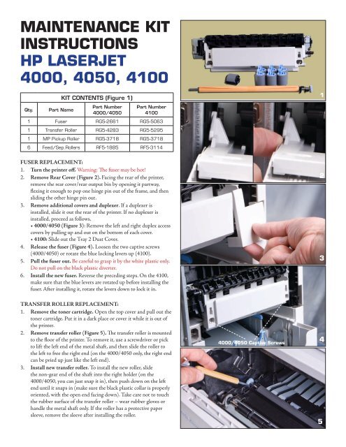
MAINTENANCE KIT<br />
INSTRUCTIONS<br />
HP LASERJET<br />
<strong>4000</strong>, <strong>4050</strong>, <strong>4100</strong><br />
Qty. Part Name<br />
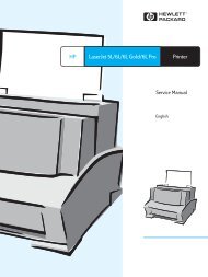
KIT CONTENTS (Figure 1)<br />
Part Number<br />
<strong>4000</strong>/<strong>4050</strong><br />
Part Number<br />
<strong>4100</strong><br />
1 Fuser RG5-2661 RG5-5063<br />
1 Transfer Roller RG5-4283 RG5-5295<br />
1 MP Pickup Roller RG5-3718 RG5-3718<br />
6 Feed/Sep.Rollers RF5-1885 RF5-3114<br />
FUSER REPLACEMENT:<br />
1. Turn the printer off. Warning: The fuser may be hot!<br />
2. Remove Rear Cover (Figure 2). Facing the rear of the printer,<br />
remove the rear cover/rear output bin by opening it partway,<br />
flexing it enough to pop one hinge pin out of the frame, and then<br />
sliding the other hinge pin out.<br />
3. Remove additional covers and duplexer. If a duplexer is<br />
installed, slide it out the rear of the printer. If no duplexer is<br />
installed, proceed as follows.<br />
• <strong>4000</strong>/<strong>4050</strong> (Figure 3): Remove the left and right duplex access<br />
covers by pulling up and out on the bottom of each cover.<br />
• <strong>4100</strong>: Slide out the Tray 2 Dust Cover.<br />
4. Release the fuser (Figure 4). Loosen the two captive screws<br />
(<strong>4000</strong>/<strong>4050</strong>) or rotate the blue locking levers up (<strong>4100</strong>).<br />
5. Pull the fuser out. Be careful to grasp it by the white plastic only.<br />
Do not pull on the black plastic diverter.<br />
6. Install the new fuser. Reverse the preceding steps. On the <strong>4100</strong>,<br />
make sure that the blue levers are rotated up before installing the<br />
fuser. After installing it, rotate the levers down to lock it in.<br />
TRANSFER ROLLER REPLACEMENT:<br />
1. Remove the toner cartridge. Open the top cover and pull out the<br />
toner cartridge. Put it in a dark place or cover it while it is out of<br />
the printer.<br />
2. Remove transfer roller (Figure 5). The transfer roller is mounted<br />
to the floor of the printer. To remove it, use a screwdriver or pick<br />
to lift the left end of the metal shaft, and then slide the roller to<br />
the left to free the right end (on the <strong>4000</strong>/<strong>4050</strong> only, the right end<br />
can be pried up just like the left end).<br />
3. Install new transfer roller. To install the new roller, slide<br />
the non-gear end of the shaft into the right holder (on the<br />
<strong>4000</strong>/<strong>4050</strong>, you can just snap it in), then push down on the left<br />
end until it snaps in (make sure the black plastic collar is properly<br />
oriented, with the open end facing down). Take care not to touch<br />
the rubber surface of the transfer roller – wear rubber gloves or<br />
handle the metal shaft only. If the roller has a protective paper<br />
sleeve, remove the sleeve after installing the roller.<br />
<strong>4000</strong>/<strong>4050</strong> Captive Screws<br />
1<br />
2<br />
3<br />
4<br />
5
Maintenance Kit <strong>instructions</strong><br />
HP LJ <strong>4000</strong>, <strong>4050</strong>, <strong>4100</strong>,<br />
continued<br />
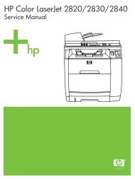
MP PICKUP ROLLER REPLACEMENT:<br />
1. Remove Envelope Entrance Cover. Open the MP tray and locate<br />
the roller. Remove the plastic envelope entrance cover (directly<br />
above the roller) by pulling it toward you. (Figure 6).<br />
2. Remove Roller. Pry open the blue latch on the roller (Figure 7),<br />
and then lift the roller out.<br />
3. Install New Roller. Make sure that the pin on the underside of<br />
the roller lines up with the hole in the shaft (Figure 8). Secure the<br />
roller by closing the blue latch.<br />
4. Replace the envelope entrance cover and close the MP tray.<br />
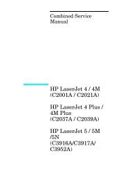
SEPARATION ROLLER REPLACEMENT (Figure 9):<br />
1. Remove Paper Cassette. It may also help to remove all paper<br />
from the cassette. The separation roller is in the front of the<br />
cassette.<br />
2. Remove Access Cover. Release the latch and lift the access cover<br />
to the left of the roller.<br />
3. Remove Roller. Pinch the blue clip and slide the roller off to the<br />
left.<br />
4. Install New Roller. When installing the new roller, make sure it<br />
locks into place. Also make sure to close and latch the access cover.<br />
5. Repeat Steps 1-4 for any additional cassettes.<br />
FEED ROLLER REPLACEMENT (Figure 10):<br />
1. Locate and Remove Roller. The feed roller is mounted to the<br />
feeder frame directly above the separation roller. To access it,<br />
remove the paper cassette from the printer. The feed roller is<br />
identical to the separation roller, and is replaced the same way<br />
(except that there is no access cover).<br />
2. Repeat Step 1 for any additional cassettes.<br />
RESETTING THE MAINTENANCE MESSAGE/COUNT:<br />
1. Turn the printer off. Then press and hold the left (“-“) side of<br />
both the Item and Value keys while powering on. Continue<br />
holding these keys until the display reads “Reset Maintenance<br />
Count” (on some printers, it will read “Count”), then release them.<br />
Once the display goes to “Ready,” print a configuration page and<br />
check that “Pages Since Last Maintenance” has gone to zero. If<br />
not, go to Step 2.<br />
2. On some printers (most notably, the LaserJet <strong>4000</strong> when a<br />
<strong>maintenance</strong> <strong>kit</strong> is installed prematurely – before the “Perform<br />
User Maintenance” message <strong>com</strong>es up), Step 1 will not work. In<br />
these cases, you will have to go into service mode and directly<br />
manipulate the <strong>maintenance</strong> count:<br />
a. Turn the printer off. Then press and hold Select and Cancel Job<br />
while powering on. Continue to hold these keys until all display<br />
lights are on, then release them.<br />
b. Press and release the right side of Menu, then Select. The<br />
display will briefly show “Service Mode” and return to this after<br />
initializing.<br />
c. Go into the Service Menu and set “Maintenance Count” to zero,<br />
one digit at a time (Value changes the underlined digit; Select<br />
6<br />
Pin Hole<br />
Roller Clip<br />
Access Cover Latch<br />
Roller Clip<br />
7<br />
8<br />
9<br />
10<br />
sets that digit and moves to the next one – make sure to select<br />
all digits). When finished, press Go twice to exit the service<br />
mode. Caution: Do not change the “Maintenance Interval” – in<br />
particular, do not set it to zero! This can cause a permanent<br />
“49” error and necessitate replacement of the formatter board.<br />
d. Print a configuration page. One of two things will happen:<br />
(1) “Pages Since Last Maintenance” will have gone to zero (in<br />
this case, no further action is required);<br />
(2) “Perform User Maintenance” will <strong>com</strong>e up on the display. In<br />
this case, go back and perform Step 1, which will now work.