Suburban Furnace Service Manual - BR Wholesale RV & Marine
Suburban Furnace Service Manual - BR Wholesale RV & Marine
Suburban Furnace Service Manual - BR Wholesale RV & Marine

Create successful ePaper yourself
Turn your PDF publications into a flip-book with our unique Google optimized e-Paper software.
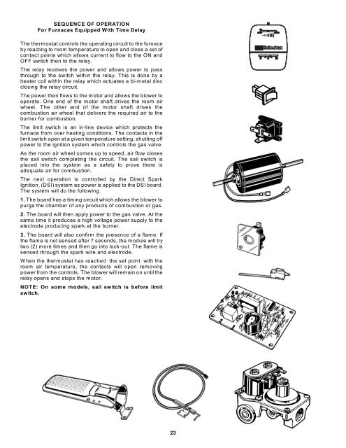
SEQUENCE OF OPERATION<br />
For <strong>Furnace</strong>s Equipped With Time Delay<br />
The thermostat controls the operating circuit to the furnace<br />
by reacting to room temperature to open and close a set of<br />
contact points which allows current to flow to the ON and<br />
OFF switch then to the relay.<br />
The relay receives the power and allows power to pass<br />
through to the switch within the relay. This is done by a<br />
heater coil within the relay which actuates a bi-metal disc<br />
closing the relay circuit.<br />
The power then flows to the motor and allows the blower to<br />
operate. One end of the motor shaft drives the room air<br />
wheel. The other end of the motor shaft drives the<br />
combustion air wheel that delivers the required air to the<br />
burner for combustion.<br />
The limit switch is an in-line device which protects the<br />
furnace from over heating conditions. The contacts in the<br />
limit switch open at a given temperature setting, shutting off<br />
power to the ignition system which controls the gas valve.<br />
As the room air wheel comes up to speed, air flow closes<br />
the sail switch completing the circuit. The sail switch is<br />
placed into the system as a safety to prove there is<br />
adequate air for combustion.<br />
The next operation is controlled by the Direct Spark<br />
Ignition, (DSI) system as power is applied to the DSI board.<br />
The system will do the following.<br />
1. The board has a timing circuit which allows the blower to<br />
purge the chamber of any products of combustion or gas.<br />
2. The board will then apply power to the gas valve. At the<br />
same time it produces a high voltage power supply to the<br />
electrode producing spark at the burner.<br />
3. The board will also confirm the presence of a flame. If<br />
the flame is not sensed after 7 seconds, the module will try<br />
two (2) more times and then go into lock-out. The flame is<br />
sensed through the spark wire and electrode.<br />
When the thermostat has reached the set point with the<br />
room air temperature, the contacts will open removing<br />
power from the controls. The blower will remain on until the<br />
relay opens and stops the motor.<br />
NOTE: On some models, sail switch is before limit<br />
switch.<br />
23