Suburban Furnace Service Manual - BR Wholesale RV & Marine
Suburban Furnace Service Manual - BR Wholesale RV & Marine
Suburban Furnace Service Manual - BR Wholesale RV & Marine

Create successful ePaper yourself
Turn your PDF publications into a flip-book with our unique Google optimized e-Paper software.
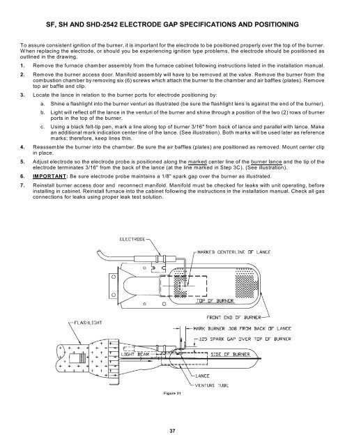
SF, SH AND SHD-2542 ELECTRODE GAP SPECIFICATIONS AND POSITIONING<br />
To assure consistent ignition of the burner, it is important for the electrode to be positioned properly over the top of the burner.<br />
W hen replacing the electrode, or should you be experiencing ignition type problems, the electrode should be positioned as<br />
outlined in the drawing.<br />
1. Remove the furnace chamber assembly from the furnace cabinet following instructions listed in the installation manual.<br />
2. Remove the burner access door. Manifold assembly will have to be removed at the valve. Remove the burner from the<br />
combustion chamber by removing six (6) screws which attach the burner to the chamber and air baffles (plates). Remove<br />
top air baffle and clip.<br />
3. Locate the lance in relation to the burner ports for electrode positioning by:<br />
a. Shine a flashlight into the burner venturi as illustrated (be sure the flashlight lens is against the end of the burner).<br />
b. Light will reflect off the lance in the venturi of the burner and shine through a position of the two (2) rows of burner<br />
ports in the top of the burner.<br />
c. Using a black felt-tip pen, mark a line along top of burner 3/16" from back of lance and parallel with lance. Make<br />
an additional mark indication center line of the lance. (See illustration). Both marks will be used later as reference<br />
marks; therefore, keep lines thin.<br />
4. Reassemble the burner into the chamber. Be sure the air baffles (plates) are positioned as removed. Mount center clip<br />
in place.<br />
5. Adjust electrode so the electrode probe is positioned along the marked center line of the burner lance and the tip of the<br />
electrode terminates 3/16" from the back of the lance (at the line marked in Step 3C). (See illustration).<br />
6. IMPORTANT: Be sure electrode probe maintains a 1/8" spark gap over the burner as illustrated.<br />
7. Reinstall burner access door and reconnect manifold. Manifold must be checked for leaks with unit operating, before<br />
installing in cabinet. Reinstall furnace into the cabinet following the instructions in the installation manual. Check all gas<br />
connections for leaks using proper leak test solution.<br />
Figure 31<br />
37