Suburban Furnace Service Manual - BR Wholesale RV & Marine
Suburban Furnace Service Manual - BR Wholesale RV & Marine
Suburban Furnace Service Manual - BR Wholesale RV & Marine

Create successful ePaper yourself
Turn your PDF publications into a flip-book with our unique Google optimized e-Paper software.
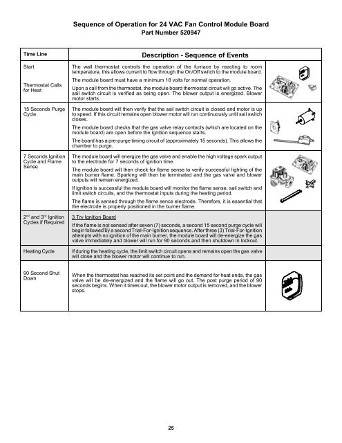
Sequence of Operation for 24 VAC Fan Control Module Board<br />
Part Number 520947<br />
Time Line<br />
Start<br />
Thermostat Calls<br />
for Heat<br />
15 Seconds Purge<br />
Cycle<br />
7 Seconds Ignition<br />
Cycle and Flame<br />
Sense<br />
nd<br />
rd<br />
2 and 3 Ignition<br />
Cycles if Required<br />
Heating Cycle<br />
Description - Sequence of Events<br />
The wall thermostat controls the operation of the furnace by reacting to room<br />
temperature, this allows current to flow through the On/Off switch to the module board.<br />
The module board must have a minimum 18 volts for normal operation.<br />
Upon a call from the thermostat, the module board thermostat circuit will go active. The<br />
sail switch circuit is verified as being open. The blower output is energized. Blower<br />
motor starts.<br />
The module board will then verify that the sail switch circuit is closed and motor is up<br />
to speed. If this circuit remains open blower motor will run continuously until sail switch<br />
closes.<br />
The module board checks that the gas valve relay contacts (which are located on the<br />
module board) are open before the ignition sequence starts.<br />
The board has a pre-purge timing circuit of (approximately 15 seconds). This allows the<br />
chamber to purge.<br />
The module board will energize the gas valve and enable the high voltage spark output<br />
to the electrode for 7 seconds of ignition time.<br />
The module board will then check for flame sense to verify successful lighting of the<br />
main burner flame. Sparking will then be terminated and the gas valve and blower<br />
outputs will remain energized.<br />
If ignition is successful the module board will monitor the flame sense, sail switch and<br />
limit switch circuits, and the thermostat inputs during the heating period.<br />
The flame is sensed through the flame sence electrode. Therefore, it is essential that<br />
the electrode is properly positioned in the burner flame.<br />
3 Try Ignition Board<br />
If the flame is not sensed after seven (7) seconds, a second 15 second purge cycle will<br />
begin followed by a second Trial-For-Ignition sequence. After three (3) Trial-For-Ignition<br />
attempts with no ignition of the main burner, the module board will de-energize the gas<br />
valve immediately and blower will run for 90 seconds and then shutdown in lockout.<br />
If during the heating cycle, the limit switch circuit opens and remains open the gas valve<br />
will close and the blower motor will continue to run.<br />
90 Second Shut<br />
Down<br />
When the thermostat has reached its set point and the demand for heat ends, the gas<br />
valve will be de-energized and the flame will go out. The post purge period of 90<br />
seconds begins. When it times out, the blower motor output is removed, and the blower<br />
stops.<br />
25