A-dec 500 12 O'Clock System
A-dec 500 12 O'Clock System
A-dec 500 12 O'Clock System
- No tags were found...

Create successful ePaper yourself
Turn your PDF publications into a flip-book with our unique Google optimized e-Paper software.
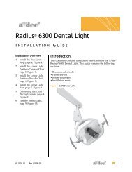
A-<strong>dec</strong> <strong>500</strong> <strong>12</strong> O’Clock <strong>System</strong><br />
I NSTALLATION GUIDE<br />
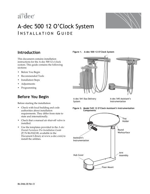
Introduction<br />
Figure 1. A-<strong>dec</strong> <strong>500</strong> <strong>12</strong> O’Clock <strong>System</strong><br />
This document contains installation<br />
instructions for the A-<strong>dec</strong> <strong>500</strong> <strong>12</strong> o’clock<br />
system. This guide contains the following<br />
sections:<br />
• Before You Begin<br />
• Recommended Tools<br />
• Installation Steps<br />
• Adjustments<br />
• Programming<br />
Before You Begin<br />
Before starting the installation:<br />
• Check with local building and code<br />
authorities about installation<br />
requirements. They differ from state to<br />
state and internationally.<br />
• Check that a manual air shut-off valve is<br />
installed.<br />
• Use the templates provided in the A-<strong>dec</strong><br />
Dental Furniture Pre-Installation Guide<br />
(P/N 86.0142.00, available in the<br />
Document Library at www.a-<strong>dec</strong>.com) to<br />
install the utilities.<br />
A-<strong>dec</strong> 541 Duo Delivery<br />
<strong>System</strong><br />
A-<strong>dec</strong> 545 Assistant’s<br />
Instrumentation<br />
Figure 2. Model 545 <strong>12</strong> O’Clock Assistant’s Instrumentation<br />
Components<br />
Assistant’s<br />
Instrumentation<br />
Tray<br />
Holder<br />
Round<br />
Worksurface<br />
Hub Cover<br />
Arm<br />
Assembly<br />
Floor Mount<br />
86.0466.00 Rev D
A-<strong>dec</strong> <strong>500</strong> <strong>12</strong> O’Clock <strong>System</strong> Installation Guide<br />
Recommended Tools<br />
• 1/2" concrete drill bit (<strong>12</strong>" long) or 3/8"<br />
wood drill bit<br />
• 7/16" open-end wrench<br />
• Adjustable wrench<br />
• Hex key set<br />
• Leveling device (approximately 8" long)<br />
• Phillips screwdriver<br />
• Ratchets (1/2" and 3/8" drive)<br />
• Standard screwdriver<br />
• 5/16" hex bit (3/8" drive)<br />
• 3/8" x 4" ratchet extension<br />
• 3/4" socket (deep well) with 6" extension<br />
Figure 3. Model 541 <strong>12</strong> O’Clock Delivery <strong>System</strong> Components<br />
Assistant’s<br />
Instrumentation<br />
Touchpad<br />
Doctor’s<br />
Instrumentation<br />
Holder<br />
Tray<br />
Holder<br />
Control<br />
Center<br />
Installation Steps<br />
Install Floor Mount<br />
Use the appropriate procedure for the type<br />
of floor construction present to install the <strong>12</strong><br />
o’clock delivery mount:<br />
1. Remove the top cardboard tray and<br />
round worksurface and set aside.<br />
2. Remove the mount from the plywood<br />
pallet and discard the screws securing<br />
the mount to the plywood.<br />
3. Locate mounting holes for drilling. Slide<br />
the floor mount into position.<br />
4. Attach the mount.<br />
Attach Mount - Concrete Floor<br />
1. Drill mounting holes, as shown in<br />
Figure 4:<br />
(1) Drill 1/2" (13 mm) diameter holes<br />
2 3/4" (69.9 mm) deep.<br />
(2) Remove debris from the holes.<br />
Figure 4. Attach Mount to Concrete Floor<br />
Arm Assembly<br />
TIP A <strong>12</strong>" long concrete drill bit is<br />
recommended for ease of drilling<br />
inside cabinet.<br />
2. Install four 1/2" X 4" concrete studs into<br />
the holes and tighten washers and nuts<br />
on the studs.<br />
2 86.0466.00 Rev D
A-<strong>dec</strong> <strong>500</strong> <strong>12</strong> O’Clock <strong>System</strong> Installation Guide<br />
Attach Mount - Non-Concrete Floor:<br />
1. Drill holes:<br />
(1) Drill 3/8" (9.5 mm) diameter holes.<br />
See Figure 5. Drill each hole 3 1/4"<br />
(82.5 mm) deep.<br />
(2) Remove debris from the holes.<br />
2. Attach the mount. Install four washers<br />
and 1/2" X 4" lag screws.<br />
Figure 5. Attach Mount to Non-Concrete Floor<br />
Complete Pre-Install Preparation<br />
1. Remove mounting screws from<br />
mounting bracket. See Figure 6.<br />
2. Unpack assembly from the box and cut<br />
zip ties to remove assembly from<br />
packing support.<br />
Figure 6. Remove Mounting Screws from Bracket<br />
Mount and Level the Arm Assembly<br />
1. Set the assembly on the floor mount and<br />
align to access the first set of mounting<br />
screw holes perpendicular to the cabinet<br />
or wall. See Figure 7..<br />
TIP Place the shortest piece of<br />
foam packaging underneath the far<br />
end of the arm assembly as a<br />
balance when you set the assembly<br />
on the floor mount.<br />
2. Insert the first set of mounting screws<br />
and loosely fasten.<br />
Figure 7. Insert First Set of Mounting Screws<br />
Arm Hub<br />
Floor Mount<br />
86.0466.00 Rev D 3
A-<strong>dec</strong> <strong>500</strong> <strong>12</strong> O’Clock <strong>System</strong> Installation Guide<br />
3. Level the hub by first loosening one<br />
mounting screw and then tightening the<br />
other mounting screw as necessary. See<br />
Figure 8. As a guide, place the level on<br />
the hub, parallel to the arm.<br />
Figure 8. Level the Hub<br />
To raise the long end of the arm:<br />
1. Loosen this screw.<br />
2. Tighten this screw.<br />
TIP The support arm balances on a<br />
pivot. To raise or lower the long<br />
side of the arm, adjust the screw<br />
nearest the cabinet or wall. (see<br />
Figure 8) Once the arm is level,<br />
tighten the second screw to hold the<br />
arm in place.<br />
4. Rotate the assembly parallel to the<br />
cabinet or wall to access the second set of<br />
mounting screw holes. See Figure 9.<br />
5. Insert the second set of mounting screws<br />
and loosely fasten.<br />
6. With the second set of mounting screws,<br />
level the hub by first loosening one<br />
mounting screw and then tightening the<br />
other mounting screw as necessary. Place<br />
a level on top of the hub as a guide.<br />
7. If you can jiggle the end of the arm up<br />
and down, then tighten the hub locknut.<br />
See Figure 8. When you rotate the arm,<br />
there should be slight resistance, and the<br />
arm should not drift.<br />
Plumb the Delivery <strong>System</strong><br />
1. Position the tubing between the floor<br />
mount bracket posts. Route the vacuum<br />
line last. Ensure all tubing is completely<br />
tucked down between the posts. See<br />
Figure 10.<br />
Hub Locknut<br />
Pivot Point<br />
Figure 9. Insert Second Set of Mounting Screws<br />
Arm Hub<br />
Floor Mount<br />
Figure 10. Position the Tubing<br />
Bracket Posts<br />
Floor Mount<br />
4 86.0466.00 Rev D
A-<strong>dec</strong> <strong>500</strong> <strong>12</strong> O’Clock <strong>System</strong> Installation Guide<br />
2. Route the tubing and connect matching<br />
tubing colors and patterns; for example,<br />
yellow dashed tubing to yellow dashed<br />
tubing. Refer to the flow diagram located<br />
either under the round worksurface or<br />
inside the control center housing. See<br />
Figure 11.<br />
Figure 11. Flow Diagram Location<br />
Flow diagram is under<br />
round worksurface.<br />
Flow diagram is inside<br />
control head housing.<br />
A-<strong>dec</strong> Model 541/545<br />
NOTE To remove the Model 541<br />
control center cover, locate the hole<br />
directly under the control center.<br />
Pull the covers apart. See Figure <strong>12</strong>.<br />
Figure <strong>12</strong>. Remove and Replace Control Center Cover<br />
CAUTION When removing or<br />
replacing covers, take care not to<br />
damage any wiring or tubing.<br />
Verify that the covers are secure<br />
after replacing them.<br />
3. Connect the vacuum:<br />
(1) Apply adhesive (not provided) to the<br />
vacuum connection.<br />
(2) Connect the vacuum line to the<br />
vacuum stub. Use the appropriate<br />
adapter provided in the kit.<br />
4. Connect the self-contained water bottle<br />
tubing. Refer to the instructions included<br />
with the water bottle.<br />
5. Connect the foot control (Model 541<br />
only):<br />
If attaching the delivery system to a<br />
cabinet:<br />
(1) Route the foot control tubing through<br />
the subbase. See Figure 13.<br />
Opening for<br />
Cover Removal<br />
Figure 13. Route Foot Control Tubing (Cabinet Mount)<br />
NOTE A-<strong>dec</strong> provides sufficient<br />
tubing length for a remote mount<br />
foot control.<br />
Foot Control<br />
Tubing Opening<br />
Power Supply<br />
Indicator Light<br />
Opening (optional)<br />
86.0466.00 Rev D 5
A-<strong>dec</strong> <strong>500</strong> <strong>12</strong> O’Clock <strong>System</strong> Installation Guide<br />
If attaching the delivery system against<br />
a wall:<br />
(1) Drill a 2 1/8" (54mm) hole.<br />
(2) Install tubing through the grommet.<br />
See Figure 14. Push the grommet and<br />
tubing through the wall plate.<br />
(3) Attach cover plate to wall. Use<br />
fasteners provided in wall plate kit.<br />
6. Attach the power supply. Refer to the<br />
flow diagram.<br />
For standard 300-watt power supplies<br />
only:<br />
(1) Splice the power supply tubing into a<br />
line with matching tubing. See<br />
Figure 15.<br />
NOTE If you must make<br />
connections to any configuration<br />
other than a standard 300-watt<br />
power supply, follow the<br />
instructions provided with that<br />
power supply. Remote power<br />
supply cables are available to<br />
connect the delivery system to the<br />
511 chair. Refer to the A-<strong>dec</strong><br />
Equipment Catalog for more<br />
information.<br />
Figure 14. Install Foot Control (Floor Mount)<br />
Grommet<br />
Figure 15. Attach Power Supply<br />
Four-Way<br />
Connection<br />
Foot Control<br />
Tubing<br />
Wall Plate<br />
Three-Way<br />
Connection from<br />
Power Supply<br />
7. Connect the air supply:<br />
(1) Purge the manual shutoff valves of<br />
debris.<br />
(2) Connect the air/filter regulator to the<br />
manual air shutoff valve.<br />
6 86.0466.00 Rev D
A-<strong>dec</strong> <strong>500</strong> <strong>12</strong> O’Clock <strong>System</strong> Installation Guide<br />
8. Wire the delivery system:<br />
(1) Connect all data lines from the<br />
delivery system. Use the data<br />
connector provided.<br />
CAUTION Circuit boards are<br />
sensitive to static electricity.<br />
Electrostatic Discharge (ESD)<br />
precautions are required when<br />
touching a circuit board or making<br />
connections to or from the circuit<br />
board. Circuit boards should be<br />
installed only by an electrician or<br />
qualified service person.<br />
(2) Connect the low-voltage power cables<br />
to the power supply.<br />
Install Ancillary Equipment<br />
Install any ancillary equipment (such as a<br />
curing light, etc.) for the A-<strong>dec</strong> <strong>500</strong><br />
<strong>12</strong> o’clock system. Use the instructions<br />
provided with the modules.<br />
Attach and Level<br />
Round Worksurface<br />
1. If necessary, remove the screws from the<br />
threaded standoffs in the metal plate<br />
underneath the worksurface. See<br />
Figure 16.<br />
2. Position the round worksurface on the<br />
worksurface support housing. Align the<br />
screw holes in the worksurface support<br />
housing with the threaded standoffs in<br />
the metal plate on the bottom of the<br />
worksurface.<br />
3. Insert the first set of worksurface screws<br />
and tighten until secure. Use two of the<br />
screws removed in Step 1 and a 1/8" hex<br />
key.<br />
4. Position the worksurface arm in a typical<br />
working position and center a level on<br />
the round worksurface over the support<br />
housing. See Figure 16.<br />
5. Adjust the two setscrews in the<br />
worksurface support housing until the<br />
surface is level. Use a 1/8" hex key.<br />
Figure 16. Attach and Level Round Worksurface<br />
A<br />
C<br />
(A) Second Set of Screws; (B) First Set of Screws; (C) Leveling<br />
Screws; (D) Worksurface Support Housing<br />
B<br />
D<br />
86.0466.00 Rev D 7
A-<strong>dec</strong> <strong>500</strong> <strong>12</strong> O’Clock <strong>System</strong> Installation Guide<br />
6. Insert the second set of worksurface<br />
screws. Tighten until the worksurface is<br />
secure.<br />
NOTE Do not overtighten the<br />
second set of worksurface screws,<br />
or the level may change.<br />
Attach Hub Mount Cover and Water<br />
Control Knobs<br />
1. Attach the snap-on cover on the hub<br />
mount. Use the cap screws provided and<br />
a 5/32" hex key. See Figure 17.<br />
CAUTION When removing or<br />
replacing covers, take care not to<br />
damage any wiring or tubing.<br />
Verify that the covers are secure<br />
after replacing them.<br />
Figure 17. Attach Hub Mount Cover<br />
Hub<br />
Cover<br />
Screw<br />
Holes<br />
Water<br />
Control<br />
Knobs<br />
2. Install water control knobs in the control<br />
center.<br />
Install the Tray<br />
1. Remove the plug and bumper from the<br />
tray mount. See Figure 18. The plug and<br />
bumper snap apart.<br />
2. Insert the tray bearing nut in the<br />
hexagonal depression in the underside of<br />
the bumper.<br />
3. Insert the tray bearing and secure by<br />
screwing in the bearing nut and bumper<br />
assembly.<br />
Test the Unit<br />
1. Fill the water bottle. Use the fill<br />
procedure specified by the dental staff.<br />
2. Turn master toggle on.<br />
3. Check the air pressure of the unit, it<br />
should be at 75 psi ± 5 psi.<br />
4. Check for air and water leaks while<br />
operating the syringe.<br />
Figure 18. Install the Tray<br />
Plug<br />
Bumper<br />
Tray<br />
Bearing<br />
Bumper<br />
Bearing<br />
Nut<br />
8 86.0466.00 Rev D
A-<strong>dec</strong> <strong>500</strong> <strong>12</strong> O’Clock <strong>System</strong> Installation Guide<br />
5. Test all the ancillary equipment.<br />
6. Replace all covers.<br />
CAUTION When removing or<br />
replacing covers, take care not to<br />
damage any wiring or tubing.<br />
Verify that the covers are secure<br />
after replacing them.<br />
NOTE To replace the cover, align<br />
the front and back halves and snap<br />
them together.<br />
Adjustments<br />
This section describes the steps to adjust the<br />
A-<strong>dec</strong> <strong>12</strong> o’clock delivery system. After<br />
installation, you can adjust:<br />
• Worksurface arm and instrumentation<br />
arm height<br />
• Handpiece controls<br />
○ Water coolant<br />
○ Air coolant<br />
○ Drive air flow<br />
• Touchpad settings<br />
○ Standard<br />
○ Deluxe<br />
Worksurface and Instrumentation<br />
Arm Height Adjustments<br />
To adjust the height of the worksurface and<br />
the instrumentation arm:<br />
1. Lift the upper part of the vertical post.<br />
See Figure 19.<br />
2. Slide the height adjustment ring to the<br />
desired position.<br />
3. Lower the vertical post onto the ring.<br />
Figure 19. Adjust Worksurface and Arm Height<br />
Height Adjustment Ring<br />
86.0466.00 Rev D 9
A-<strong>dec</strong> <strong>500</strong> <strong>12</strong> O’Clock <strong>System</strong> Installation Guide<br />
Handpiece Control Adjustments<br />
Water Coolant Flow<br />
The water coolant flow control adjusts the<br />
water to all handpieces. Use the adjustment<br />
key or a hex key to complete the adjustment:<br />
1. Lift the handpiece from the holder.<br />
2. Locate the water coolant flow controls.<br />
See Figure 20.<br />
3. Turn the water coolant on.<br />
4. Insert an adjustment key or hex key into<br />
the water coolant flow control for the<br />
handpiece being adjusted.<br />
5. Press the foot control to activate<br />
the handpiece.<br />
6. Adjust the water coolant flow to fit the<br />
user’s needs (normally 1-2 drops per<br />
second).<br />
• Turn the adjustment key to the right to<br />
<strong>dec</strong>rease flow.<br />
• Turn the adjustment key to the left to<br />
increase flow.<br />
Figure 20. Adjust Water and Air Coolant Flow<br />
Air Coolant Flow<br />
Adjustments<br />
Water Coolant<br />
Flow Adjustments<br />
NOTE Typically, one of the<br />
handpiece positions is air only.<br />
A-<strong>dec</strong> customizes handpiece<br />
configuration at time of order.<br />
Air Coolant Flow<br />
The air coolant flow control adjusts the air<br />
coolant flow to all handpieces. Use the<br />
adjustment key or a hex key to complete the<br />
adjustment:<br />
NOTE Adjusting the air coolant for<br />
one handpiece sets it for all of the<br />
positions.<br />
1. Lift the handpiece from the holder.<br />
2. Locate the air coolant control. See<br />
Figure 20.<br />
3. Use the Deluxe Touchpad to verify that<br />
the air coolant is on.<br />
10 86.0466.00 Rev D
A-<strong>dec</strong> <strong>500</strong> <strong>12</strong> O’Clock <strong>System</strong> Installation Guide<br />
4. Insert an adjustment key or hex key into<br />
the air coolant flow control.<br />
CAUTION Do not turn the drive air<br />
or air coolant adjustment keys too<br />
far. The stem may come completely<br />
out.<br />
5. Press the foot control to activate the<br />
handpiece.<br />
6. Adjust the air coolant flow to fit the<br />
user’s needs.<br />
• Turn the control to the right to <strong>dec</strong>rease<br />
flow.<br />
• Turn the control to the left to increase<br />
flow.<br />
Drive Air Pressure<br />
The drive air pressure controls adjust the<br />
pressure for each handpiece. See Figure 21.<br />
The digital drive air pressure gauge is<br />
located inside the control head. See<br />
Figure 22. The gauge indicates, in psi, the<br />
drive air pressure as it leaves the control<br />
block to the active handpiece.<br />
NOTE Use a handpiece pressure<br />
gauge attached to the handpiece<br />
tubing for exact drive air measurement.<br />
One bar equals 14.5 psi.<br />
Figure 21. Adjust Drive Air Pressure<br />
Drive Air<br />
Pressure<br />
Adjustments<br />
NOTE Refer to your handpiece<br />
documentation for the drive air<br />
pressure specification.<br />
To adjust the drive air pressure, complete<br />
these steps for each handpiece:<br />
Figure 22. Digital Drive Air Pressure Gauge<br />
1. If you have a Deluxe Touchpad, deselect<br />
the water coolant.<br />
2. Locate the drive air pressure gauge and<br />
controls inside the control head.<br />
3. Press the foot control.<br />
4. With the handpiece running, watch the<br />
gauge and adjust the handpiece drive air<br />
pressure to meet manufacturer’s<br />
specifications.<br />
Digital Drive Air<br />
Pressure Gauge<br />
on Circuit Board<br />
86.0466.00 Rev D 11
A-<strong>dec</strong> <strong>500</strong> <strong>12</strong> O’Clock <strong>System</strong> Installation Guide<br />
• Turn the control to the right to <strong>dec</strong>rease<br />
flow.<br />
• Turn the control to the left to increase<br />
flow.<br />
Touchpad Setting Adjustments<br />
A-<strong>dec</strong> touchpads control multiple chair and<br />
delivery system functions:<br />
• Standard Touchpad: Chair, light, and<br />
cuspidor controls. See Figure 23.<br />
• Deluxe Touchpad: Standard Touchpad<br />
settings plus setting for two modes:<br />
○<br />
○<br />
Standard Mode: air/water coolant,<br />
electric handpiece speed, scaler, and<br />
users A/B. See Figure 24.<br />
Endodontics Mode: Standard Mode<br />
settings plus file speed and torque<br />
limit, torque units, handpiece ratio,<br />
torque mode behavior, warning<br />
beeper, and handpiece light. See<br />
Figure 25 on page 13.<br />
Manual Operation<br />
You can use the touchpad buttons to<br />
manually operate:<br />
• Chair positions<br />
• Cupfill<br />
• Bowl rinse<br />
• Dental light<br />
• A-<strong>dec</strong> relay<br />
• Handpiece settings<br />
(Deluxe Touchpad only)<br />
Chair Positions: The chair positioning<br />
buttons allow you to manually move the<br />
chair base up/down and back up/down.<br />
ill: The cupfill function controls water flow<br />
from the cuspidor into a cup:<br />
• Press the cupfill button for a timed<br />
operation.<br />
• Press and hold the cupfill button for<br />
manual operation.<br />
Figure 23. Standard Touchpad<br />
D<br />
E<br />
H<br />
J<br />
K<br />
Item Description Item Description<br />
A Status Icon LED H Back Down<br />
B Dental Light 3-Way Switch J Entry/Exit<br />
C Cupfill K Position 1<br />
D Bowl Rinse L Base Down<br />
E Base Up M Position 3 (X-Ray/Rinse/<br />
Program)<br />
F Program Button N Position 2<br />
G Back Up<br />
Figure 24. Deluxe Touchpad Settings (Standard Mode)<br />
A<br />
E<br />
F<br />
G<br />
H<br />
J<br />
K<br />
L<br />
Item Description Item Description<br />
A<br />
B<br />
C<br />
F<br />
G<br />
L<br />
M<br />
N<br />
A Auxiliary Equipment J Memory Buttons (m1—m4)<br />
B A/B Operator Button K Endodontics Mode Toggle<br />
C Water Coolant Button L Program Button<br />
D Air Coolant Button M Speed Limit Setting<br />
E Memory Setting Indicator N Forward/Reverse Indicator<br />
F Water Coolant Indicator O Forward/Reverse Toggle<br />
G Air Coolant Indicator P Adjustment Buttons<br />
H A/B Operator Indicator<br />
B<br />
C<br />
D<br />
M<br />
N<br />
O<br />
P<br />
<strong>12</strong> 86.0466.00 Rev D
A-<strong>dec</strong> <strong>500</strong> <strong>12</strong> O’Clock <strong>System</strong> Installation Guide<br />
Bowl Rinse: Bowl rinse provides rinse water<br />
for the cuspidor bowl:<br />
• Press the bowl rinse button for a<br />
timed operation.<br />
• Press and hold the bowl rinse button for<br />
manual operation.<br />
NOTE If you press the bowl rinse<br />
button twice in less than two<br />
seconds, it switches to continuous<br />
operation mode. Press the button<br />
once to end the continuous bowl<br />
rinse mode.<br />
Dental Light: The dental light button on the<br />
touchpad functions as a three-way switch.<br />
You can turn the dental light on or off from<br />
either the touchpad or the dental light:<br />
• Press the dental light button to toggle<br />
between two intensity settings. The<br />
dental light toggles between compositemedium<br />
intensity or composite-high<br />
intensity settings.<br />
When the dental light is in composite<br />
mode, the indicator light next to the<br />
button blinks. The dental light has an<br />
auto on/off feature. When you use a<br />
programmed chair position (1 or 2) the<br />
dental light turns on when the chair<br />
reaches operating position.<br />
• Press Position 0 (entry/exit) and the<br />
dental light automatically turns off.<br />
Figure 25. Deluxe Touchpad Settings (Endodontics Mode)<br />
A<br />
B<br />
C<br />
D<br />
E<br />
5<br />
Item Description Item Description<br />
A Memory Setting Indicator G Warning Beep Indicator<br />
B A/B Operator Indicator H Endodontics Light Indicator<br />
C Attachment Ratio Setting J File Torque Limit/Unit<br />
Indicator<br />
D Memory Buttons (m1—m4) K Forward/Reverse and Torque<br />
Mode Indicator<br />
E Endodontics Mode Toggle<br />
Button<br />
L Forward/Reverse Toggle<br />
Button<br />
F File Speed Setting M Program Button<br />
F<br />
G<br />
H<br />
J<br />
K<br />
L<br />
M<br />
NOTE If Position 3 has been<br />
changed to a programmable<br />
position, the light operates the<br />
same as for Position 1 and 2.<br />
86.0466.00 Rev D 13
A-<strong>dec</strong> <strong>500</strong> <strong>12</strong> O’Clock <strong>System</strong> Installation Guide<br />
Factory Presets<br />
Chair positioning, light functions, cuspidor<br />
functions, handpiece behavior and speed are<br />
factory preset. Table 1 lists and defines the<br />
Standard Touchpad factory presets.<br />
Table 1. Standard Touchpad Factory Presets<br />
Icon Preset Definition<br />
Bowl rinse for 30 seconds.<br />
Cup fills for 2.5 seconds.<br />
Position 0—Chair moves to entry/exit position,<br />
dental light turns off.<br />
Program the Touchpad<br />
Use the Program button to:<br />
• Override or reset factory preset functions<br />
on either the Standard or Deluxe<br />
Touchpad.<br />
• Customize handpiece operations on the<br />
Deluxe Touchpad.<br />
For the Program button's location on the<br />
Standard Touchpad, see Figure 23. For its<br />
location on the Deluxe Touchpad, see<br />
figures 24 and 25.<br />
Program the Deluxe Touchpad<br />
In addition to the programmable features of<br />
the Standard Touchpad, the Deluxe<br />
Touchpad allows customizing of multiple<br />
users, the air/water coolant, electric<br />
handpieces, scaler, endodontics functions,<br />
and auxiliary equipment.<br />
Table 2 lists and defines the additional<br />
presets on a Deluxe Touchpad. For more<br />
information on customizing touchpad<br />
settings, refer to the A-<strong>dec</strong> <strong>500</strong> ® <strong>12</strong> O’Clock<br />
Delivery <strong>System</strong> Instructions For Use and the<br />
A-<strong>dec</strong> ® /W&H EA-51 LT Instructions for Use.<br />
Position 1—Chair moves base up and back up, dental<br />
light turns on and remains on.<br />
Position 2—Chair changes base up and back up,<br />
dental light turns on and remains on.<br />
Position 3—Chair moves to x-ray/rinse position,<br />
dental light turns off. Button toggles between<br />
x-ray/rinse position and chair’s previous position.<br />
Table 2. Deluxe Touchpad Additional Factory Presets<br />
Touchpad<br />
Icon<br />
Preset Definition<br />
• Air coolant on for all memory buttons<br />
(Standard Mode)<br />
• Air coolant off for all memory buttons<br />
(Endodontics Mode)<br />
• Water coolant on for all memory buttons<br />
(Standard Mode)<br />
• Water coolant off for all memory buttons<br />
(Endodontics Mode)<br />
• 2,000 RPM electric motor speed<br />
• 25% scaler throttle level<br />
• 10,000 RPM electric motor speed<br />
• 50% scaler throttle level<br />
• 20,000 RPM electric motor speed<br />
• 75% scaler throttle level<br />
• 36,000 RPM electric motor speed<br />
• 100% scaler throttle level<br />
14 86.0466.00 Rev D
A-<strong>dec</strong> <strong>500</strong> <strong>12</strong> O’Clock <strong>System</strong> Installation Guide<br />
Touchpad Troubleshooting<br />
The Deluxe Touchpad displays system and<br />
handpiece status to assist you in troubleshooting<br />
issues.<br />
<strong>System</strong> Status Icon<br />
The A-<strong>dec</strong> logo on the touchpad indicates<br />
the system status:<br />
• Solid blue—normal operation and power<br />
is on.<br />
• Blinking— chair stop plate or cuspidor<br />
limit switch is active. The icon returns to<br />
solid blue once you remove any<br />
obstructions.<br />
• Double Blink—a jumper on the chair<br />
circuit board is still in the factory default<br />
position.<br />
Touchpad Help Messages<br />
Help messages are displayed on the deluxe<br />
touchpad screen to provide information<br />
about why an operation is disabled. For<br />
information on help messages, refer to the<br />
Regulatory Information and Specifications<br />
document located in the Document Library<br />
at www.a-<strong>dec</strong>.com.<br />
86.0466.00 Rev D 15
A-<strong>dec</strong> <strong>500</strong> <strong>12</strong> O’Clock <strong>System</strong> Installation Guide<br />
Regulatory Information<br />
Regulatory information is provided with<br />
A-<strong>dec</strong> equipment as mandated by agency<br />
requirements. This information is delivered<br />
in the equipment’s Instructions for Use or the<br />
separate Regulatory Information and<br />
Specifications document. If you need this<br />
information, please go to the Document<br />
Library at www.a-<strong>dec</strong>.com.<br />
A-<strong>dec</strong> ® Headquarters<br />
2601 Crestview Drive<br />
Newberg, OR 97132 USA<br />
Tel: 1.800.547.1883 Within USA/Canada<br />
Tel: 1.503.538.7478 Outside USA/Canada<br />
Fax: 1.503.538.0276<br />
www.a-<strong>dec</strong>.com / www.a-<strong>dec</strong>.biz<br />
A-<strong>dec</strong> Inc. makes no warranty of any kind with regard to<br />
the content in this document including, but not limited<br />
to, the implied warranties of merchantability and fitness<br />
for a particular purpose.<br />
ÍvÈ.Ç$bÈ.00ÃÎ<br />
86.0466.00 Rev D<br />
Copyright 2013 A-<strong>dec</strong> Inc.<br />
All rights reserved.<br />
IGunbw5