ncr/doc/RealPOS/Other/5932_Keyboard/Technical_... - Alsys Data
ncr/doc/RealPOS/Other/5932_Keyboard/Technical_... - Alsys Data
ncr/doc/RealPOS/Other/5932_Keyboard/Technical_... - Alsys Data
- No tags were found...

You also want an ePaper? Increase the reach of your titles
YUMPU automatically turns print PDFs into web optimized ePapers that Google loves.
NCR <strong>5932</strong> USB <strong>Keyboard</strong><br />
User’s Guide<br />
B005-0000-1395<br />
Issue C
The product described in this book is a licensed product of NCR Corporation.<br />
NCR is a registered trademark of NCR Corporation.<br />
Pentium is a registered trademark of Intel Corporation.<br />
It is the policy of NCR Corporation (NCR) to improve products as new technology, components, software,<br />
and firmware become available. NCR, therefore, reserves the right to change specifications without prior<br />
notice.<br />
All features, functions, and operations described herein may not be marketed by NCR in all parts of the<br />
world. In some instances, photographs are of equipment prototypes. Therefore, before using this <strong>doc</strong>ument,<br />
consult with your NCR representative or NCR office for information that is applicable and current.<br />
To maintain the quality of our publications, we need your comments on the accuracy, clarity, organization,<br />
and value of this book.<br />
Address correspondence to:<br />
Manager, Information Products<br />
NCR Corporation<br />
2651 Satellite Blvd.<br />
Duluth, GA 30096<br />
Copyright © 2002<br />
By NCR Corporation<br />
Dayton, Ohio U.S.A.<br />
All Rights Reserved
iii<br />
Preface<br />
Audience<br />
Notice: This <strong>doc</strong>ument is NCR proprietary information and is not to<br />
be disclosed or reproduced without consent.<br />
Safety Requirements<br />
This device does not contain any user serviceable parts and should<br />
only be serviced by a qualified service technician.<br />
Caution: Before servicing the equipment plug your ground strap into<br />
a proper grounding outlet. Failure to do so could damage the<br />
equipment.<br />
Warning: Before servicing the keyboard, disconnect the AC power<br />
cord from the retail workstation or PC to which the keyboard is<br />
connected. Also disconnect the cables from the PC/workstation to the<br />
keyboard.<br />
Caution: To protect the internal circuitry from damage, unplug the<br />
AC power cord and then momentarily press the power switch ON to<br />
drain the power supply capacitance.<br />
Caution: The power supply cord is used as the main disconnect<br />
device. Ensure that the socket outlet is located/installed near the<br />
equipment and is easily accessible.<br />
Le cordon d’alimentation est utilisé comme interrupteur général. La<br />
prise de courant doit être située ou installée a proximite du matériel et<br />
être facile d’accés.
v<br />
Table of Contents<br />
Chapter 1: General Overview<br />
Introduction ...........................................................................................1-1<br />
109 Key USB <strong>Keyboard</strong>..................................................................1-1<br />
Model Number ...............................................................................1-2<br />
Major Model Code .....................................................................1-2<br />
Sub Model Code.........................................................................1-2<br />
Power Code.................................................................................1-2<br />
Language Code...........................................................................1-2<br />
Features ..................................................................................................1-3<br />
Keylock ............................................................................................1-3<br />
Speaker.............................................................................................1-3<br />
MSR ..................................................................................................1-4<br />
<strong>Keyboard</strong> Status LEDs...................................................................1-4<br />
Comparisons Between the PS/2 and USB <strong>Keyboard</strong>s.....................1-5<br />
Overview .........................................................................................1-5<br />
Summary .........................................................................................1-5<br />
Discussion........................................................................................1-6<br />
101-Key style keyboard .............................................................1-7<br />
Cappable Keys............................................................................1-8<br />
Double-High / Double-Wide Keys .........................................1-8<br />
<strong>Keyboard</strong> Programmability......................................................1-9<br />
Keylock ......................................................................................1-10<br />
Key Click ...................................................................................1-10<br />
Error Tone .................................................................................1-11<br />
MSR............................................................................................1-11<br />
Scanner port ..............................................................................1-11<br />
Additional port.........................................................................1-11
vi<br />
Power LED ................................................................................1-11<br />
Glide Pad...................................................................................1-12<br />
Fingerprint sensor....................................................................1-12<br />
Key Re-mapping Registry Manipulation Tool .........................1-13<br />
Chapter 2: Installation<br />
Environmental Conditions ..................................................................2-1<br />
Physical Environment....................................................................2-1<br />
Operating Range ........................................................................2-1<br />
Storage Range .............................................................................2-1<br />
Transit Range..............................................................................2-2<br />
Electrical Environment ..................................................................2-2<br />
Operational Environment .............................................................2-3<br />
System Configuration................................................................2-3<br />
Unit Setup ...................................................................................2-3<br />
Diagnostics..................................................................................2-3<br />
Physical Size ..........................................................................................2-4<br />
Installing the <strong>Keyboard</strong>........................................................................2-5<br />
Installation Goal..............................................................................2-5<br />
Cable Connections..........................................................................2-5<br />
USB <strong>Keyboard</strong> Scanner Connection.............................................2-6<br />
Powering Up..........................................................................................2-7<br />
Power Up Procedures ....................................................................2-7<br />
USB <strong>Keyboard</strong>.................................................................................2-8<br />
Keycode Charts...............................................................................2-9<br />
USB <strong>Keyboard</strong> Keycode Table .................................................2-9<br />
Labels....................................................................................................2-13<br />
External Nameplate......................................................................2-13<br />
Barcode/Serial Number Label....................................................2-14<br />
Weights and Measures Label......................................................2-15
vii<br />
Chapter 3: Programming<br />
Firmware ................................................................................................3-1<br />
USB <strong>Keyboard</strong> Capabilities...........................................................3-1<br />
FPGA Firmware Defaults..............................................................3-2<br />
Unique POS Capabilities ...............................................................3-2<br />
NCRUsb<strong>Keyboard</strong>Ctl HID usages ..........................................3-3<br />
Programmable Key Matrix .......................................................3-5<br />
Configurable Key Click Tone .................................................3-11<br />
NCR Platform Software Components...................................3-12<br />
NCR USB <strong>Keyboard</strong> Control Parameterization Registry<br />
Values ........................................................................................3-14<br />
NCR USB <strong>Keyboard</strong> Control <strong>Data</strong> Capture Registry<br />
Values ........................................................................................3-15<br />
Chapter 4: <strong>5932</strong> USB <strong>Keyboard</strong> Migration<br />
Overview................................................................................................4-1<br />
Legacy USB Option ........................................................................4-1<br />
Services Considerations.................................................................4-1<br />
7452and 7453 Terminal Requirements...............................................4-2<br />
Restrictions ......................................................................................4-2<br />
Power Up and Operating System Considerations ...........................4-3<br />
Questions and Answers .......................................................................4-4<br />
Chapter 5: Service<br />
Introduction ...........................................................................................5-1<br />
Safety Requirements.............................................................................5-1<br />
Problem Isolation Procedures .............................................................5-2<br />
Troubleshooting Table...................................................................5-3<br />
Removing Parts for Replacement .......................................................5-5<br />
USB <strong>Keyboard</strong>.................................................................................5-5<br />
Removing the MSR ....................................................................5-5
viii<br />
Replacing the MSR Swipe.........................................................5-8<br />
Replacing the Speaker ...............................................................5-9<br />
Replacing the Keylock .............................................................5-10<br />
Removing the <strong>Keyboard</strong> Membrane Sheet...........................5-11<br />
<strong>5932</strong> USB Kit and Spare Parts List ....................................................5-15<br />
<strong>5932</strong> USB Kit..................................................................................5-15<br />
MSR Cleaning Cards....................................................................5-15<br />
USB <strong>Keyboard</strong>...............................................................................5-15<br />
<strong>Keyboard</strong> Cleaning Procedures ........................................................5-16<br />
Index<br />
Revision Record<br />
Issue Date Remarks<br />
A Feb 02 First printing<br />
B May 02 Updated Migration chapter with PS/2 – USB<br />
comparison information<br />
B Sep 02 Modify keyboard layout and keycode tables for<br />
F13-F20 keys<br />
C Dec 02 Updated Programming Chapter with firmware<br />
interface information
ix<br />
Radio Frequency Interference Statements<br />
Federal Communications Commission (FCC)<br />
Information to User<br />
This equipment has been tested and found to comply with the limits for a Class A<br />
digital device, pursuant to Part 15 of FCC Rules. These limits are designed to provide<br />
reasonable protection against harmful interference when the equipment is operated in<br />
a commercial environment. This equipment generates, uses, and can radiate radio<br />
frequency energy and, if not installed and used in accordance with the instruction<br />
manual, may cause harmful interference to radio communications. Operation of this<br />
equipment in a residential area is likely to cause interference in which case the user<br />
will be required to correct the interference at his own expense.<br />
NCR is not responsible for any radio or television interference caused by unauthorized<br />
modification of this equipment or the substitution or attachment of connecting cables<br />
and equipment other than those specified by NCR. The correction of interference<br />
caused by such unauthorized modification, substitution or attachment will be the<br />
responsibility of the user. The user is cautioned that changes or modifications not<br />
expressly approved by NCR may void the user’s authority to operate the equipment.<br />
Canadian Department of Communications<br />
This Class A digital apparatus complies with Canadian ICES-003.<br />
This digital apparatus does not exceed the Class A limits for radio noise emissions<br />
from digital apparatus set out in the Radio Interference Regulations of the Canadian<br />
Department of Communications.<br />
Cet appareil numérique de la classe A est conforme à la norme NMB-003 du Canada.<br />
Le présent appareil numérique n'émet pas de bruits radioélectriques dépassant les<br />
limites applicables aux appareils numériques de la classe A prescrites dans le<br />
règlement sur le brouillage radioélectriques édicté par le ministrère des<br />
Communications du Canada.
x<br />
Voluntary Control Council For Interference (VCCI)<br />
International Radio Frequency Interference Statement<br />
Warning: This is a Class A product. In a domestic environment this product may<br />
cause radio interference in which case the user may be required to take adequate<br />
measures.
Chapter 1: General Overview<br />
Introduction<br />
This <strong>doc</strong>ument covers the Universal Serial Bus (USB) version keyboard<br />
Point-of-Service (POS) for the NCR <strong>5932</strong>. Also discussed is a<br />
comparison between the older <strong>5932</strong> PS/2 and the <strong>5932</strong> USB keyboards.<br />
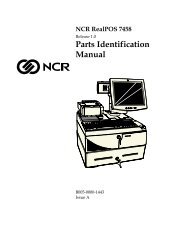
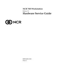
109 Key USB <strong>Keyboard</strong><br />
The 109-key USB keyboard is a multifunction keyboard that is two<br />
keyboards built into one.<br />
The keyboard consists of two major sections:<br />
• 38-key POS keyboard<br />
• Industry-standard alphanumeric PC keyboard<br />
19586<br />
The keyboard contains the key matrix and other POS-specific functions<br />
such as Keylock, speaker, system status indicator, and magnetic stripe<br />
reader (MSR). This <strong>5932</strong> keyboard also has a USB port to connect a<br />
Scanner or other USB device.
1-2 Chapter 1: General Overview<br />
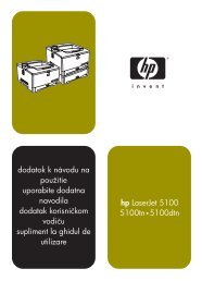
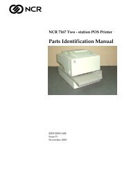
Model Number<br />
The keyboard's 12-digit model number is located on its serial number<br />
label. The model number identifies the keyboard features. The twelvedigit<br />
model number is defined in the following illustration.<br />
<strong>5932</strong> 50 06 90 90<br />
Class Number<br />
Major Model Code<br />
Language Code<br />
Power Code<br />
Sub Model Code<br />
19265<br />
Major Model Code<br />
Major Model Code Description<br />
50 USB <strong>Keyboard</strong><br />
Sub Model Code<br />
The following sub model codes identify features of the USB keyboard.<br />
Sub Model Code Description<br />
03 POS/USB <strong>Keyboard</strong> No MSR<br />
06 USB <strong>Keyboard</strong> with 3 Track MSR and Keylock<br />
07 USB <strong>Keyboard</strong> with Keylock and No MSR<br />
08 USB <strong>Keyboard</strong> with 3 Track MSR and No Keylock<br />
08 USB <strong>Keyboard</strong> with no Keylock and No MSR<br />
Power Code<br />
Power Code<br />
Description<br />
90 All Countries, 50/60 Hz<br />
Language Code<br />
Language Code Description<br />
90 No Language
Chapter 1: General Overview 1-3<br />
Features<br />
The NCR <strong>5932</strong> USB <strong>Keyboard</strong> supports the following features:<br />
• Keylock<br />
• Speaker<br />
• Magnetic Stripe Reader (MSR)<br />
• <strong>Keyboard</strong> Status LEDs<br />
Keylock<br />
The USB keyboard has a four-position Keylock. You can rotate the<br />
Keylock between specific positions by use of three keys. The positions<br />
are explained in the following table.<br />
Abbreviation Position Description<br />
Ex Exception Used by the customer or service<br />
representative to perform low<br />
level programming such as<br />
workstation diagnostics,<br />
configuring the workstation, or<br />
loading the workstation.<br />
L Locked Used to lock keyboard input to<br />
prohibit use of normal functions.<br />
R Register Used when performing normal<br />
retail mode functions.<br />
S Supervisor Used by the supervisor to<br />
provide highest level of<br />
workstation control in cases such<br />
as refunds and running totals.<br />
Speaker<br />
The programmable speaker is capable of generating key clicks and<br />
error tones.
1-4 Chapter 1: General Overview<br />
MSR<br />
The MSR is an optional feature that provides support for reading<br />
magnetically coded data cards. The keyboards support two different<br />
types of MSR:<br />
• ISO Tracks 1, 2, and 3<br />
• JIS-II and ISO Track 2<br />
The MSR head is connected to the MSR Amplifier Assembly via the<br />
MSR connector. The MSR Amplifier Assembly contains the<br />
amplification circuitry, a PCB, cable, and connectors.<br />
The MSR Amplifier Assembly is connected to the main PCB and<br />
mounted internally into the keyboard housing by the supplier on every<br />
unit. The intent is that when it becomes economically reasonable the<br />
MSR Amplifier Assembly (with modification) would be added the to<br />
MSR read head assembly kit and installed by the assemblers only when<br />
the customer requested the MSR option.<br />
<strong>Keyboard</strong> Status LEDs<br />
The keyboard has three status LED’s:<br />
• Num Lock<br />
• Caps Lock<br />
• Scroll Lock<br />
These features are used to provide the present state of the keyboard.<br />
The indicators are single color (Green) LED’s. When the system is off,<br />
no LED’s are illuminated.
Chapter 1: General Overview 1-5<br />
Comparisons Between the PS/2 and USB <strong>Keyboard</strong>s<br />
Overview<br />
Summary<br />
The NCR <strong>5932</strong> USB <strong>Keyboard</strong> is a replacement for its predecessor, the<br />
<strong>5932</strong> PS/2 (wedge), with features and advantages not present in the<br />
older product. This section is a discussion of those features with some<br />
explanation of the advantages.<br />
The NCR <strong>5932</strong> USB keyboard improves on its predecessor by taking<br />
advantage of features of USB to i<strong>ncr</strong>ease flexibility and connectivity.<br />
The major advances are:<br />
1. Glide Pad integration<br />
2. Full keyboard re-programmability<br />
3. Added general-purpose connectivity via on-board USB port<br />
4. Future optional fingerprint sensor module<br />
There are also minor technical improvements, primarily a benefit for<br />
systems integrators. One example is the ability for host software to<br />
detect the presence or absence of the MSR, Keylock, and Glide Pad.<br />
Another example is the use of standard USB protocols throughout and<br />
even standard USB Human Interface Desine (HID) device classes<br />
where such device standards exist. NCR went so far as to help develop<br />
an additional standard in the case of the MSR. Use of such standards<br />
eases the job of systems engineers and integrators.
1-6 Chapter 1: General Overview<br />
Discussion<br />
The NCR <strong>5932</strong> line of keyboards contain, most basically, a set of keys in<br />
a physical configuration that has been found useful to retailers. The<br />
keyboards also come with additional features, some optional, that add<br />
value to the retail environment. The following table lists these features.<br />
Following the table are paragraphs that more fully explain the<br />
terminology.<br />
Feature <strong>5932</strong> PS/2 (wedge) <strong>5932</strong> USB<br />
101-Key style keyboard Standard PS/2 Standard USB HID<br />
Cappable Keys 26 26<br />
Double-High /<br />
Double-Wide Keys<br />
<strong>Keyboard</strong><br />
Programmability<br />
Firmware Detected,<br />
limited keys<br />
Fixed, limited<br />
Fully Programmable<br />
Fully Programmable<br />
Keylock 4 position wedge 4 position USB HID<br />
Key Click Yes, programmable Yes, programmable<br />
Error Tone Yes, wedge Yes, USB HID<br />
MSR 3 track Wedge 3 track Standard USB<br />
HID<br />
Scanner port<br />
RS232, limited, prequalified<br />
Power LED Yes No<br />
See General Purpose USB<br />
Port<br />
Glide Pad No Yes, Standard USB HID<br />
Additional port No General Purpose USB<br />
port for Scanner or any<br />
USB 1.1 compliant<br />
device.<br />
Fingerprint sensor No Planned USB module<br />
replaces Keylock
Chapter 1: General Overview 1-7<br />
101-Key style keyboard<br />
The foundational difference between the NCR PS/2 keyboard and the<br />
NCR USB keyboard is the communications between the keyboard and<br />
the host computer. The PS/2 keyboard communicates using the PS/2<br />
communications protocol, which is bit-serial and operates at<br />
approximately 25 Kb. The USB keyboard uses the USB 1.1 protocol,<br />
which is a different bit-serial protocol that operates at either 1.5 or 12<br />
Mb. NCR’s keyboard operates at 12 Mb except for the Glide Pad, which<br />
operates at 1.5 Mb.<br />
Furthermore, each of these protocols includes a software layer. The<br />
PS/2 software layer is very simplistic, and presents a challenge when<br />
adding additional capabilities beyond the keyboard itself. All the<br />
added devices, such as MSR, Keylock, tone, and scanner are<br />
implemented as wedge devices. This means that these devices are<br />
wedged into the keyboard data stream and must spoof their way past<br />
the operating system to transfer data. This technique, though<br />
widespread, is burdened with problems, and is not standardized,<br />
resulting in installation and support difficulties.<br />
The USB software layer is standardized and well defined. It supports<br />
multiple simultaneous channels of communications, and permits<br />
additional capabilities to be added without negative impact.<br />
Furthermore, USB defines several levels of standards, including a<br />
standard for Human Interface Devices. This standard specifies<br />
behavior for many devices that are widely used in the computer<br />
industry, and permits proprietary extensions to be added for those<br />
devices that are less widely used. NCR’s USB keyboard includes both<br />
fully standard HID devices, such as the keyboard itself, the Glide Pad,<br />
and the MSR, and less-widely used and thus customized HID devices<br />
such as the Keylock and Error Tone.<br />
The USB keyboard implements a standard USB Hub internally. This<br />
hub provides independent connectivity to the several functional<br />
sections that comprise the keyboard.
1-8 Chapter 1: General Overview<br />
For many years, the standard in keyboards was the keyboard style<br />
known as 101-Key. In recent years, with the broad acceptance of<br />
Graphical User Interfaces, keyboards have added one or two GUI keys<br />
and current keyboards are now called 102-Key or 103-Key style. The<br />
NCR PS/2 keyboard does not contain these GUI keys. The NCR USB<br />
keyboard does not have reserved positions for those keys, but permits<br />
those keys to be added using the keyboard programmability (see<br />
<strong>Keyboard</strong> Programmability).<br />
Cappable Keys<br />
Both USB and PS/2 NCR keyboards include keys that accept customerspecified<br />
key caps and labels. For example, one customer may wish to<br />
include buttons for DEPT, CLASS, and SKU on his keyboard. A<br />
different customer may have no use for these keys, but may want<br />
TIRES, BATTERIES, and ACCESSORIES on specific keys. Cap-able<br />
keys allow for this customization.<br />
Double-High / Double-Wide Keys<br />
Along with cap-able keys comes the ability to put caps over pairs of<br />
plungers, resulting in larger keys. On a standard keyboard, the space<br />
bar, the Enter key, the Tab, Delete, Shift, Control, and Alt keys are all<br />
wider than the rest. These keys are implemented with one or two<br />
plungers, but they cannot be modified for different functionality. On<br />
NCR keyboards, the cap-able keys may be capped in pairs. Key caps<br />
are available that cover two plungers, either double-high or double-wide.<br />
When two keys are capped individually, the keyboard firmware must<br />
detect each one as a different key, and must send different messages to<br />
the host computer to indicate different keys were pressed. When the<br />
same two keys are capped together, the firmware must somehow know<br />
this and send only one message.
Chapter 1: General Overview 1-9<br />
With the <strong>5932</strong> PS/2, this is accomplished by using firmware that senses<br />
both plungers and the time lag between the plungers. If adjacent<br />
plungers are pressed within a certain interval, then the firmware only<br />
sends one of the two. Which one it sends is fixed, and the time lag is<br />
fixed. Thus, although this method works, it is subject to occasional<br />
error due to small mechanical tolerance problems. It is also somewhat<br />
limited in flexibility.<br />
With the <strong>5932</strong> USB, the keyboard is fully programmable. Two keys that<br />
are capped together can be programmed to literally BE the same key.<br />
(Duplicate messages are discarded.) Thus there is no limit to the<br />
flexibility, and no problem can be induced by the same minor<br />
mechanical problems experienced with the <strong>5932</strong> PS/2 keyboard.<br />
<strong>Keyboard</strong> Programmability<br />
The <strong>5932</strong> PS/2 keyboard includes the ability to select whether the<br />
keypad should be telephone- or calculator-style. This is implemented<br />
with a simple toggle that selects which layout is to be selected. No<br />
other programming is possible.<br />
The <strong>5932</strong> USB keyboard includes full programmability of the keyboard.<br />
Each and every key can be re-assigned as desired, and is only limited<br />
by the capabilities of a standard USB-HID keyboard. Based on registry<br />
entries, a program on the PC sends a complete keyboard layout matrix<br />
to the keyboard firmware. From that moment on, the firmware sends<br />
the newly assigned set of keys over the USB connection. No translation<br />
software is required in the host PC.<br />
New key values are assigned using registry entries. This means a<br />
keyboard can be replaced in the field without any extra programming<br />
steps. Once the terminal has been set up with key assignments, a<br />
replacement keyboard will automatically receive the programmed key<br />
assignments. Key assignments are sent from the registry whenever an<br />
NCR USB keyboard is connected to the PC, whether at power-on or<br />
hot-plugged.
1-10 Chapter 1: General Overview<br />
Each key can be programmed to be a dead key, one single key, or a<br />
two-key combination. Most keys will be single key values. However<br />
some keys may be programmed as a two-key combination. For<br />
example, the combination of Shift and F1 key values may be used to<br />
provide compatibility with the <strong>5932</strong> PS/2 keyboard. A double-zero key<br />
is another potential use for this feature. Any combination of up to two<br />
key values may be assigned to a single plunger on the keyboard.<br />
The registry values can be managed using a simple text editor along<br />
with the operating system supplied registry editor. Alternatively, a<br />
GUI utility (non-supported) is available for visually manipulating the<br />
key assignments in the registry (see Key Re-mapping Registry<br />
Manipulation Tool).<br />
Keylock<br />
Both PS/2 and USB keyboards include a four-position Keylock. All<br />
PS/2 keyboards have a Keylock, whereas in the USB keyboard, it is<br />
optional.<br />
The PS/2 keyboard implements the Keylock as a wedge device. The<br />
USB keyboard implements the Keylock as a separate HID device.<br />
Because USB is designed for plug-and-play (PnP), the presence or<br />
absence of the Keylock is easily detected by the host software.<br />
In both keyboards, placing the key in the L (Locked) position disables<br />
the keyboard. In the PS/2 keyboard, the MSR and the external scanner<br />
port are disabled. In the USB keyboard, the MSR, the Glide Pad and the<br />
external USB port are all disabled.<br />
Key Click<br />
Both PS/2 and USB keyboards provide a small speaker that can be<br />
used to make a key click sound. The exact sound made for key clicks is<br />
programmable in both devices, and the sounds available are<br />
comparable.
Chapter 1: General Overview 1-11<br />
Error Tone<br />
Both PS/2 and USB keyboards incorporate the ability for host software<br />
to evoke an error tone at the keyboard using the key click speaker. The<br />
capabilities are comparable.<br />
MSR<br />
Both PS/2 and USB keyboards provide an optional 3-track MSR in<br />
either ISO or JIS head configurations. The PS/2 keyboard cannot<br />
detect if the MSR is present.<br />
The USB keyboard implements the MSR as a separate USB HID device,<br />
conforming to the published HID standard for MSR devices. As with<br />
the Keylock, the PnP feature of USB communications makes it a simple<br />
matter for the host computer and thus the customer’s application to be<br />
aware of the presence or absence of the MSR.<br />
Scanner port<br />
The PS/2 keyboard contains an NCR-proprietary RJ-45 connection for<br />
RS-232 based scanners. This port has technical limitations and a limited<br />
subset of NCR scanners are qualified.<br />
The USB keyboard has no RJ-45 connector for RS-232 scanners.<br />
However see Additional Port.<br />
Additional port<br />
The PS/2 keyboard has no additional ports beyond the Scanner port.<br />
The USB keyboard provides a standard USB port connection to one of<br />
the internal hub’s ports. This connection permits a USB scanner, or for<br />
that matter, any standard USB device to be connected through the<br />
keyboard to the host computer.<br />
Power LED<br />
The PS/2 keyboard has an LED that indicates when power is present.<br />
The USB keyboard has no such LED.
1-12 Chapter 1: General Overview<br />
Glide Pad<br />
The PS/2 keyboard has no Mouse, Trackball, or Glide Pad capability.<br />
The USB keyboard supports an optional Glide Pad. The Glide Pad is a<br />
standard USB HID mouse-type device, seen within the host computer<br />
software as separate from each of the other independent USB devices.<br />
As with the other USB PnP components of the USB keyboard, the<br />
presence or absence of the Glide Pad is easily detected in the host<br />
computer.<br />
Fingerprint sensor<br />
The USB keyboard has been designed to accommodate a Fingerprint<br />
Sensor Module. This module replaces the Keylock module, and<br />
operates as another independent USB device through the internal hub.
Chapter 1: General Overview 1-13<br />
Key Re-mapping Registry Manipulation Tool<br />
A GUI Active-X control for Windows is available (though nonsupported)<br />
to simplify manipulation of the keyboard re-mapping<br />
registry entries.<br />
The Show Key #… radio buttons in the lower left allow the user to select<br />
whether to display the key tips, the HID usage values, or the NCRdesignated<br />
Key Number for display<br />
Clicking on an individual key highlights the key and enables the Key<br />
Number and Usage box. The current assignment is shown and two new<br />
key usages may be selected from the drop down boxes. Once selected,<br />
the new value can be assigned using the Set Usage button. The default<br />
value can be restored with the Restore Default button.<br />
A common need is to be able to toggle the keypad number layout<br />
between telephone and calculator style, so a special button is available<br />
for that function.
1-14 Chapter 1: General Overview<br />
The values currently stored in the Registry for NCR <strong>5932</strong> USB<br />
keyboards can be retrieved by clicking the Get Registry Map button. The<br />
only values stored in the registry are the values that are non-default.<br />
All of the keys can be restored to default values with the Restore All<br />
Defaults button.<br />
After assigning new values to keys or restoring default values, the<br />
values may be written to the registry using the Set Registry Map button.<br />
This is the only action that actually causes the registry to be written. All<br />
other actions are held in program memory for display on the GUI.<br />
Only clicking this button will cause the current values to be saved.<br />
The Done/Exit button exits the control. If the Done/Exit key is pressed<br />
without pressing the Set Registry Map button, then no modifications are<br />
saved.
Chapter 2: Installation<br />
Environmental Conditions<br />
Physical Environment<br />
This section lists the physical and electrical environments required for<br />
the NCR <strong>5932</strong> USB <strong>Keyboard</strong>s.<br />
Operating Range<br />
Condition<br />
Range<br />
Temperature<br />
5°C to 45°C (40°F to 113°F)<br />
Relative Humidity 10% to 90%<br />
Non-condensing<br />
Barometric Pressure 15.2 to 0.2 psi up to a<br />
maximum of 9,850 feet<br />
Storage Range<br />
Condition<br />
Range<br />
Temperature<br />
-10° to 50°C (14°F to 120°F)<br />
Temperature Change 15°C (27°F) per hour max.<br />
Relative Humidity 10% to 90%
2-2 Chapter 2: Installation<br />
Transit Range<br />
Electrical Environment<br />
Condition<br />
Range<br />
Temperature<br />
-40° to 60°C (-40°F to 140°F)<br />
Temperature Change 20°C (36°F) per hour max.<br />
Relative Humidity 5% to 95%<br />
Condensation may occur when equipment is transferred from cold to<br />
warm areas during shipment. If flash condensation has occurred, only<br />
operate the keyboard after the equipment has dried and been stabilized<br />
to the operating environment.<br />
The electrical environment required for the keyboard module is listed<br />
as follows.<br />
Parameter Symbol Min Max<br />
Supply voltage to keyboard VIN 4.75V 5.25v<br />
Supply current to keyboard I IN 500 mA<br />
Supply voltage to USB Port VOUT 4.75V 5.5V<br />
Supply current to USB Port IOUT 100mA<br />
Note: The user programmable speaker tone function on the USB<br />
keyboards is not supported when the keyboard is connected to a<br />
standard PC. The standard PC keyboard voltage tolerance is not<br />
sufficient to handle the extra power requirements of the programmable<br />
speaker tone. Only the default keyclick and error tones are supported<br />
on a PC.<br />
Caution: Be sure to turn off your PC or retail workstation BEFORE<br />
you plug in the keyboard. “Hot plugging” can result in damage to your<br />
PC due to the i<strong>ncr</strong>eased power requirements of the USB keyboards.
Chapter 2: Installation 2-3<br />
Operational Environment<br />
The following parameters apply to keyboard operations.<br />
System Configuration<br />
No keyboard configuration is required at installation time. The<br />
keyboard is configured at the time of manufacture by default to<br />
recognize the Ctrl-Alt-Del key combination for system reset.<br />
Unit Setup<br />
No unit setup is required at installation time, unless configuration<br />
must be changed from factory defaults.<br />
Diagnostics<br />
Upon Powering Up or receiving a reset, the keyboard initializes by:<br />
• Clearing RAM<br />
• Resetting the indicator lights<br />
Additionally, if a stuck key condition is detected, the USB HID<br />
<strong>Keyboard</strong> usage ID of the stuck key is returned following the<br />
successful status.
2-4 Chapter 2: Installation<br />
Physical Size<br />
184 mm<br />
(7.25 in.)<br />
455 mm<br />
(17.9 in.)<br />
45 mm<br />
(1.7 in.)<br />
35 mm<br />
(1.4 in.)<br />
19650
Chapter 2: Installation 2-5<br />
Installing the <strong>Keyboard</strong><br />
Installation Goal<br />
Cable Connections<br />
Caution: The power supply cord is used as the main disconnect<br />
device. Ensure that the socket outlet is located/installed near the<br />
equipment and is easily accessible.<br />
Le cordon d’alimentation est utilisé comme interrupteur général. La<br />
prise de courant doit être située ou installée a proximite du matériel et<br />
être facile d’accés.<br />
The goal for installing the keyboards is for a reasonably trained<br />
operator or store manager to fully install the workstation in less than<br />
10 minutes.<br />
To qualify as “reasonably trained” an installer or store manager must<br />
be fluent with the terminology and basic technology of PC hardware<br />
and software. This level of knowledge can typically be found in an<br />
individual who has installed several PC systems, and who routinely<br />
uses a PC for personal or business computing.<br />
The keyboard communicates with the host system via a single USB<br />
compatible interface. They keyboard cable is a USB 1.1 compliant cable.<br />
The mating connector to the host is a UBS Series “A” plug and the<br />
keyboard side of the cable is enclosed with sufficient strain relief. The<br />
keyboard conforms to all operational and non-operational vibration<br />
and shock requirements.<br />
The length of the cable from the keyboard cabinet to the end of the<br />
connector is 70.1+ 0.5 inches. One end of the cable is to be internally<br />
connected but not soldered and clamped to the printed circuit board of<br />
the keyboard.
2-6 Chapter 2: Installation<br />
The pin assignments for the connector are shown below.<br />
Contact Number Signal Name Typical Wiring Assignment<br />
1 VBUS Red<br />
2 D- White<br />
3 D+ Green<br />
4 GND Black<br />
Shell Shield Drain Wire<br />
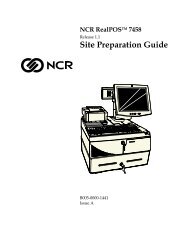
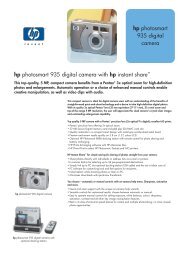
USB <strong>Keyboard</strong> Scanner Connection<br />
The USB keyboard may be connected to a USB hand held scanner or<br />
other USB device as shown in the following illustration.<br />
USB<br />
Cable<br />
USB<br />
Connector<br />
19587
Chapter 2: Installation 2-7<br />
Powering Up<br />
This section describes powering up the workstation and the initial<br />
checkout procedures after all hardware has been installed.<br />
Note: No keyboard configuration is required at installation time. The<br />
keyboard is configured at the time of manufacture by default to<br />
recognize the Ctrl-Alt-Del key combination for system reset.<br />
Note: No unit setup is required at installation unless configuration<br />
must be changed from factory defaults.<br />
Powering up procedures is described for the keyboard when<br />
configured with:<br />
• PC<br />
Power Up Procedures<br />
• 7452/53 Workstation<br />
• 7451 & 7456 Workstations<br />
Plug the USB keyboard Cord into a USB port on the workstation.<br />
1. Turn the Keylock to the Ex position.<br />
2. Power on the workstation.
2-8 Chapter 2: Installation<br />
USB <strong>Keyboard</strong><br />
The USB keyboard key layout is shown below.<br />
1 2 3<br />
7 11 12<br />
78<br />
79<br />
84<br />
85<br />
15<br />
4 5<br />
6 8<br />
9 10<br />
13 14<br />
91<br />
92<br />
98<br />
99<br />
Num<br />
Caps<br />
Sc ro ll<br />
105<br />
106<br />
115<br />
Lo c k<br />
Loc k<br />
Loc k<br />
16<br />
17<br />
18<br />
19<br />
20<br />
21<br />
22<br />
23<br />
24<br />
25<br />
26<br />
27<br />
28<br />
30<br />
112<br />
113<br />
114<br />
31<br />
32<br />
33<br />
34<br />
35<br />
36<br />
37<br />
38<br />
39<br />
40<br />
41<br />
42 43<br />
44<br />
86<br />
87<br />
88<br />
80 82<br />
83<br />
45<br />
46<br />
47<br />
48<br />
49<br />
50<br />
51<br />
52<br />
53<br />
54<br />
55<br />
56<br />
58<br />
93<br />
94<br />
95<br />
81<br />
89<br />
90<br />
59<br />
61<br />
62<br />
63<br />
64<br />
65<br />
66<br />
67<br />
68<br />
69<br />
70<br />
72<br />
100<br />
101<br />
102<br />
103<br />
96<br />
97<br />
73 74 75<br />
76 77 107 108 109<br />
110<br />
111<br />
104<br />
Insert<br />
Home<br />
Page<br />
Up<br />
Pause<br />
Scrol<br />
Lock<br />
F1 F2 F3 F4<br />
ESC<br />
Delete<br />
End<br />
Page<br />
Down<br />
Print<br />
Screen<br />
Num<br />
Lock<br />
F5 F6 F7 F8<br />
Num<br />
Caps<br />
Scrol<br />
F9 F10 F11<br />
Lock Lock Lock<br />
~ !<br />
1<br />
@<br />
2<br />
#<br />
3<br />
$<br />
4<br />
%<br />
5<br />
6<br />
&<br />
7<br />
*<br />
8<br />
(<br />
9<br />
)<br />
0 -<br />
+<br />
=<br />
Ba c ksp a c e<br />
F12<br />
LShft<br />
+F3<br />
LShft<br />
+F4<br />
Tab<br />
Q<br />
W<br />
E<br />
R<br />
T<br />
Y<br />
U<br />
I<br />
O<br />
P<br />
{ }<br />
[ ]<br />
7<br />
8 9<br />
LShft<br />
+F5<br />
LShft<br />
+F6<br />
LShft<br />
+F7<br />
Caps<br />
Lock<br />
A<br />
S<br />
D<br />
F<br />
G<br />
H<br />
J<br />
K<br />
L<br />
CR<br />
4<br />
5<br />
6<br />
LShft<br />
+F8<br />
LShft<br />
+F9<br />
LShft<br />
+F10<br />
Ctrl<br />
Shift<br />
Z<br />
A l t<br />
X<br />
C<br />
V<br />
B<br />
N<br />
M<br />
<<br />
,<br />
> <br />
Alt<br />
/<br />
Shift<br />
Ctrl<br />
1<br />
0<br />
2<br />
3<br />
E<br />
N<br />
T<br />
E<br />
R<br />
+ *<br />
- /<br />
19759
Chapter 2: Installation 2-9<br />
Keycode Charts<br />
The following tables correlate the keyboard key number, unshifted<br />
character and scan code for the USB keyboard<br />
USB <strong>Keyboard</strong> Keycode Table<br />
Key Number Unshifted Character USB HID <strong>Keyboard</strong> Usage ID (h)<br />
1 Insert 49<br />
2 Home 4A<br />
3 Page Up 4B<br />
4 Delete 4C<br />
5 End 4D<br />
6 Page Down 4E<br />
7 ↑ (up arrow) 52<br />
8 ← (left arrow) 50<br />
9 ↓ (down arrow) 51<br />
10 → (right arrow) 4F<br />
11 Pause 48<br />
12 Scroll Lock 47<br />
13 Print Screen 46<br />
14 Num Lock 53<br />
15 Esc 29<br />
16 ‘ (apostrophe) 35<br />
17 1 1E<br />
18 2 1F<br />
19 3 20<br />
20 4 21<br />
21 5 22<br />
22 6 23<br />
23 7 24<br />
24 8 25<br />
25 9 26
2-10 Chapter 2: Installation<br />
Key Number Unshifted Character USB HID <strong>Keyboard</strong> Usage ID (h)<br />
26 0 27<br />
27 — 2D<br />
28 = 2E<br />
30 Backspace 2A<br />
31 Tab 2B<br />
32 q 14<br />
33 w 1A<br />
34 e 08<br />
35 r 15<br />
36 t 17<br />
37 y 1C<br />
38 u 18<br />
39 i 0C<br />
40 o 12<br />
41 p 13<br />
42 [ 2F<br />
43 ] 30<br />
44 \ 31<br />
45 Caps Lock 39<br />
46 a 04<br />
47 s 16<br />
48 d 07<br />
49 f 09<br />
50 g 0A<br />
51 h 0B<br />
52 j 0D<br />
53 k 0E<br />
54 l 0F<br />
55 ; 33<br />
56 ‘ (single quote) 34<br />
58 Return 28<br />
59 Shift (left side) E1
Chapter 2: Installation 2-11<br />
Key Number Unshifted Character USB HID <strong>Keyboard</strong> Usage ID (h)<br />
61 z 1D<br />
62 x 1B<br />
63 c 06<br />
64 v 19<br />
65 b 05<br />
66 n 11<br />
67 m 10<br />
68 , (comma) 36<br />
69 . (period) 37<br />
70 / (forward slash 38<br />
72 Shift (right side) E5<br />
73 Ctrl (left side) E0<br />
74 Alt (left side) E2<br />
75 Space 2C<br />
76 Alt (right side) E6<br />
77 Ctrl (right side) E4<br />
78 F1 3A<br />
79 F2 3B<br />
80 Left Shift-F5 E13E<br />
81 Left Shift-F8 E141<br />
82 Left Shift-F6 E13F<br />
83 Left Shift-F7 E140<br />
84 F3 3C<br />
85 F4 3D<br />
86 7 5F<br />
87 8 60<br />
88 9 61<br />
89 Left Shift-F9 E142<br />
90 Left Shift-F10 E143<br />
91 F5 3E<br />
92 F6 3F<br />
93 4 5C
2-12 Chapter 2: Installation<br />
Key Number Unshifted Character USB HID <strong>Keyboard</strong> Usage ID (h)<br />
94 5 5D<br />
95 6 5E<br />
96 + 57<br />
97 * 55<br />
98 F7 40<br />
99 F8 41<br />
100 1 59<br />
101 2 5A<br />
102 3 5B<br />
103 ENTER 58<br />
104 / 54<br />
105 F9 42<br />
106 F10 43<br />
107 0 62<br />
108 0 62<br />
109 . 63<br />
110 Enter 58<br />
111 - 56<br />
112 F12 45<br />
113 Left Shift-F3 E13C<br />
114 Left Shift-F4 E13D<br />
115 F11 44
Chapter 2: Installation 2-13<br />
Labels<br />
External Nameplate<br />
Each keyboard is marked with the NCR part number and revision<br />
level. The suppliers' sequential serial or tracking number and the<br />
suppliers' UL and CSA files numbers, around its respective marking.
2-14 Chapter 2: Installation<br />
Barcode/Serial Number Label<br />
The <strong>5932</strong> USB <strong>Keyboard</strong> has a barcode/serial number label as specified<br />
in NCR <strong>doc</strong>ument 497-0422987. The label material is:<br />
NCR System Media 901840 Thermal Top Coated Permanent Adhesive.<br />
An example is shown below.<br />
NCR<br />
<strong>5932</strong>-MMSM-VFLL<br />
70-NNNNNNNN<br />
Mfg. Date: xx/xx/xx<br />
19911<br />
Where:<br />
MM = 2 digit Major Model Code<br />
SM = 2 digit Sub Model Code<br />
VF = 2 digit Voltage and Frequency Code<br />
LL = 2 digit Language Code<br />
NN = 8 digit Serial Number (Unique Number for each keyboard)<br />
Mfg Date = 2 digit month/2 digit day/2 digit year of manufacture
Chapter 2: Installation 2-15<br />
Weights and Measures Label<br />
The <strong>5932</strong> USB <strong>Keyboard</strong> has a Weights and Measures label. The label<br />
material is 3M #7380 tamper indicating polyester, with 3M #7745<br />
imprintable laminate.<br />
An example is shown below.
Chapter 3: Programming<br />
Firmware<br />
USB <strong>Keyboard</strong> Capabilities<br />
The NCR USB <strong>Keyboard</strong> is a multifunction device comprised of several<br />
functions, including a keyboard switch matrix and a speaker. Both of<br />
these functions are controlled by a single field programmable gate<br />
array (FPGA).<br />
The keyboard matrix translates between a key switch physical location<br />
and the key data reported to the host PC. This matrix is programmable.<br />
The matrix may be replaced in whole or in part, permitting any key to<br />
be mapped to any function.<br />
The FPGA has the ability to sound a short chirp whenever a key is<br />
pressed, providing auditory feedback to an operator of the keyboard.<br />
This auditory feedback is optional. The FPGA may be configured to<br />
make the sound or not to make the sound, depending on the particular<br />
application.<br />
The FPGA has no static memory and thus cannot retain any settings<br />
after power loss. Thus, each time the system to which this keyboard is<br />
connected is powered-up, or any time the keyboard is connected to a<br />
powered system, the FPGA must be informed of any pertinent settings.<br />
This function is an ActiveX/COM control (NCRUsb<strong>Keyboard</strong>Ctl) that<br />
provides a mechanism by which the keyboard features of “key click<br />
sound” and “key translation matrix” can be set.<br />
The keyboard firmware is standard USB compatible keyboard<br />
firmware with added extensions for POS-specific functions.
3-2 Chapter 3: Programming<br />
The keyboard supports the following minimum standard PC keyboard<br />
capabilities:<br />
• System Reset (Control-Alt-Delete)<br />
The keyboard has additional capabilities unique to the POS<br />
environment. The keyboard firmware supports the following POS<br />
functions:<br />
• Programmable keyboard matrix<br />
• Configurable keyclick tone<br />
• Calculator or Telephone style numeric keypad configuration<br />
FPGA Firmware Defaults<br />
During USB initialization all USB devices are required to enumerate.<br />
Each device reports its data and ID to the host where the Host USB<br />
driver sends the report to the corresponding USB Device Driver.<br />
Power Up and Reset POS Default Conditions:<br />
• Default keyboard matrix configuration<br />
• Calculator style numeric keypad configuration<br />
• Num Lock On.<br />
Unique POS Capabilities<br />
The keyboard firmware supports the following POS-specific extensions<br />
to the standard PC firmware:<br />
• Programmable Key Matrix<br />
• Configurable Keyclick Tone<br />
• NCR Platform Software Components
Chapter 3: Programming 3-3<br />
NCRUsb<strong>Keyboard</strong>Ctl HID usages<br />
NCRUsb<strong>Keyboard</strong>Ctl employs industry standard and NCR Proprietary<br />
HID Usage interfaces to exercise the keyboard control programming<br />
capability of the firmware. The NCR Proprietary usages are contained<br />
in the following table:<br />
Table 1: NCR Proprietary HID Usages<br />
Usage<br />
HID_USAGE_PAGE_NCR_MISC<br />
KEYLOCK<br />
KEYBOARD_TONE<br />
KEYBOARD_MAP<br />
Hexadecimal Value<br />
0xFF8F<br />
0x01<br />
0x02<br />
0x03<br />
KEY_CLICK_INFO<br />
ERROR_TONE<br />
0x11<br />
0x12<br />
TONE FREQUENCY<br />
TONE DURATION<br />
TONE VOLUME<br />
0x21<br />
0x22<br />
0x23<br />
KEY_MATRIX_USAGE<br />
0x31
3-4 Chapter 3: Programming<br />
The report descriptors as emitted by the HID device should be<br />
consulted as the authority for the format of the reports. Software<br />
should access fields using report descriptor-based techniques and<br />
should not assume that all revisions of the product use identical report<br />
descriptors. The following provides interpretation information for<br />
these reports.<br />
Keylock hardware HID interface: The keylock reports its<br />
positions as HID buttons. The positions are assigned as follows:<br />
• Button 1 = Ex<br />
• Button 2 = L<br />
• Button 3 = R<br />
• Button 4 = S.<br />
Tone hardware interface: The ErrorTone usage collects a tone<br />
output report that sounds an immediate tone. The KeyClick usage<br />
collects a tone output report that sets the sound made for a key<br />
click. The units for Duration are milliseconds. The volume is a value<br />
between Logical_Minimum (silent) and Logical_Maximum (greatest<br />
volume). The tone is an index from Table 2: Note Numbers and<br />
Frequencies.<br />
The MSR interface: The MSR conforms to the USB HID standard<br />
for MSRs as described in the HID Usage Tables for POS, Ver 1.02,<br />
see http://www.usb.org/developers/hidpage.html#pos.<br />
The Key Matrix: The Key Matrix report contains an overlay for the<br />
keyboard look-up table. It is organized in FPGA Offset order, and<br />
contains pairs of 8-bit usages, one pair per key position. Values of<br />
zero produce no usage report. Two different usages produce two<br />
simultaneous usages being reported. The number of positions is<br />
given by the report descriptor.
Chapter 3: Programming 3-5<br />
Programmable Key Matrix<br />
The keyboard matrix is completely programmable, translating between<br />
a key switch physical location and the key data reported to the host PC.<br />
Through this keyboard provision, you can switch the numeric keypad<br />
layout from the default calculator layout to a telephone layout by<br />
organizing the keyboard matrix to mimic either mode of operation.<br />
Note: If you change the numeric keypad layout, you must also<br />
physically remove and swap the key caps on the first and third rows of<br />
the keypad. The key codes for the numeric keypad are identical to the<br />
IBM PS/2, 101-key keyboard.<br />
Double-high/Double-wide Keys<br />
Several keys on the keyboard can accept optional keycaps that cover<br />
two keys to produce double-high or double-wide keys. When you<br />
press a double-high or double-wide keycap, the keyboard firmware<br />
sends the keycode for both keys. When usages are the same, only one<br />
keycode is sent. Using the programmable key matrix feature, the<br />
keyboard matrix can be programmed to support double-high or<br />
double-wide keys by specifying the same key code for both key<br />
locations supported by the key cap.<br />
<strong>Keyboard</strong> Matrix for <strong>5932</strong> USB <strong>Keyboard</strong> (PID 0x0320)<br />
The keyboard matrix comprises a list of key numbers and respective<br />
positions within the keyboard translation table. The default keyboard<br />
map for the <strong>5932</strong> USB <strong>Keyboard</strong> (PID 0x0320) is as follows:<br />
Sorted by Key Number Sorted by Offset Sorted by Usage<br />
Key<br />
FPGA<br />
FPGA Key<br />
FPGA Key<br />
Number Usage Offset<br />
Offset Number Usage Usage Offset Number<br />
1 49 0 0 1 49 0 104 29<br />
2 4A 16 1 16 35 0 105 57<br />
3 4B 24 2 31 2B 0 106 60<br />
4 4C 8 3 96 57 0 108 71<br />
5 4D 40 4 45 39 0 111 116
3-6 Chapter 3: Programming<br />
Key<br />
FPGA<br />
FPGA Key<br />
FPGA Key<br />
Number Usage Offset<br />
Offset Number Usage Usage Offset Number<br />
6 4E 48 5 15 29 0 112 117<br />
7 52 32 6 109 63 0 113 118<br />
8 50 64 7 110 58 0 114 119<br />
9 51 56 8 4 4C 0 116 120<br />
10 4F 72 9 17 1E 0 117 121<br />
11 48 88 10 32 14 0 119 122<br />
12 47 80 11 83 E140 0 120 123<br />
13 46 102 12 46 4 0 121 124<br />
14 53 96 13 61 1D 0 122 125<br />
15 29 5 14 89 E142 0 124 126<br />
16 35 1 15 108 62 0 125 127<br />
17 1E 9 16 2 4A 0 127 128<br />
18 1F 17 17 18 1F 4 12 46<br />
19 20 25 18 33 1A 5 45 65<br />
20 21 33 19 78 3A 6 29 63<br />
21 22 41 20 47 16 7 28 48<br />
22 23 49 21 62 1B 8 26 34<br />
23 24 57 22 97 55 9 36 49<br />
24 25 65 23 85 3D 10 61 67<br />
25 26 73 24 3 4B 11 53 66<br />
26 27 81 25 19 20 12 74 40<br />
27 2D 89 26 34 8 13 82 41<br />
28 2E 97 27 115 44 14 10 32<br />
29 0 104 28 48 7 15 34 35
Chapter 3: Programming 3-7<br />
Key<br />
FPGA<br />
FPGA Key<br />
FPGA Key<br />
Number Usage Offset<br />
Offset Number Usage Usage Offset Number<br />
30 2A 86 29 63 6 16 20 47<br />
31 2B 2 30 99 41 17 42 36<br />
32 14 10 31 84 3C 18 58 38<br />
33 1A 18 32 7 52 19 37 64<br />
34 8 26 33 20 21 20 25 19<br />
35 15 34 34 35 15 21 33 20<br />
36 17 42 35 82 E13F 22 41 21<br />
37 1C 50 36 49 9 23 49 22<br />
38 18 58 37 64 19 24 57 23<br />
39 0C 66 38 95 5E 25 65 24<br />
40 12 74 39 81 E141 26 73 25<br />
41 13 82 40 5 4D 27 81 26<br />
42 2F 90 41 21 22 28 94 58<br />
43 30 98 42 36 17 29 5 15<br />
44 31 92 43 80 E13E 30 98 43<br />
45 39 4 44 50 0A 31 92 44<br />
46 4 12 45 65 5 33 84 55<br />
47 16 20 46 102 5B 34 93 56<br />
48 7 28 47 101 5A 35 1 16<br />
49 9 36 48 6 4E 36 69 68<br />
50 0A 44 49 22 23 37 77 69<br />
51 0B 52 50 37 1C 38 85 70<br />
52 0D 60 51 103 58 39 4 45<br />
53 0E 68 52 51 0B 40 59 98
3-8 Chapter 3: Programming<br />
Key<br />
FPGA<br />
FPGA Key<br />
FPGA Key<br />
Number Usage Offset<br />
Offset Number Usage Usage Offset Number<br />
54 0F 76 53 66 11 41 30 99<br />
55 33 84 54 100 59 42 83 105<br />
56 34 93 55 114 E13D 43 63 106<br />
57 0 105 56 9 51 44 27 115<br />
58 28 94 57 23 24 45 87 112<br />
59 E1 123 58 38 18 46 102 13<br />
60 0 106 59 98 40 47 80 12<br />
61 1D 13 60 52 0D 48 88 11<br />
62 1B 21 61 67 10 49 0 1<br />
63 6 29 62 92 3F 50 64 8<br />
64 19 37 63 106 43 51 56 9<br />
65 5 45 64 8 50 52 32 7<br />
66 11 53 65 24 25 53 96 14<br />
67 10 61 66 39 0C 54 103 104<br />
68 36 69 67 88 61 55 22 97<br />
69 37 77 68 53 0E 56 101 111<br />
70 38 85 69 68 36 57 3 96<br />
71 0 108 70 94 5D 58 51 103<br />
72 E5 126 71 86 5F 58 7 110<br />
73 E0 115 72 10 4F 59 54 100<br />
74 E2 107 73 25 26 60 79 87<br />
75 2C 109 74 40 12 61 67 88<br />
76 E6 110 75 113 E13D 62 100 107<br />
77 E4 118 76 54 0F 62 15 108
Chapter 3: Programming 3-9<br />
Key<br />
FPGA<br />
FPGA Key<br />
FPGA Key<br />
Number Usage Offset<br />
Offset Number Usage Usage Offset Number<br />
78 3A 19 77 69 37 63 6 109<br />
79 3B 95 78 93 5C 0A 44 50<br />
80 E13E 43 79 87 60 0B 52 51<br />
81 E141 39 80 12 47 0C 66 39<br />
82 E13F 35 81 26 27 0D 60 52<br />
83 E140 11 82 41 13 0E 68 53<br />
84 3C 31 83 105 42 0F 76 54<br />
85 3D 23 84 55 33 1A 18 33<br />
86 5F 71 85 70 38 1B 21 62<br />
87 60 79 86 30 2A 1C 50 37<br />
88 61 67 87 112 45 1D 13 61<br />
89 E142 14 88 11 48 1E 9 17<br />
90 E143 99 89 27 2D 1F 17 18<br />
91 3E 91 90 42 2F 2A 86 30<br />
92 3F 62 91 91 3E 2B 2 31<br />
93 5C 78 92 44 31 2C 109 75<br />
94 5D 70 93 56 34 2D 89 27<br />
95 5E 38 94 58 28 2E 97 28<br />
96 57 3 95 79 3B 2F 90 42<br />
97 55 22 96 14 53 3A 19 78<br />
98 40 59 97 28 2E 3B 95 79<br />
99 41 30 98 43 30 3C 31 84<br />
100 59 54 99 90 E143 3D 23 85<br />
101 5A 47 100 107 62 3E 91 91
3-10 Chapter 3: Programming<br />
Key<br />
FPGA<br />
FPGA Key<br />
FPGA Key<br />
Number Usage Offset<br />
Offset Number Usage Usage Offset Number<br />
102 5B 46 101 111 56 3F 62 92<br />
103 58 51 102 13 46 4A 16 2<br />
104 54 103 103 104 54 4B 24 3<br />
105 42 83 104 29 0 4C 8 4<br />
106 43 63 105 57 0 4D 40 5<br />
107 62 100 106 60 0 4E 48 6<br />
108 62 15 107 74 E2 4F 72 10<br />
109 63 6 108 71 0 5A 47 101<br />
110 58 7 109 75 2C 5B 46 102<br />
111 56 101 110 76 E6 5C 78 93<br />
112 45 87 111 116 0 5D 70 94<br />
113 E13C 75 112 117 0 5E 38 95<br />
114 E13D 55 113 118 0 5F 71 86<br />
115 44 27 114 119 0 E0 115 73<br />
116 0 111 115 73 E0 E1 123 59<br />
117 0 112 116 120 0 E13C 75 113<br />
118 0 113 117 121 0 E13D 55 114<br />
119 0 114 118 77 E4 E13E 43 80<br />
120 0 116 119 122 0 E13F 35 82<br />
121 0 117 120 123 0 E140 11 83<br />
122 0 119 121 124 0 E141 39 81<br />
123 0 120 122 125 0 E142 14 89<br />
124 0 121 123 59 E1 E143 99 90<br />
125 0 122 124 126 0 E2 107 74
Chapter 3: Programming 3-11<br />
Key<br />
FPGA<br />
FPGA Key<br />
FPGA Key<br />
Number Usage Offset<br />
Offset Number Usage Usage Offset Number<br />
126 0 124 125 127 0 E4 118 77<br />
127 0 125 126 72 E5 E5 126 72<br />
128 0 127 127 128 0 E6 110 76<br />
Configurable Key Click Tone<br />
The FPGA has the ability to sound a short chirp whenever a key is<br />
pressed, providing auditory feedback to an operator of the keyboard.<br />
This auditory feedback is optional. The FPGA may be configured to<br />
make the sound or not to make the sound, depending on the particular<br />
application.<br />
USB <strong>Keyboard</strong> Tone Frequencies<br />
The frequency is transmitted to the FPGA as a Note Number. Note<br />
numbers are equivalent to specific frequencies. The note number sent<br />
to the FPGA is selected by rounding the requested frequency to the<br />
nearest frequency number given by the table of Note Numbers (N) and<br />
Frequencies (freq) listed in the following table.<br />
Table 2: Note Numbers and Frequencies<br />
Note N freq N freq N freq N freq N freq N freq<br />
A 0 28 24 110 48 440 72 1760 96 7040 120 28160<br />
Bb 1 29 25 117 49 466 73 1865 97 7459 121 29834<br />
B 2 31 26 123 50 494 74 1976 98 7902 122 31609<br />
C 3 33 27 131 51 523 75 2093 99 8372 123 33488<br />
Db 4 35 28 139 52 554 76 2217 100 8870 124 35479<br />
D 5 37 29 147 53 587 77 2349 101 9397 125 37589<br />
Eb 6 39 30 156 54 622 78 2489 102 9956 126 39824<br />
E 7 41 31 165 55 659 79 2637 103 10548 127 42192<br />
F 8 44 32 175 56 698 80 2794 104 11175
3-12 Chapter 3: Programming<br />
Note N freq N freq N freq N freq N freq N freq<br />
Gb 9 46 33 185 57 740 81 2960 105 11840<br />
G 10 49 34 196 58 784 82 3136 106 12544<br />
Ab 11 52 35 208 59 831 83 3322 107 13290<br />
A 12 55 36 220 60 880 84 3520 108 14080<br />
Bb 13 58 37 233 61 932 85 3729 109 14917<br />
B 14 62 38 247 62 988 86 3951 110 15804<br />
C 15 65 39 262 63 1047 87 4186 111 16744<br />
Db 16 69 40 277 64 1109 88 4435 112 17740<br />
D 17 73 41 294 65 1175 89 4699 113 18795<br />
Eb 18 78 42 311 66 1245 90 4978 114 19912<br />
E 19 82 43 330 67 1319 91 5274 115 21096<br />
F 20 87 44 349 68 1397 92 5588 116 22351<br />
Gb 21 92 45 370 69 1480 93 5920 117 23680<br />
G 22 98 46 392 70 1568 94 6272 118 25088<br />
Ab 23 104 47 415 71 1661 95 6645 119 26580<br />
N<br />
Note: The frequency “f” is given by the equation :<br />
12<br />
f ≈ 27 .5×<br />
2<br />
This table provides the full set of frequencies defined, however the<br />
hardware itself may not generate all of these frequencies, and the<br />
frequencies actually generated may not exactly match any of the<br />
frequencies listed. Lower frequency numbers produce lower tones, and<br />
higher frequency numbers produce higher tones.<br />
NCR Platform Software Components<br />
NCR provides three platform software components for configuring the<br />
keyboard: the NCR USB <strong>Keyboard</strong> Control, the Set USB Key Matrix<br />
application and the Set USB Key Clicks application.
Chapter 3: Programming 3-13<br />
NCR USB <strong>Keyboard</strong> Control<br />
NCRUsbKeyClickCtl is an ActiveX control that contains a method for<br />
setting the key clicks SetClicks, and a method for downloading the key<br />
translation matrix information, SetKeyMatrix.<br />
The SetClicks method examines all currently-enumerated HID devices,<br />
finds those with a Vendor-ID equal to NCR’s assigned Vendor ID<br />
(0x0404). Among all qualified devices found, each device is searched<br />
for a KEY_CLICK_INFO feature report that contains Volume, Frequency,<br />
and Duration usages. When a matching device is found, that device’s<br />
product ID (PID) is used to locate keyclick values within the Registry.<br />
The values found in the registry are sent to the device in the<br />
KEY_CLIC_INFO feature report.<br />
Each time SetClicks is invoked, it reads Volume, Frequency, and Duration<br />
keyclick parameters from the registry. If these parameters are not<br />
found in the registry, default values are written to the registry, and<br />
these default values are used. This causes the registry to contain the<br />
values most recently sent to NCR HID KeyClick devices.<br />
The default values for Volume, Frequency, and Duration,<br />
SetUsbKeyClick are 15, 1318, and 16, respectively.<br />
The Set<strong>Keyboard</strong>Matrix method examines all currently-enumerated<br />
HID devices, finds those with a Vendor-ID equal to NCR’s assigned<br />
Vendor ID (0x0404). Among all qualified devices found, each device is<br />
searched for a KEYBOARD_MAP feature report that contains an array<br />
of KEY_MATRIX_USAGE usages, When a matching device is found,<br />
that device’s PID is used to locate Key Matrix entries in the Registry. If<br />
no Key Matrix values are found for that specific PID, no Key Matrix<br />
download is performed.<br />
For each KEYBOARD_MAP device located, Set<strong>Keyboard</strong>Matrix creates a<br />
full default keyboard matrix that duplicates the factory-default matrix<br />
of the specific product located. Next, the registry is read for<br />
replacement values within the <strong>Keyboard</strong> Matrix. All registry values<br />
found in the appropriate registry key are replaced within the default<br />
matrix. Finally, the full key matrix as modified by registry values is<br />
sent to the keyboard using the KEYBOARD_MAP feature report.
3-14 Chapter 3: Programming<br />
NCR USB <strong>Keyboard</strong> Control Parameterization Registry Values<br />
Program Parameterization Registry values appear under the registry<br />
key: [HKEY_LOCAL_MACHINE\SOFTWARE\NCR\USB<strong>Keyboard</strong>\PID_0320\]<br />
Table 3: Key-Value Definitions<br />
Keyword 1 Value (Decimal numbers) Default Registry<br />
KeyClick\frequency 2 A frequency between<br />
27Hz and 42192 Hz<br />
1760 DWORD<br />
KeyClick\volume 2 A value between 0<br />
and 15<br />
KeyClick\duration 2<br />
KeyMatrix\keynumber 3<br />
15 DWORD<br />
A number of<br />
milliseconds (0 - 1023)<br />
the sound should be<br />
produced<br />
23 DWORD<br />
A single keyboard<br />
usage to be installed<br />
for keynumber<br />
per key DWORD<br />
matrix<br />
section for<br />
PID_0320<br />
1 Keywords are not case sensitive.<br />
2 The Keywords frequency, volume, and duration and their values as sent<br />
to the keyboard tone device are written to the registry. This enables a<br />
systems management program to determine current keyclick settings.<br />
3 The keynumber value name is a decimal number that must be one of<br />
the possible key numbers for the designated product. For example,<br />
“Set<strong>Keyboard</strong>KeyEntry(0320)” requires the registry contain a key<br />
named HKLM\Software\NCR\USB<strong>Keyboard</strong>\PID_0320\KeyMatrix, and<br />
under this key there must be one or more values with names “1”<br />
through “128” that correspond to the key numbers.
Chapter 3: Programming 3-15<br />
NCR USB <strong>Keyboard</strong> Control <strong>Data</strong> Capture Registry Values<br />
NCR <strong>Data</strong> Capture Registry values appear under the registry key:<br />
[HKEY_LOCAL_MACHINE\SOFTWARE\NCR\NCRUsb<strong>Keyboard</strong>Ctl\<strong>Data</strong>Capture]<br />
"DcapControl"="10 (Hex destination(s): 1=DCap App, 2=Debugger,<br />
4=File; 10/20/40 for immediate)"<br />
"DcapFile"="C:\\Ncr<strong>Data</strong>Cap.log"<br />
"DcapFileMax"="0 (Max KB of data cap file)"<br />
"DcapMask"="00000003 (Hex mask of events to capture)"<br />
"DcapTime"="1F00 (Hex time option(s): 100=m:s, 300=h:m:s,<br />
700=m/d h:m:s; 800+digits=millisec; 1000=threadid)"<br />
"DcapVersion"="1.1.3"<br />
"DcapLinePrefix"="NCRUsb<strong>Keyboard</strong>Ctl "<br />
Set DcapMask to 0x01 to receive only Error messages. Set to 0x02 or<br />
higher receives all messages.<br />
Set USB Key Matrix Application<br />
SetUsbKeyMatrix is a Windows application for the Desktop O/S<br />
versions (Windows 98se, Windows 2000) that uses the<br />
NCRUsb<strong>Keyboard</strong>Ctl control to set a keyboard matrix map. The<br />
application operates as a memory-resident background process for a<br />
duration that may be specified on the command line. If no duration is<br />
specified, the application remains resident until terminated by user<br />
action. While resident, the application receives device-attachment<br />
notifications for HID devices, and when these are received, invokes<br />
the NCRUsb<strong>Keyboard</strong>Ctl control to set the keyboard matrix map.<br />
Command-line parameters may include a value for the runtime<br />
duration. If specified, the application remains resident only for the<br />
requested duration. This permits the application to be used only<br />
during defined events such as system start-up, and after which the<br />
application will no longer remain resident in memory. The commandline<br />
parameters may also specify that a background memory-resident<br />
instance of the application should be terminated. In this case, the<br />
application only terminates the background instance, and does not<br />
remain resident itself or invoke the control to set the keyboard matrix<br />
map.
3-16 Chapter 3: Programming<br />
SetUsbKeyMatrix may be launched “by hand” using the Windows Start<br />
> Run option, or any equivalent shortcut technique (desktop, quicklaunch<br />
pad, menu). If started in this manner, the command line can<br />
optionally contain strings of the form “keyword{= value}”, where<br />
keyword is one of the defined parameters, and value is an optional<br />
numeric value to be applied to that key.<br />
The following table gives the available command-line parameters.<br />
Table 4: Command-line Parameters<br />
Keyword 1 Value (Decimal numbers) Value<br />
Close Close any background session found n/a<br />
runtime<br />
A number of seconds to remain resident,<br />
waiting for additional devices to<br />
initialize.<br />
0 = indefinitely<br />
1 Keywords are not case sensitive, and may be abbreviated to 3 or more<br />
characters.<br />
Set USB Key Clicks Application<br />
SetUsbKeyClick is a Windows application for the Desktop O/S versions<br />
(Windows 98se, Windows 2000) that uses the NCRUsb<strong>Keyboard</strong>Ctl<br />
control to set keyclick tone parameters. The application operates as a<br />
memory-resident background process for a duration that may be<br />
specified on the command line. If no duration is specified, the<br />
application remains resident until terminated by user action. While<br />
resident, the application receives device-attachment notifications for<br />
HID devices, and when these are received, invokes the<br />
NCRUsb<strong>Keyboard</strong>Ctl control to set keyclick tone parameters.
Chapter 3: Programming 3-17<br />
Command-line parameters may include a value for the runtime<br />
duration. If specified, the application remains resident only for the<br />
requested duration. This permits the application to be used only<br />
during defined events such as system start-up, and after which the<br />
application will no longer remain resident in memory. The commandline<br />
parameters may also specify that a background memory-resident<br />
instance of the application should be terminated. In this case, the<br />
application only terminates the background instance, and does not<br />
remain resident itself or invoke the control to set keyclick parameters.<br />
SetUsbKeyClick may be launched “by hand” using the Windows Start ><br />
Run option, or any equivalent shortcut technique (desktop, quicklaunch<br />
pad, menu). If started in this manner, the command line can<br />
optionally contain strings of the form “keyword{= value}”, where<br />
keyword is one of the defined parameters, and value is an optional<br />
numeric value to be applied to that key.<br />
The following table gives the available command-line parameters.<br />
Table 5: Command-line Parameters<br />
Keyword 1 Value (Decimal numbers) Value<br />
close Close any background session found n/a<br />
runtime<br />
A number of seconds to remain resident,<br />
waiting for additional devices to initialize.<br />
0 = indefinitely<br />
1 Keywords are not case sensitive, and may be abbreviated to 3 or more<br />
characters.
Chapter 4: <strong>5932</strong> USB <strong>Keyboard</strong> Migration<br />
Overview<br />
Legacy USB Option<br />
Services Considerations<br />
This chapter contains information about the functionality of the <strong>5932</strong><br />
USB <strong>Keyboard</strong> on the operating systems supported by the 7452 and<br />
7453 terminals. Topics include:<br />
• 7452and 7453 Terminal requirements<br />
• Power up and operating system considerations<br />
• Questions and Answers<br />
MS-DOS and Windows NT operating systems do not recognize USB. A<br />
new BIOS option, Legacy USB, is available in BIOS Version 2.2.1.1 for<br />
NCR 7452 and 7453 terminals. The default setting is Disabled. Enabling<br />
the Legacy USB option in the 7452 terminal BIOS makes the <strong>5932</strong> USB<br />
<strong>Keyboard</strong> look like a PS/2 keyboard to MS-DOS. For more information<br />
about 7452 BIOS Setup options, refer to the NCR 7452 Hardware User's<br />
Guide (BD20-1373-C).<br />
When performing any of the following DOS services, the Legacy USB<br />
option must be enabled prior to using the service.<br />
• DOS Loadable Diagnostics<br />
• OS Recovery<br />
• BIOS Flash Update
4-2 Chapter 4: <strong>5932</strong> USB <strong>Keyboard</strong> Migration<br />
7452and 7453 Terminal Requirements<br />
BIOS Version 2.2.1.1 or later is required. Terminals with previous BIOS<br />
versions do not have the capability to support Legacy USB.<br />
Restrictions<br />
The <strong>5932</strong> USB <strong>Keyboard</strong> is not supported under DOS and Windows<br />
NT operating environments. This keyboard is supported under DOS<br />
for the purpose of servicing the terminal only. See the Services<br />
Considerations section.
Chapter 4: <strong>5932</strong> USB <strong>Keyboard</strong> Migration 4-3<br />
Power Up and Operating System Considerations<br />
The following illustration provides an overview of what occurs when<br />
the terminal is turned on and the system boot occurs in the following<br />
operating/runtime environment.<br />
• BIOS Version 2.2.1.1 or later<br />
• <strong>5932</strong> USB <strong>Keyboard</strong><br />
• Windows 95, Windows 98, Windows 2000, or Windows XP<br />
operating system<br />
Power up<br />
POS<br />
BIOS Init<br />
USB <strong>Keyboard</strong><br />
input accepted<br />
- Use F2 for Setup<br />
- Use Enter to remove<br />
Splash Screen<br />
- Navigate through<br />
Setup<br />
BIOS Init<br />
finishes<br />
Disables<br />
Legacy<br />
USB<br />
Approximately when NCR Splash<br />
Screen/bitmap is removed or<br />
BIOS Level Zeros are removed<br />
OS Start<br />
to Initialize<br />
OS USB<br />
<strong>Keyboard</strong><br />
Drivers are<br />
installed<br />
No USB<br />
<strong>Keyboard</strong><br />
input accepted<br />
USB <strong>Keyboard</strong><br />
input accepted<br />
W98 - F8 to enter<br />
Safe Mode<br />
W2K - Boot Timer<br />
Choice Menu<br />
- Check Disk Prompt<br />
- Profile Choice<br />
Login<br />
Prompt<br />
19756
4-4 Chapter 4: <strong>5932</strong> USB <strong>Keyboard</strong> Migration<br />
Questions and Answers<br />
Q: Why would someone want to enable Legacy USB<br />
A: This option is needed when using DOS OS Recovery, DOS BIOS<br />
Flash, or DOS Loadable Diagnostics.<br />
Q: If Legacy USB is enabled for the purpose of Diagnostics, OS<br />
Recovery or BIOS Flash what must be done when finished<br />
A: Disable Legacy USB before booting into the OS.<br />
Q: What happens when Legacy USB is enabled and you boot into the<br />
OS<br />
A: Windows NT and Windows 2000 will blue screen or hang due to a<br />
Video BIOS conflict. Windows 98 Restarts when you do a shutdown<br />
(see Microsoft’s KBase article Q250635).<br />
Q: Are there any exceptions that need to be noted if Legacy USB is<br />
disabled for Windows9x, Windows 2000, or Windows XP<br />
A: Yes, there is a window from the time the BIOS completes<br />
initialization and the operating system installs it’s native USB<br />
<strong>Keyboard</strong> support where the keyboard cannot be used. For example:<br />
pressing F8 under Windows 98 in order to go into Safe Mode or<br />
pressing any key under Windows 2000 to accelerate the boot.ini timer.<br />
Refer to the Power Up and Operating System Considerations flow chart on<br />
the previous page.<br />
Q: Which operating systems does NCR support with the <strong>5932</strong> USB<br />
<strong>Keyboard</strong><br />
A: Depending on the POS platform, NCR supports Windows 95,<br />
Widnows 98, Windows 2000, and Windows XP as the operating<br />
environment. NCR also supports the <strong>5932</strong> USB <strong>Keyboard</strong> under DOS<br />
for the purpose of DOS Loadable Diagnostics, OS Recovery, or Flash<br />
Update only.
Chapter 5: Service<br />
Introduction<br />
This chapter contains information about the service and repair of the<br />
NCR <strong>5932</strong> USB <strong>Keyboard</strong>s. Topics include:<br />
• Safety requirements<br />
• Problem isolation procedures<br />
• Removing parts for replacement<br />
• Spare parts list<br />
Safety Requirements<br />
• <strong>Keyboard</strong> cleaning procedures<br />
Carefully follow these safety requirements before servicing the<br />
keyboards.<br />
This device does not contain any user serviceable parts and should<br />
only be serviced by a qualified service technician.<br />
Caution: Before servicing the equipment plug your ground strap into<br />
a proper grounding outlet. Failure to do so could damage the<br />
equipment.<br />
Warning: Before servicing the keyboard, disconnect the AC power<br />
cord from the retail workstation or PC to which the keyboard is<br />
connected. Also disconnect the cables from the PC/workstation to the<br />
keyboard.<br />
Caution: To protect the internal circuitry from damage, unplug the<br />
AC power cord and then momentarily press the power switch ON to<br />
drain the power supply capacitance.
5-2 Chapter 5: Service<br />
Caution: The power supply cord is used as the main disconnect<br />
device. Ensure that the socket outlet is located/installed near the<br />
equipment and is easily accessible.<br />
Le cordon d’alimentation est utilisé comme interrupteur général. La<br />
prise de courant doit être située ou installée a proximite du matériel et<br />
être facile d’accés.<br />
Problem Isolation Procedures<br />
NCR offers both on-site and mail-in service for the NCR <strong>5932</strong> USB<br />
<strong>Keyboard</strong>s.<br />
Before calling for service or mailing in your unit for repair, step<br />
through the problem isolation procedures on the next page to make<br />
sure the keyboard is the module in need of repair. Also, your answers<br />
to these questions may speed the servicing of your keyboard.
Chapter 5: Service 5-3<br />
Troubleshooting Table<br />
The following table provides general troubleshooting tips. If you<br />
experience a problem with your keyboard, explore the possible<br />
solutions in this table before replacing any component in the system.<br />
Symptom Probable Cause Solution<br />
<strong>Keyboard</strong> not<br />
working<br />
Keylock in “L” position<br />
(LED green)<br />
Turn Keylock to another<br />
position<br />
Some keys on the<br />
keyboard not<br />
working<br />
<strong>Keyboard</strong> not powered<br />
(LED off)<br />
<strong>Keyboard</strong> cable not<br />
connected<br />
<strong>Keyboard</strong> “hot plugged”<br />
into workstation with<br />
workstation powered on.<br />
Check PC power<br />
Connect keyboard cable<br />
to PC USB port<br />
Re-boot the system<br />
Numeric keypad<br />
returns wrong<br />
keys<br />
MSR, Keylock,<br />
Scanner, and<br />
External<br />
<strong>Keyboard</strong> not<br />
working<br />
Speaker not<br />
working<br />
Numeric keypad not set<br />
up correctly<br />
<strong>Keyboard</strong> cable not<br />
connected<br />
Keylock in "L" position<br />
Speaker harness not<br />
connected<br />
Configure keyboard<br />
numeric keypad for<br />
either “calculator” or<br />
“telephone” layout.<br />
Connect keyboard cable<br />
to PC USB port<br />
Turn Keylock to another<br />
position<br />
Connect harness to<br />
keyboard control board.
5-4 Chapter 5: Service<br />
Symptom Probable Cause Solution<br />
MSR not working MSR card not oriented<br />
properly<br />
Ensure that magnetic<br />
stripe is oriented<br />
properly. Refer to graphic<br />
on MSR guide.<br />
Scanner not<br />
working<br />
MSR harness loose or<br />
broken<br />
Keylock in "L" position<br />
Unsupported scanner<br />
connected to unit<br />
Ensure that the MSR<br />
harness is securely<br />
fastened to the control<br />
board, and that none of<br />
the wires have pulled<br />
loose from the connector.<br />
Turn Keylock to another<br />
position<br />
Ensure that the scanner is<br />
a USB scanner
Chapter 5: Service 5-5<br />
Removing Parts for Replacement<br />
USB <strong>Keyboard</strong><br />
Note: Before replacing the MSR, try cleaning it with an MSR cleaning<br />
card. See the Spare Parts List for the part number.<br />
This section discusses how to remove the MSR, MSR Swipe, Speaker<br />
and Keylock for replacement.<br />
Removing the MSR<br />
1. Turn over the keyboard and open the MSR Cover.<br />
2. Using a screwdriver, remove the MSR Cover.<br />
19603
5-6 Chapter 5: Service<br />
3. Unplug the MSR and roll it out of the slot.<br />
19604a<br />
4. Replace the MSR.<br />
• Insert the MSR into the slot, making sure the MSR is under the<br />
2 tabs of the MSR Slide.<br />
• Press down on the MSR until it is fully seated into the slot.<br />
Tabs<br />
19604
Chapter 5: Service 5-7<br />
5. Route the MSR Cable as shown in the following illustration. Plug<br />
the MSR Cable into the MSR connector.<br />
19595<br />
Note: Make sure that you have all cables in properly so they don’t<br />
get damaged while replacing the cover.<br />
6. Replace the MSR Cover.<br />
• After replacing the MSR, test a card to be sure it swipes<br />
correctly, and run diagnostics using the 7452 Diagnostics<br />
Diskette (497-0406703).<br />
• Check to see that the MSR is aligned properly with the guide by<br />
swiping a card backward and forward. The card should swipe<br />
smoothly, and you should not feel a bump when the card passes<br />
through the guide. Non-smooth swiping is usually caused by<br />
improper harness routing and failure to seat the MSR securely<br />
in the base of the keyboard cabinet.
5-8 Chapter 5: Service<br />
Replacing the MSR Swipe<br />
1. Snap out the MSR Swipe from the side of the keyboard.<br />
2. Replace with a new Swipe.<br />
Note: Make sure you place the tabs under the MSR properly or it<br />
can get damaged during insertion.<br />
19605
Chapter 5: Service 5-9<br />
Replacing the Speaker<br />
1. Lay the keyboard on a flat surface with keys facing down.<br />
2. Remove the Back Cover (11 screws).<br />
3. Unplug the Speaker Cable from the board.<br />
4. Remove the Speaker from the retainer tabs.<br />
5. Install the new Speaker using the reverse order.<br />
19598
5-10 Chapter 5: Service<br />
Replacing the Keylock<br />
1. Lay the keyboard on a flat surface with keys facing down.<br />
2. Remove the Back Cover (11 screws).<br />
3. Using your fingers, carefully disconnect the Keylock ribbon cable.<br />
4. Using a needle nose pliars, twist and break off the 2 Keylock<br />
assembly locking tabs.<br />
Locking Tabs<br />
5. Press the Keylock assembly down and out of the keyboard.<br />
6. Before snapping the new Keylock assembly into the keyboard,<br />
insert the Keylock ribbon cable into the plug on the Main Control<br />
Board.<br />
7. Be careful not to twist or crimp the Keylock ribbon cable.<br />
8. Insert the new Keylock assembly into the keyboard.<br />
19606
Chapter 5: Service 5-11<br />
Removing the <strong>Keyboard</strong> Membrane Sheet<br />
1. Lay the keyboard on a flat surface with keys facing down.<br />
2. Remove the Back Cover (11 screws).<br />
Touchpad Cable<br />
Connector<br />
Membrane Cable<br />
Connectors<br />
Main<br />
Board<br />
Keylock<br />
Cable Connector<br />
MSR Board<br />
19608<br />
Note: When you lift the Back Cover off, the MSR Swipe falls free.<br />
Unplug the MSR Connector and remove the MSR as shown in the<br />
Removing the MSR section.<br />
3. Unlock the Membrane Cable Connector Locks (2) and remove the<br />
two ribbon cables from their connectors.<br />
Membrane<br />
Cable Connector Locks<br />
19609
5-12 Chapter 5: Service<br />
4. Using your fingers, disconnect the Keylock Ribbon Cable.<br />
5. Unplug the Mouse Pad Cable.<br />
6. Remove 3 screws from the Main Control Board and 2 screws from<br />
the MSR Board.<br />
7. Lift the 2 boards from their locator pins and lay them aside with the<br />
cable still connected between the 2 boards.<br />
8. Press down on the 2 Locking Pins and slide the Backing Plate<br />
forward off the Retainer Tabs.<br />
Locking Pins<br />
Retainer Tabs<br />
19607<br />
9. When clear of the Retainer Tabs, lift the Backing Plate off to access<br />
the Membrane Sheet.<br />
10. Replace the Membrane Sheet.<br />
11. Place the Backing Plate over the Retaining Tabs, slide the plate to<br />
the back until the Locking Pins snap into the holes in the plate.<br />
12. Place the Main Control and MSR Boards on their locator pins.
Chapter 5: Service 5-13<br />
13. Lift the edge of the Main Control Board and insert the Keylock<br />
Ribbon Cable into the connector.<br />
Caution: Be careful not to twist or crimp the Keylock Ribbon<br />
Cable.<br />
Insert Keylock<br />
Ribbon Cable<br />
14. Replace the screws in the Main Control and MSR Boards.<br />
15. Plug the Mouse Pad Cable into the plug on the Main Control<br />
Board.<br />
19610<br />
16. Insert the Membrane Ribbon Cables into the connectors and close<br />
the connector locks.<br />
17. Plug the Speaker Cable into the plug on the Main Control Board.<br />
18. Replace the Back Panel.<br />
19. Insert the MSR Swipe as shown in the “Removing the MSR Swipe”<br />
section.
5-14 Chapter 5: Service<br />
20. Install the MSR as shown in the Removing the MSR section.<br />
Check to see that the MSR is aligned properly with the guide by<br />
swiping a card backward and forward. The card should swipe<br />
smoothly, and you should not feel a “bump” when the card passes<br />
through the guide. Non-smooth swiping is usually caused by improper<br />
harness routing and failure to seat the MSR securely in the base of the<br />
keyboard cabinet.
Chapter 5: Service 5-15<br />
<strong>5932</strong> USB Kit and Spare Parts List<br />
<strong>5932</strong> USB Kit<br />
MSR Cleaning Cards<br />
Kit Number Part Number Description<br />
<strong>5932</strong>-K090 497-0410771 Kit-Keytip “00” (Sejin)<br />
Part<br />
Part Number<br />
MSR Cleaning Card, Dry 998-0052929<br />
MSR Cleaning Card, Wet 603-9004998<br />
USB <strong>Keyboard</strong><br />
Part<br />
Part Number<br />
USB <strong>Keyboard</strong> (109 Key) with Keylock 497-0424876<br />
Assy, USB <strong>Keyboard</strong> (Keylock) 497-0421620<br />
MSR-3 Track with Harness 497-0419110<br />
MSR-JIS 2 Track (OMRON) 497-0411069<br />
Filler-no MSR 497-0424871<br />
Membrane Sheet 497-0422482
5-16 Chapter 5: Service<br />
<strong>Keyboard</strong> Cleaning Procedures<br />
NCR USB keyboards are designed for general retail applications. These<br />
products, however, are not resistant to spills, dust, and foreign objects<br />
that may cause keyboard failures.<br />
To maintain proper keyboard operation, users should prevent water,<br />
beverages, or cleaning agents from being introduced into the keyboard<br />
during storage, operation, or cleaning.<br />
To clean your keyboard, use the following procedures:<br />
1. Turn off power to your PC or workstation.<br />
2. Unplug keyboard cable from your PC/workstation.<br />
3. Spray liquid cleaner (such as window cleaner spray or a product<br />
designed for cleaning office computer equipment) onto a soft cloth<br />
to wipe the keys and housing clean. (Do not spray liquid cleaners<br />
directly onto the keyboard.) Let the keyboard dry completely<br />
before reusing.<br />
Use either a canned air type office supply product or a small<br />
vacuum to remove dust or foreign objects from between the keys.<br />
4. When cleaning has been completed, plug in the keyboard cable and<br />
power on the PC/workstation.
Index<br />
—1—<br />
109 Key USB <strong>Keyboard</strong>, 1-1<br />
—5—<br />
<strong>5932</strong> USB <strong>Keyboard</strong> Migration<br />
7452 and 7453 Terminal Requirements,<br />
4-2<br />
Power up and operating system<br />
considerations, 4-3<br />
Questions and answers, 4-4<br />
Restrictions, 4-2<br />
<strong>5932</strong> USB Kit, 5-15<br />
—B—<br />
Barcode/Serial Number Label, 2-14<br />
—C—<br />
Cable Connections, 2-5<br />
Configurable Keyclick Tone, 3-11<br />
Connecting to a USB scanner, 2-6<br />
—D—<br />
Diagnostics, 2-3<br />
Double-high/Double-wide Keys, 3-5<br />
—E—<br />
Electrical Environment, 2-2<br />
Environmental Conditions, 2-1<br />
External nameplate label, 2-13<br />
—F—<br />
Features, 1-3<br />
<strong>Keyboard</strong> Status LEDs, 1-4<br />
Keylock, 1-3<br />
MSR, 1-4<br />
Speaker, 1-3<br />
Firmware, 3-1<br />
FPGA (field programmable gate array), 3-<br />
1<br />
FPGA Firmware Defaults, 3-2<br />
—I—<br />
Installation Goal, 2-5<br />
Installing the <strong>Keyboard</strong>, 2-5<br />
—K—<br />
<strong>Keyboard</strong> installation, 2-5<br />
<strong>Keyboard</strong> Matrix for <strong>5932</strong> USB <strong>Keyboard</strong><br />
(PID 0x0320), 3-5<br />
<strong>Keyboard</strong> Status LEDs, 1-4<br />
Keycode Charts, 2-9<br />
—L—<br />
Labels<br />
Barcode/Serial Number, 2-14<br />
External nameplate, 2-13<br />
Weights and Measures, 2-15<br />
Legacy USB Option, 4-1
—M—<br />
Migration<br />
<strong>5932</strong> USB keyboard, 4-1<br />
Model Number, 1-2<br />
MSR Cleaning Cards, 5-15<br />
—N—<br />
NCR Platform Software Components, 3-<br />
12<br />
NCR USB <strong>Keyboard</strong> Control, 3-13<br />
NCR USB <strong>Keyboard</strong> Control <strong>Data</strong><br />
Capture Registry, 3-15<br />
NCR USB <strong>Keyboard</strong> Control<br />
Parameterization Registry Values, 3-14<br />
NCRUsb<strong>Keyboard</strong>Ctl, 3-15, 3-16<br />
NCRUsb<strong>Keyboard</strong>Ctl HID usages, 3-3<br />
NCRUsbKeyClickCtl, 3-13<br />
—O—<br />
Operating Range, 2-1<br />
Operational Environment, 2-3<br />
Overview, 1-1<br />
—P—<br />
Part Numbers<br />
<strong>5932</strong> Kit, 5-15<br />
MSR Cleaning Cards, 5-15<br />
USB <strong>Keyboard</strong>, 5-15<br />
Physical Environment, 2-1<br />
Power Up Procedures, 2-7<br />
Problem Isolation P rocedures, 5-2<br />
Programmable Key Matrix, 3-5<br />
Programming, 3-1<br />
USB <strong>Keyboard</strong> Capabilities, 3-1<br />
—R—<br />
Removing Parts for Replacement, 5-5<br />
Removing the <strong>Keyboard</strong> Membrane<br />
Sheet, 5-11<br />
Removing the MSR, 5-5<br />
Replacing the Keylock, 5-10<br />
Replacing the MSR, 5-6<br />
Replacing the MSR Swipe, 5-8<br />
Replacing the Speaker, 5-9<br />
—S—<br />
Safety Requirements, 5-1<br />
Services Considerations, 4-1<br />
Set USB Key Clicks Application, 3-16<br />
Set USB Key Matrix Application, 3-15<br />
SetUsbKeyClick, 3-16<br />
SetUsbKeyMatrix, 3-15<br />
Spare Parts List, 5-15<br />
Storage Range, 2-1<br />
System Configuration, 2-3<br />
—T—<br />
Transit Range, 2-2<br />
—U—<br />
Unique POS Capabilities, 3-2<br />
Unit Setup, 2-3<br />
USB <strong>Keyboard</strong> Capabilities, 3-1<br />
USB keyboard key layout, 2-8<br />
USB <strong>Keyboard</strong> Keycode Table, 2-9<br />
USB <strong>Keyboard</strong> Scanner Connection, 2-6<br />
USB <strong>Keyboard</strong> Tone Frequencies, 3-11<br />
—W—<br />
Weights and Measures Label, 2-15