Installation instructions - Flexit
Installation instructions - Flexit
Installation instructions - Flexit

Create successful ePaper yourself
Turn your PDF publications into a flip-book with our unique Google optimized e-Paper software.
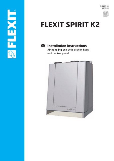
FLEXIT SPIRIT K2<br />
<strong>Installation</strong> <strong>instructions</strong><br />
Air handling unit with kitchen hood<br />
and control panel<br />
111140E-03<br />
2011-08<br />
ART.NO.:<br />
700010<br />
-700017
Contents<br />
<strong>Installation</strong> <strong>instructions</strong> K2R<br />
1 <strong>Installation</strong>/Preliminaries 4<br />
1.1 Inspection/Maintenance 4<br />
1.2 Space Required 4<br />
1.3 Location requirements 4<br />
2 <strong>Installation</strong> of <strong>Flexit</strong> SPIRIT K2 R 6<br />
2.1 Installing the volume hood 6<br />
2.2 Encasing 7<br />
3 Connection of unit and electrical work 8<br />
3.1 Connection of unit 8<br />
3.2 Electrical work 8<br />
3.3 Automatic Control 8<br />
3.4 External components 8<br />
4 Sizes/Physical Dimensions 9<br />
4.1 Dimensioned sketch <strong>Flexit</strong> SPIRIT K2 R 9<br />
5 General Drawings and System Drawings 10<br />
6 Capacity and sound data 11<br />
6.1 Capacity diagram, sound data, specifications - K2 R AC 11<br />
6.2 Capacity diagram, sound data, specifications - K2 R EC 12<br />
7 Technical data 13<br />
7.1 Technical data <strong>Flexit</strong> SPIRIT K2 R 13<br />
8 <strong>Installation</strong> of control panel CI 60/600 14<br />
8.1 Content 14<br />
8.2 <strong>Installation</strong> of CI60/600 14<br />
8.3 Concealed installation 15<br />
8.4 Surface installation 15<br />
8.5 Finishing off – CI60 15<br />
8.6 Finishing off – CI600 15<br />
9 Adjusting EC units 16<br />
9.1 Adjustment with CI60 16<br />
9.2 Adjustment with CI600 17<br />
10 Adjusting AC units 18<br />
11 Adjusting the Kitchen Hood 19<br />
11.1 Forced Ventilation 19<br />
12 Adjustment Curves 19<br />
12.1 Forced ventilation <strong>Flexit</strong> SPIRIT K2 R 19<br />
13 Final checks/first use 20<br />
14 EC Declaration of Conformity 21<br />
Our products are subject to continuous development and we therefore reserve the right to make changes.<br />
We also disclaim liability for any printing errors that may occur.<br />
2
!<br />
Important Safety Instructions:<br />
It is the installer's responsibility to carry out a full safety and function assessment of the appliance<br />
To reduce the risk of fire, electric shock or injury, read all the safety <strong>instructions</strong> and warning texts before<br />
using the appliance.<br />
• This unit is only designed for ventilation air in buildings.<br />
• It must not be used to extract combustible or flammable gases.<br />
• Remove the power plug before commencing any service and maintenance work.<br />
• Before opening the door, current to the unit must be turned off and the fans must have had time to stop (min. 3 mins.).<br />
• The unit contains heating element which must not be touched when it is hot.<br />
• The unit must not be operated without the filters being in place.<br />
• Do not cook substances which could catch fire under the ventilator.<br />
• Do not leave a saucepan or frying pan containing oil or grease unsupervised.<br />
• Follow the <strong>instructions</strong> in the user manual.<br />
To maintain good indoor air quality, comply with regulations and to avoid condensation damage the unit must never be stopped<br />
apart from during service/maintenance or in connection with an accident.<br />
Symbols Used<br />
These products bear a number of symbols used for<br />
labelling the 6 actual product and in installation 5 and user<br />
documentation.<br />
D<br />
C<br />
B<br />
EXAMPLE OF NIPPLE LOCATION<br />
(shown as right-hand model)<br />
A<br />
6<br />
5<br />
<strong>Installation</strong> <strong>instructions</strong> K2R<br />
14,0<br />
4<br />
3<br />
4<br />
!<br />
35,0<br />
3<br />
HIGH VOLTAGE<br />
DANGER! DO NOT TOUCH<br />
CAUTION When a text bears this symbol, it<br />
means that personal injury or serious damage to<br />
the equipment may result if the <strong>instructions</strong> are<br />
not followed.<br />
NB! When a text bears this symbol, damage to<br />
equipment or a poor utilisation ratio may result if<br />
<strong>instructions</strong> are not followed.<br />
According to IEC/EN 60335-1<br />
Adhesiv:<br />
Note that the product is not designed for operation by Permanent person with impaired<br />
physical, motor or mental abilities. The product must also not be used by<br />
persons who lack experience or knowledge, unless they have received guidance<br />
or <strong>instructions</strong> in operating the product safely by a person responsible<br />
for safety.<br />
Date<br />
Drawn Projection Scale<br />
24.03.2009 leif<br />
Status<br />
Approved<br />
2:1<br />
3<br />
Description<br />
Project<br />
SAFETY SWITCH<br />
Type:<br />
Material:<br />
Colour:<br />
Stocknumber<br />
2<br />
Opaque<br />
Glossy vinyl<br />
White<br />
Etikett sikkerhetsbryter<br />
G2-1A<br />
102732<br />
2<br />
Replace
1 <strong>Installation</strong>/Preliminaries<br />
See separate documentation for installation of ducts, valves,<br />
etc.<br />
The unit is designed for indoor installation.<br />
1.1 Inspection/Maintenance<br />
The unit must be installed with space for service and<br />
maintenance such as filter replacement and cleaning the<br />
fans and recovery system.<br />
The control cable with plug for automatic control on top of<br />
the unit must be easily accessible.<br />
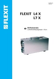
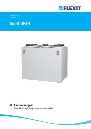
1.2 Space Required<br />
Type A B C<br />
K2 R 335 mm 2 x 2 mm 215-380 mm<br />
A: Space in front of unit<br />
B: Space at side of unit<br />
C: Space above unit<br />
These are minimum requirements and only take service<br />
needs into account. National statutory requirements for<br />
electrical safety may deviate from this. Check which rules<br />
apply in your country.<br />
700mm<br />
(unit)<br />
70mm<br />
(volume hood)<br />
845mm<br />
C=215-380mm<br />
C=215-380mm<br />
Cover on top of unit<br />
(optional extra)<br />
Filter<br />
Filter<br />
A=335mm<br />
A=335mm<br />
<strong>Installation</strong> <strong>instructions</strong> K2R<br />
Fig. 1<br />
4<br />
1.3 Location requirements<br />
The unit has been designed for location in the kitchen over<br />
the cooker as it contains an integrated kitchen hood. The<br />
unit is available in left or right versions<br />
(exhaust air nipple to the left or right), depending on what is<br />
the most favourable in relation to the duct location.<br />
B=2mm B=2mm B=2mm B=2mm<br />
596mm 596mm<br />
(filter)
1.4 Recommended sound attenuation for<br />
wall-mounting<br />
For wall mounting, the (included) wall bracket fixed to the unit<br />
is used.<br />
The unit must not be placed on a wall with rooms on the<br />
other side which are sensitive to noise. The wall must be<br />
sound-insulated. If necessary, use double plasterboards on<br />
the wall.<br />
Interrupted studs must be used.<br />
Fig. 2<br />
min 600 mm<br />
Recommended 500mm*<br />
min 500(650) mm<br />
*min. req. 650mm for gas cookers<br />
Min. req. 450mm<br />
<strong>Installation</strong> <strong>instructions</strong> K2R<br />
5<br />
720 mm<br />
40 mm<br />
steinull<br />
gips<br />
spikerslag
2 <strong>Installation</strong> of <strong>Flexit</strong> SPIRIT K2 R<br />
<strong>Flexit</strong> SPIRIT K2 R is designed for installation in the kitchen<br />
above the cooker, see Fig. 11. The unit is supplied in left and<br />
right-hand versions depending on what suits duct locations<br />
best (Chap. 5.1).<br />
The unit must be wall-hung from a mounting bracket (Fig. 4)<br />
at the top using the enclosed screws. It must also be screwed<br />
to the wall at the bottom edge of the unit. Remove 2 plastic<br />
plugs to access the mounting holes. For secure mounting, it is<br />
necessary to use extra nailing strips (noggins). The location<br />
of these is shown in Fig. 4.<br />
NB! The wall must have good sound insulation, see Chap. 6.4.<br />
The wall must be completely flat behind the ventilation unit.<br />
If the kitchen hood area is tiled, a suitable liner plate must be<br />
mounted behind the unit. The distance between the bottom<br />
of the grease filter and the cooker should be at least 50 cm<br />
for electric cookers and 65 cm for gas cookers. For the<br />
external dimensions of the unit, see the dimensioned drawing<br />
in Chap. 5.1.<br />
2.1 Installing the volume hood<br />
Fig. 3<br />
fixing, top edge<br />
720 mm<br />
Fig. 4<br />
A<br />
40 mm<br />
3<br />
2<br />
1. Mount the two sides.<br />
2. Attach the two angles.<br />
3. Fix the glass profile.<br />
rockwool<br />
steinull<br />
gips gypsum<br />
spikerslag<br />
studs<br />
1<br />
<strong>Installation</strong> <strong>instructions</strong> K2R<br />
fixing lower edge<br />
6<br />
Fig. 5<br />
Fig. 6<br />
B=2mm B=2mm<br />
596 mm<br />
min 600 mm<br />
min 500(650) mm<br />
Recommended<br />
500mm*<br />
*min. req. 650mm for gas cookers<br />
Min. req. 450mm
2.2 Encasing<br />
When encasing ducts above the unit, make sure that the door<br />
leaves do not collide with the encasing above the unit. The<br />
door will move slightly above the top of the unit when it is put<br />
in place. This can be resolved in at least three ways:<br />
1. The casing must not exceed 597 mm width (dimension A).<br />
2. The casing must not be deeper than 270 mm, measured<br />
from the wall on which the unit is installed (dimension B).<br />
Fig. 7<br />
A = max 597mm<br />
B = max 270mm<br />
C = min 30mm<br />
C<br />
<strong>Installation</strong> <strong>instructions</strong> K2R<br />
B A<br />
7<br />
3. The casing must not be deeper than 270 mm, measured<br />
from the wall on which the unit is installed (dimension B).
3 Connection of unit and electrical<br />
work<br />
3.1 Connection of unit<br />
• Ensure that the ducts arrive at the right muff coupling. See<br />
the marking on the unit (top/bottom and behind door).<br />
The symbols are explained on page 3 and the location is<br />
shown in the dimensioned drawing in Chap. 5.<br />
• Pull the duct insulation well up to the unit.<br />
• To avoid condensation, it is very important for the outdoor<br />
air duct and the exhaust air duct to have insulation and a<br />
plastic muff pulled right down to the unit.<br />
NB! Use tape to seal the plastic sleeve to the unit<br />
but do not compress the insulation.<br />
• Lay the outdoor air duct with a slight incline towards the<br />
outdoor air cap so that any water that enters drains out<br />
again.<br />
• If there is a short distance between the unit and the<br />
exhaust point, sound insulation must be installed to ensure<br />
that the requirements for the outdoor sound level are met.<br />
• Ducts must have good sound insulation, particularly above<br />
the unit.<br />
The unit is suppied with a 1.8 m cable with plug.<br />
The cable leaves the top of the unit and is connected to a<br />
230V 50 Hz single-phase earthed power point located within<br />
a convenient distance. The plug must be used as a service<br />
switch.<br />
NB! Make sure the power point for the unit is not boxed in.<br />
See Chap. 13 for fuse sizes.<br />
A low-voltage cable (with connector) leaves the unit for<br />
use on the control panel. It is important to retain easy<br />
access to this plug - in case of any fault or when replacing<br />
the unit.<br />
<strong>Installation</strong> <strong>instructions</strong> K2R<br />
3.2 Electrical work<br />
All electrical work must be carried out by au-<br />
Service<br />
thorised personnel. 1<br />
The unit must be installed with a separate earth<br />
leakage circuit breaker.<br />
8<br />
3.3 Automatic Control<br />
The control pack is included in the unit package. The<br />
low-voltage cable must be laid between the unit and the<br />
switch unit. See separate manual for automatic control<br />
included in pack.<br />
The low-voltage cable must be laid minimum<br />
30 cm from the 230 V cable and in the case of<br />
chased mounting be laid in 20 mm electrical<br />
piping.<br />
3.4 External components<br />
See wiring diagram enclosed with unit.<br />
2
4 Sizes/Physical Dimensions<br />
4.1 Dimensioned sketch <strong>Flexit</strong> SPIRIT K2 R<br />
(Shown as left-hand model)<br />
514<br />
371<br />
227<br />
84<br />
129<br />
<strong>Installation</strong> <strong>instructions</strong> K2R<br />
229<br />
9<br />
(Shown as right-hand model)<br />
514<br />
371<br />
227<br />
84<br />
129<br />
229
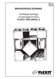
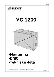
5 General Drawings and System<br />
Drawings<br />
General Diagram (Rotary Wheel-type Heat<br />
Exchanger)<br />
1 (FI2) Extract filter F 7<br />
2 (FI1) Supply air filter F 7<br />
3 (EB1) Heating element<br />
4 (F10-20) Overheating thermostat (heating) (Reset)<br />
5 (M1) Supply air fan<br />
6 (M2) Extract air fan<br />
7 (HR-R) Rotary wheel-type heat exchanger<br />
8 (M4) Rotor motor<br />
9 Control unit<br />
10 Kitchen hood<br />
11 Adjustment switch<br />
12 Damper adjustment<br />
System drawing (electric battery)<br />
B1 Supply air temperature sensor<br />
EB1 Heating element<br />
F10 Overheating thermostat, manual reset<br />
F20 Overheating thermostat, automatic reset<br />
FI1 Supply air filter<br />
FI2 Extract air filter<br />
M1 Supply air fan<br />
M2 Extract air fan<br />
HR-R Rotary wheel-type heat exchanger<br />
M4 Rotor motor<br />
K Kitchen hood<br />
DA4 Damper<br />
<strong>Installation</strong> <strong>instructions</strong> K2R<br />
10<br />
(Shown as left-hand model. The right-hand version is a mirror image.)<br />
3<br />
2<br />
7<br />
8<br />
5<br />
9<br />
FI1<br />
Outdoor Supply Extract Exhaust<br />
air air air air<br />
Outdoor Supply Extract Exhaust<br />
air air air air<br />
M1<br />
B1<br />
EB1<br />
F10<br />
F20<br />
HR-R<br />
K<br />
FI2<br />
M4<br />
DA4<br />
M2<br />
4<br />
1<br />
6<br />
12<br />
11<br />
10
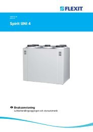
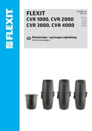
6 Capacity and sound data<br />
6.1 Capacity diagram, sound data, specifications - K2 R AC<br />
Supply air side (with F7 filter)<br />
Contact resistance (Pa)<br />
Pa<br />
400<br />
300<br />
200<br />
100<br />
m 3 /h<br />
l/s 0 20<br />
40 60<br />
80<br />
0<br />
230V<br />
190V<br />
170V<br />
150V<br />
120V<br />
105V<br />
85V<br />
60V<br />
60V<br />
230V<br />
190V<br />
170V<br />
150V<br />
120V<br />
105V<br />
85V<br />
65dB(A)<br />
60dB(A)<br />
55dB(A)<br />
50dB(A)<br />
70dB(A)<br />
0 Air flow rate, 100 m 200<br />
3 /h - Pressure correction factor<br />
Extract air side (with F7 filter)<br />
Contact resistance (Pa)<br />
400<br />
300<br />
200<br />
100<br />
Pa<br />
l/s 0 20<br />
40 60<br />
80<br />
0<br />
m 3 /h<br />
230V<br />
Sound data is given at sound power level LwA in the capacity diagrams<br />
and is corrected with the table below for the various octave bands.<br />
Radiated noise produces Lw in the various octave bands and total<br />
LwA. This is read directly from the supply air table.<br />
Correction factor for<br />
Hz 63 125 250 500 1000 2000 4000 8000 LwA<br />
Supply air 3 2 -2 -5 -5 -6 -13 -29<br />
Extract air 18 14 1 -12 -14 -28 -37 -43<br />
Radiated -46 -39 -29 -36 -40 -44 -54 -58 -33,5<br />
<strong>Installation</strong> <strong>instructions</strong> K2R<br />
11<br />
300<br />
190V<br />
170V<br />
150V<br />
230V<br />
190V<br />
170V<br />
85V<br />
150V<br />
60V<br />
120V<br />
105V<br />
60dB(A)<br />
85V<br />
60V<br />
64dB(A)<br />
55dB(A)<br />
45dB(A) 50dB(A)<br />
120V<br />
105V<br />
0 Air flow rate, 100 m 200<br />
300<br />
3 /h - Pressure correction factor<br />
80<br />
60<br />
40<br />
20<br />
0<br />
80<br />
60<br />
40<br />
20<br />
0<br />
Power consumption in Watt<br />
W<br />
Power consumption in Watt<br />
W<br />
Yellow field: SFP < 1.0 per fan<br />
Yellow field: SFP < 1.0 per fan<br />
Data for supply air is measured in accordance with ISO 5136,<br />
"In-duct method".<br />
Radiated noise is measured in accordance with ISO 9614-2.<br />
Bruel & Kjær measuring equipment, type 2260.<br />
Air capacity at various capacity settings in Volt.<br />
Supply air fan power consumption at various capacity settings.<br />
Sound power level LwA, cf. correction table.
<strong>Installation</strong> <strong>instructions</strong> K2R<br />
6.2 Capacity diagram, sound data, specifications - K2 R EC<br />
Supply air side (with F7 filter)<br />
Contact resistance (Pa)<br />
Pa<br />
m 3 /h<br />
l/s 0 20<br />
40 60<br />
80<br />
400<br />
300<br />
200<br />
100<br />
0<br />
100%<br />
80%<br />
60%<br />
40%<br />
Extract air side (with F7 filter)<br />
Contact resistance (Pa)<br />
Pa<br />
300<br />
100<br />
m 3 /h<br />
200<br />
0<br />
60%<br />
80%<br />
100%<br />
40% 65dB(A)<br />
55dB(A)<br />
60dB(A)<br />
0 100<br />
200<br />
300<br />
Air flow rate, m 3 /h - Pressure correction factor<br />
Sound data is given at sound power level LwA in the capacity diagrams<br />
and is corrected with the table below for the various octave bands.<br />
Radiated noise produces Lw in the various octave bands and total<br />
LwA. This is read directly from the supply air table.<br />
Correction factor for Lw<br />
Hz 63 125 250 500 1000 2000 4000 8000 LwA<br />
Supply air 3 2 -2 -5 -5 -6 -13 -29<br />
Extract air 18 14 1 -12 -14 -28 -37 -43<br />
Radiated -41 -35 -33 -39 -40 -49 -50 -60 -33,5<br />
12<br />
70dB(A)<br />
l/s 0 20 40 60 80<br />
400<br />
100%<br />
80%<br />
60%<br />
40%<br />
80%<br />
100%<br />
60%<br />
60dB(A)<br />
40% 55dB(A)<br />
63dB(A)<br />
45dB(A) 50dB(A)<br />
Air flow rate, m 3 /h - Pressure correction factor<br />
0 100<br />
200<br />
300<br />
80<br />
60<br />
40<br />
20<br />
0<br />
80<br />
60<br />
40<br />
20<br />
0<br />
Power consumption in Watt<br />
W<br />
Power consumption in Watt<br />
W<br />
Yellow field: SFP < 1.0 per fan<br />
Yellow field: SFP < 1.0 per fan<br />
Data for supply air is measured in accordance with ISO 5136,<br />
"In-duct method".<br />
Radiated noise is measured in accordance with ISO 9614-2.<br />
Bruel & Kjær measuring equipment, type 2260.<br />
Air capacity at various capacity settings in %<br />
Supply air fan power consumption at various capacity settings.<br />
Sound power level LwA, cf. correction table.
7 Technical data<br />
7.1 Technical data <strong>Flexit</strong> SPIRIT K2 R<br />
AC EC<br />
Rated voltage 230 V/50 Hz 230 V/50 Hz<br />
Fuse size 10 A 10 A<br />
Rated current, total 3,7 A 3,91 A<br />
Rated power, total 846 W 870 W<br />
Rated power, electric batteries 700 W 700 W<br />
Output fans 2 x 62 W 2 x 74 W<br />
Fan type B-wheel F-wheel<br />
Fan motor control Transformer 0-10 V<br />
Max. fan speed 2,500 RPM 1,970 RPM<br />
Automatic control standard CS 50 CS 50<br />
Filter type (SUP/EXTR) F7/F7 F7/F7<br />
SUP filter dimensions (WxHxD) 130x335x50 mm 130x335x50 mm<br />
EXTR filter dimensions (WxHxD) 130x335x50 mm 130x335x50 mm<br />
Weight 56 kg 56 kg<br />
Duct connection<br />
Duct connection kitchen fan<br />
Dia. 125 mm (sleeve) Dia. 125 mm (sleeve)<br />
Height 700 mm* 700 mm*<br />
Width 598 mm 598 mm<br />
Depth 510 mm** 510 mm**<br />
* without volume hood and duct connection, see Chap. 5<br />
** see Chap. 5<br />
<strong>Installation</strong> <strong>instructions</strong> K2R<br />
13
<strong>Installation</strong> <strong>instructions</strong> K2R<br />
8 <strong>Installation</strong> of control panel CI 60/600<br />
8.1 Content<br />
1. Control panel<br />
2. Back piece for concealed installation<br />
3. Back piece for surface installation<br />
4. <strong>Installation</strong> <strong>instructions</strong><br />
5. Cable for control panel<br />
8.2 <strong>Installation</strong> of CI60/600<br />
!<br />
CAUTION! The control panel must be connected<br />
to the ventilation unit before the ventilation<br />
unit is connected to mains.<br />
Lay the cable for the control panel between the ventilation<br />
unit and the control panel. The control panel is adapted for<br />
concealed installation over a single connection box (use low<br />
back piece, item no. 2) or surface installation on the wall (use<br />
high back piece, item no. 3).<br />
Click the cable into the contact at the back of the control<br />
panel and into the contact on the top of the ventilation unit.<br />
OBS! The low-voltage cable must be at least<br />
30 cm from cables carrying mains voltage or<br />
higher. With concealed installation, the cable is<br />
laid in 20 mm conduit pipes. The cable length must not<br />
exceed 24 meters.<br />
It is possible to connect two CI60 panels and one CI600<br />
panel to each unit. If several CI60 panels are used, each<br />
panel must have its own identity. This is selected with the<br />
switch on the panel’s printed circuit board (se Fig. 27). Use<br />
the appropriate table settings. The panels can be connected<br />
serially, in arbitrary order.<br />
OFF = MASTER<br />
ON = SLAVE<br />
4<br />
14<br />
5<br />
Fig. 8<br />
Configuration<br />
CI 600 (MASTER)<br />
CI60 1 (SLAVE)<br />
CI60 2 (SLAVE)<br />
CI60 1 (MASTER)<br />
CI60 2 (SLAVE)<br />
CI 600 (MASTER)<br />
CI60 (SLAVE)<br />
1<br />
ON OFF<br />
Setting<br />
3<br />
Automatic<br />
OFF<br />
ON<br />
OFF<br />
ON<br />
Automatic<br />
Irrelevant<br />
2
8.3 Concealed installation<br />
Lay the cable between the wall box and the ventilation unit in<br />
the preinstalled conduit pipe. Fit the back piece (item no. 2),<br />
over the wall box and click the cable in directly from behind<br />
as in the illustration (se Fig. 9).<br />
Fig. 9<br />
8.4 Surface installation<br />
Lay the cable between the back piece (item no. 3), and the<br />
ventilation unit. Cut out the perforation in the corner of the<br />
back piece that is suitable for installation. Screw the back<br />
piece to the wall with suitable screws. Click the cable into<br />
the control panel from below, where there is a socket in the<br />
printed circuit board (se Fig. 10).<br />
Fig. 10<br />
<strong>Installation</strong> <strong>instructions</strong> K2R<br />
15<br />
8.5 Finishing off – CI60<br />
Slide the panel off as shown by arrow no. 1 (see Fig. 11) and<br />
fit the control panel straight into the back piece as shown<br />
by arrow no. 2 (see Fig 12) until it clicks into place. Slide the<br />
panel back on.<br />
Fig. 11 Fig. 12<br />
1<br />
8.6 Finishing off – CI600<br />
Fit the control panel over the hooks in the back piece as<br />
shown by arrow no. 1 and then click the panel into place at<br />
the bottom edge as shown by arrow no. 2 (see Fig. 13).<br />
Fig. 13<br />
2<br />
2<br />
1
9 Adjusting EC units<br />
9.1 Adjustment with CI60<br />
The unit's air supply MUST be adjusted before the<br />
unit is used for the first time. This should be done in<br />
accordance with the projection documents. Adjust the<br />
values based on the projected values.<br />
9.1.1 Adjustment<br />
Only stage 2 (NORMAL) needs to be adjusted. Stages 1<br />
and 3 have fixed settings, while stage 2 has to be adjusted as<br />
required in the individual home.<br />
The function of the different stages:<br />
MIN Must not be used when the home is in use.<br />
Must not be used in the first two heating<br />
seasons.<br />
NORMAL Used under normal conditions. On this<br />
setting the air supply must be adjusted<br />
according to current regulations.<br />
MAX Used if there is a need for increased air<br />
supply on account of higher occupancy or<br />
a raised humidity level, for example during<br />
showering or when clothes are being dried.<br />
This setting is normally used for limited<br />
periods.<br />
The ventilation unit's air supply is adjusted in speed level<br />
NORMAL using the knobs on the back of the cover. Knob 9 is<br />
used for supply air level and knob 8 for extract air level (see<br />
Fig. 14). The adjustment range is 20-100% of the maximum<br />
level according to the scale on the knob.<br />
Factory settings for supply air/extract air:<br />
MIN 50% (fixed)<br />
NORMAL 75% (variable)<br />
MAX 100% (fixed)<br />
9.1.2. Adjusting the temperature<br />
The temperature required for the supply air can be set<br />
with knob 11. The adjustment range is 10 - 30°C. It should<br />
normally be set to around 18°C. Use of the factory setting is<br />
recommended.<br />
If necessary, the ventilation unit's additional heating can<br />
also be switched ON/OFF with switch 10. In this case only<br />
the rotating heat exchanger is used as a source of heat. It is<br />
best to leave it in ON position, as the unit will then respond<br />
automatically when there is a need for additional heating.<br />
<strong>Installation</strong> Instructions K2R<br />
16<br />
Fig. 14<br />
9<br />
8<br />
10 11
REGULATION START MENU TYPE<br />
COOLING LANGUAGE<br />
NEUTRAL TIME<br />
LANGUAGE ZONE AND DATE<br />
EXT. TEMP. CONTROL<br />
MAIN<br />
TIME AND<br />
MENU<br />
DATE<br />
MAIN MENU<br />
START MENU<br />
><br />
SUPPLY MAIN AIR MENU<br />
> OK?<br />
EXTRACT AIR MIN<br />
OK? OK?<br />
><br />
TIMER NORMAL<br />
MIN<br />
> ><br />
AIR VOLUME MAX<br />
NORMAL COMP<br />
><br />
MAX<br />
MAX<br />
<strong>Installation</strong> <strong>instructions</strong> K2R<br />
TIMER<br />
MAIN MENU MAX TIMER<br />
><br />
><br />
OK?<br />
OK? ><br />
OK?<br />
SEN TEM<br />
FIRE<br />
COM<br />
STAR<br />
REST<br />
TEMPERA<br />
LANGUAGE<br />
OK?<br />
MIN<br />
TIME AND DATE<br />
><br />
MAIN MENU<br />
><br />
9.2 Adjustment with CI600<br />
TEMPERATURE REGULATION<br />
The unit's air START supply UP MUST MENUbe<br />
adjusted before<br />
the unit is used START for UP the MENU first time. This should<br />
NORMAL<br />
MAX SETTINGS<br />
OK?<br />
><br />
SETTINGS<br />
><br />
MAX TIMER<br />
This dialog is identical<br />
FAN REGULATION<br />
for the supply air and extract air fans.<br />
MAIN MENU 2<br />
The fans are adjusted MAIN MENU individually 2 to the desired capacity for<br />
18<br />
be done in accordance with the projection<br />
documents. Adjust the values based on the projected<br />
the respective speed.<br />
SETTINGS<br />
><br />
HEATING<br />
values. REGULATION TYPE<br />
START UP MENU<br />
REGULATION<br />
EXTR OK?<br />
9.2.1 Adjustment MAX SUPPLY AIR TEMP<br />
35°<br />
MIN SUPPLY AIR TEMP<br />
15°<br />
Only stage 2 (NORMAL) needs to be adjusted.<br />
Note that it is also possible to adjusted stages 1 and 3<br />
SUPPLY AIR<br />
MAIN MENU<br />
MIN MAIN SPEED MAIN MENU MENU 2<br />
NORMAL SPEED MIN<br />
MAX SPEEDNORMAL<br />
MIN<br />
MAX<br />
NORMAL<br />
MAX<br />
MAX<br />
TIMER<br />
MAIN MENU MAX TIMER<br />
50%<br />
75%<br />
100%<br />
OK?<br />
OK?<br />
OK?<br />
SEN<br />
HE<br />
SUP HE<br />
EXT<br />
OUT HEA<br />
RETU HEA<br />
FILT<br />
HEATING<br />
with a CI600 control panel. This should only be done if a<br />
MIN<br />
special need arises, however. This is because it is extremely<br />
important to have adequate air flow rates.<br />
The function of REGULATION the different stages: TYPE 1<br />
MIN Must not be used when the home is in use. Must<br />
not be used in the first two heating seasons.<br />
NORMAL Used under normal conditions. On this setting<br />
NORMAL<br />
MAX SETTINGS<br />
OK?<br />
><br />
SETTINGS<br />
><br />
Factory MAX settings TIMERfor<br />
supply air/extract air:<br />
INLET AIR<br />
MIN MAIN 50% MENU (variable) 2<br />
MAIN MENU 2<br />
NORMAL 75% (variable)<br />
SETTINGS<br />
><br />
MAX 100% (variable)<br />
HEATING EL<br />
MAX<br />
REGULATION the air supply TYPE must be adjusted according to<br />
current regulations.<br />
REGULATION<br />
SUPPL OK?<br />
Used if there is a need for increased air supply<br />
on account of higher occupancy or a raised<br />
humidity level, for example during showering<br />
EXTRACT AIR<br />
9.2.2 MIN MAIN SPEED Temperature<br />
MENU 2<br />
regulation 50% OK?<br />
NORMAL SPEED<br />
75%<br />
In this MAX menu SPEEDscreen<br />
(located under 100% "Advanced user") you<br />
configure the temperature regulation and cooling functions.<br />
SU<br />
CAL<br />
or when clothes are being dried. This setting is<br />
PIN normally CODE used for limited periods.<br />
PIN CODE<br />
TEMPERATURE REGULATION<br />
TEMPERATURE REGULATION<br />
FA<br />
FA<br />
First go to the "Advanced user" menu, enter the PIN and<br />
press OK:<br />
PIN CODE<br />
0 0 0 0<br />
0 0 0 0<br />
0 0 0 0<br />
COOLING<br />
COOLING<br />
MIN OUTDOOR TEMP<br />
MIN SPEED<br />
RESTART DELAY<br />
COOLNESS RECOVERY<br />
REGULATION TYPE 2<br />
PIN CODE<br />
PIN CODE<br />
OK?<br />
Then go to ADVANCED the "Fan PIN control" CODE<br />
USER<br />
ADVANCED USER<br />
menu. The fans are selected and<br />
configured in TEMPERATURE this menu screen. REGULATION Then go to > adjustment of<br />
the extract air TEMPERATURE fan and supply REGULATION air fan. ><br />
FAN REGULATION<br />
CONFIGURATION<br />
FAN REGULATION<br />
FAN REGULATION OPERATING CONFIGURATION TIME<br />
ADVANCED FACTORY OPERATING<br />
USERSETTINGS<br />
TIME<br />
SUPPLY AIR SERVICE FACTORY SETTINGS<br />
EXTRACT TEMPERATURE AIRSERVICE<br />
REGULATION<br />
TIMER FAN REGULATION<br />
AIR VOLUME CONFIGURATION COMP<br />
OPERATING TIME<br />
FACTORY SETTINGS<br />
SERVICE<br />
COOLNESS RECOVERY<br />
DIFF<br />
KJØLING<br />
><br />
><br />
> OK?<br />
OK? ><br />
><br />
><br />
><br />
OFF<br />
1°<br />
COOLNESS RECOVERY<br />
ADVANCED USER<br />
ADVANCED USER<br />
OPERATING<br />
FAN REGULATION<br />
ADVANCED INFORMATION USER<br />
OPERATING INFORMATION<br />
AV<br />
18°<br />
MIN<br />
180 s<br />
OK?<br />
OK?<br />
OK?<br />
><br />
OK?<br />
> OK?<br />
><br />
><br />
><br />
><br />
OK?<br />
17<br />
REGULATION TYPE<br />
COOLING REGULATION TYPE<br />
NEUTRAL COOLING ZONE<br />
EXT. NEUTRAL TEMP. ZONE CONTROL<br />
EXT. TEMP. CONTROL<br />
TEMPERATURE REGULATION EXTRACT AIR<br />
REGULATION TYPE<br />
COOLING<br />
NEUTRAL ZONE<br />
EXT. TEMP. CONTROL<br />
><br />
><br />
OK?<br />
><br />
REGULATION TYPE<br />
TEMPERATURE REGULATION TYPE REGULATION<br />
REGULATION<br />
MAX REGULATION SUPPLY AIR TEMP<br />
MIN MAX SUPPLY AIR TEMP<br />
MIN SUPPLY AIR TEMP<br />
REGULATION TYPE<br />
REGULATION<br />
MAX SUPPLY AIR TEMP<br />
MIN SUPPLY AIR TEMP<br />
TIMER<br />
REGULATION TYPE<br />
REGULATION TYPE<br />
1<br />
EXTR OK?<br />
35°<br />
15°<br />
AIR VOLUME COMPENSATION<br />
SUPPLY AIR REGULATION TYPE MAX 1<br />
REGULATION TYPE 1<br />
EXTRACT AIR<br />
MIN<br />
><br />
><br />
OK? ><br />
> OK?<br />
><br />
TIMER<br />
Regulation STANDARD TEMPERATURE type SPEED REGULATION MAX OK?<br />
If supply STANDARD TEMPERATURE<br />
air regulation TIME is<br />
REGULATION<br />
selected, 30 mno<br />
further settings can<br />
be set here. If extract air regulation is selected, the max. and<br />
min. supply air temperatures can also be specified.<br />
EXTR OK?<br />
35° EXTR OK?<br />
15° 35°<br />
15°<br />
OK?<br />
SUP<br />
EXT SUP<br />
TIM EXT<br />
AIR TIM<br />
AIR<br />
FAN REG<br />
SUPPLY AIR<br />
EXTRACT A<br />
TIMER<br />
AIR VOLUM<br />
FILT<br />
ACT<br />
SU<br />
SU<br />
MIN<br />
NO MIN<br />
MA NO<br />
MA<br />
SUPPLY A<br />
MIN SPEED<br />
NORMAL SP<br />
MAX SPEED<br />
FIR<br />
MO<br />
EX<br />
EX
10 Adjusting AC units<br />
The unit's air supply MUST be adjusted before<br />
the unit is used for the first time. This should<br />
be done in accordance with the projection<br />
documents. Adjust the values based on the projected<br />
values.<br />
Only stage 2 (NORMAL) needs to be adjusted. Stages 1<br />
and 3 have fixed settings, while stage 2 has to be adjusted as<br />
required in the individual home.<br />
The function of the different stages:<br />
MIN Must not be used when the home is in use.<br />
Must not be used in the first two heating<br />
seasons.<br />
NORMAL Used under normal conditions. On this<br />
setting the air supply must be adjusted<br />
according to current regulations.<br />
MAX Used if there is a need for increased air<br />
supply on account of higher occupancy or<br />
a raised humidity level, for example during<br />
showering or when clothes are being dried.<br />
This setting is normally used for limited<br />
periods.<br />
Unlike units with EC fans, AC models are adjusted using<br />
switches in the electrical compartment (see Figure 15).<br />
Adjusting parameters on the CI60 or CI600 control panel will<br />
not affect fan speeds on a unit with AC fans.<br />
It is possible to access a wide range of voltages by moving<br />
the cable set's contacts on the transformer and so adjust<br />
the air flow rate for stage 2.<br />
Supply air/extract air setting:<br />
MIN 85 V<br />
105 V (only available by making change on<br />
transformer)<br />
NORMAL 120 V<br />
150 V (factory setting)<br />
170 V<br />
190 V (only available by making change on<br />
transformer)<br />
MAX 230 V<br />
<strong>Installation</strong> Instructions K2R<br />
18<br />
Fig. 15<br />
SUPPLY AIR<br />
EXTRACT AIR
3<br />
11 Adjusting the Kitchen Hood<br />
If basic ventilation is desired via the kitchen hood, the<br />
damper from the factory must be replaced. Replace it with a<br />
damper with adjustment options. This is not supplied with the<br />
unit.<br />
Fig. 16<br />
11.1 Forced Ventilation<br />
B ( 1 : 1 )<br />
The unit has 4 forced ventilation options:<br />
1. (Switch on front of unit.) This gives a half-open damper<br />
which will increase the air volume passing through the hood.<br />
2. Turn the knob to position 2. This gives a fully open<br />
damper which will allow even more air through the kitchen<br />
hood.<br />
3. Turn the knob to position 3. This will give a fully-open<br />
damper which will allow even more air through the kitchen<br />
hood, in that the fans go to speed 3.<br />
4. The air volume through the unit can also be increased by<br />
setting the fans to speed 3 via the control panel (external<br />
panel). See separate <strong>instructions</strong>.<br />
Date<br />
Drawn Projection Scale<br />
18.02.2009 The damper needs closing leifagain<br />
manually. There is no timer<br />
Status in the damper. Closed Approved in position O.<br />
Description The air entering the unit through the kitchen hood does not<br />
pass through the rotary heat exchanger (by-pass).<br />
Project<br />
Stocknumber<br />
G2-1A<br />
0<br />
1<br />
2<br />
<strong>Installation</strong> <strong>instructions</strong> K2R<br />
2<br />
3<br />
1:5<br />
19<br />
12 Adjustment Curves<br />
12.1 Forced ventilation <strong>Flexit</strong> SPIRIT K2 R<br />
Max. air volume through kitchen hood in case of forced<br />
air volume<br />
Measurements have been taken at 2/3 pressure in the<br />
extract air duct and 1/3 pressure in the exhaust air duct<br />
before opening the damper.<br />
Replaces: Replaced by:<br />
351600<br />
1<br />
C<br />
B<br />
A
13 Final checks/first use<br />
13.1 Final Checks<br />
Check that:<br />
• The duct insulation is in accordance with the manual<br />
and the technical documents. It is very important the<br />
ducts from the unit are also effectively insulated so that<br />
no condensation forms on or in the ducts. It is especially<br />
important to check this if the ducts are to be boxed in.<br />
• Ducts are connected to the right nipples – check against<br />
the unit drawings below.<br />
• Adjustments have been made in accordance with the<br />
manual and project planning documents (documentation<br />
of ventilation data).<br />
• The unit operates normally at all stages.<br />
• Heating switches in.<br />
• The unit has filters for both outdoor air and extract air.<br />
• Tumble dryers must not be connected to the unit.<br />
The installer may be held liable for any incorrect<br />
or defective installation.<br />
<strong>Flexit</strong> SPIRIT K2 R, Left-hand model<br />
<strong>Installation</strong> <strong>instructions</strong> K2R<br />
20<br />
13.2 First use<br />
• Check that the control panel has been connected.<br />
• Plug the unit into the mains supply.<br />
• The unit will now start.<br />
• The unit will automatically perform a start-up procedure<br />
lasting approx. 2 min.<br />
• After the start-up procedure the unit will follow the settings<br />
entered on the control panel.<br />
• If it is wished to check or alter the settings, this can be<br />
done from the control panel.<br />
(See separate documentation for automatic control.)<br />
<strong>Flexit</strong> SPIRIT K2 R, Right-hand model
14 EC Declaration of Conformity<br />
This declaration confirms that the products meet the<br />
requirements in the following Council Directives and<br />
standards:<br />
2004/108/EF Electromagnetic Compatibility (EMC)<br />
2006/95/EF Low-voltage Directive (LVD)<br />
98/37/EEC Machine Directive (Safety)<br />
Manufacturer: FLEXIT AS, Televeien 15, 1870<br />
Ørje, Norway<br />
Type: K2 R Ventilation unit<br />
Conforms to following standards:<br />
Safety standard EN 60335-1:2002<br />
EMF standard: EN 50366:2003<br />
EMC standard: EN 55014-1.2000<br />
EN 61000-3-2:2000<br />
EN 61000-3-3:1995<br />
EN 55014-2:2:1997<br />
The product has been CE-marked: 2011<br />
FLEXIT AS 16.02.2011<br />
Frank Petersen<br />
CEO<br />
The right to give notice of lack of conformity applies to this product in<br />
accordance with the existing terms of sale, provided that the product is used<br />
and maintained correctly. Filters are consumables.<br />
The symbol on the product shows that this product must not be<br />
treated as household waste. It must be taken to a reception station<br />
for recycling of electric and electronic equipment.<br />
By ensuring the correct disposal of the equipment, you will contribute<br />
to preventing the negative consequences for the environment and<br />
health that incorrect handling may entail. For further information<br />
on recycling of this product, please contact your local authority, your refuse<br />
collection company or the company from which you purchased it.<br />
Notice of lack of conformity as a result of incorrect or defective installation must<br />
be submitted to the installation company responsible. The right to give notice of<br />
lack of conformity may lapse if the system is used incorrectly or maintenance is<br />
grossly neglected.<br />
<strong>Installation</strong> Instructions K2R<br />
21
a<br />
22
<strong>Flexit</strong> AS, Televeien 15, 1870 Ørje, Norway www.flexit.com