6DF Series - Sensors Tecnics, Honeywell
6DF Series - Sensors Tecnics, Honeywell
6DF Series - Sensors Tecnics, Honeywell

You also want an ePaper? Increase the reach of your titles
YUMPU automatically turns print PDFs into web optimized ePapers that Google loves.
NOTICE: This is a Sneak Peek of a new product that is scheduled to be introduced to<br />
general sales in 2012. This document contains preliminary specifications that are subject to<br />
change. To obtain a product sample, please contact Chris Gottlieb at +1 763-954-6311 or<br />
chris.gottlieb@honeywell.com.<br />
<strong>6DF</strong> <strong>Series</strong><br />
6 Degree of Freedom<br />
Inertial Measurement<br />
Unit, 6-D Motion Variant<br />
Durable. Accurate. Eases Integration.<br />
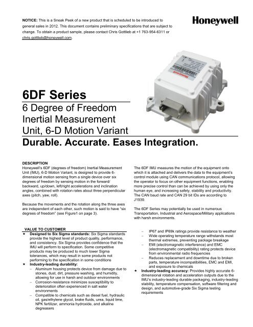
DESCRIPTION<br />
<strong>Honeywell</strong>’s <strong>6DF</strong> (degrees of freedom) Inertial Measurement<br />
Unit (IMU), 6-D Motion Variant, is designed to provide 6-<br />
dimensional motion sensing from a single device over six<br />
degrees of freedom by sensing motion in the forward/<br />
backward, up/down, left/right accelerations and inclination<br />
angles, combined with rotation rates about three perpendicular<br />
axes (pitch, yaw, roll).<br />
Because the movements and the rotation along the three axes<br />
are independent of each other, such motion is said to have “six<br />
degrees of freedom” (see Figure1 on page 3).<br />
The <strong>6DF</strong> IMU measures the motion of the equipment onto<br />
which it is attached and delivers the data to the equipment’s<br />
control module using CAN communications protocol, allowing<br />
the operator to focus on other equipment functions, enabling<br />
more precise control than can be achieved by using only the<br />
human eye, and increasing safety, stability and productivity.<br />
The CAN baud rate and CAN 29 bit IDs are according to<br />
J1939.<br />
The <strong>6DF</strong> <strong>Series</strong> may potentially be used in numerous<br />
Transportation, Industrial and Aerospace/Military applications<br />
with harsh environments.<br />
VALUE TO CUSTOMER<br />
Designed to Six Sigma standards: Six Sigma standards<br />
provide the highest level of product quality, performance,<br />
and consistency. Six Sigma provides confidence that the<br />
IMU will perform to specification. Some competitive<br />
products may be produced to much lower Sigma<br />
tolerances, which may result in some products not<br />
performing to the specification in some conditions<br />
Industry-leading durability:<br />
Aluminum housing protects device from damage due to<br />
stones, dust, dirt, pressure washing, and humidity,<br />
allowing for use in harsh and outdoor environments<br />
Corrosion-resistance minimizes susceptibility to<br />
deterioration often experienced in salt water<br />
environments<br />
Compatible to chemicals such as diesel fuel, hydraulic<br />
oil, gas/ethylene glycol, brake fluids, urea, liquid lime,<br />
NPK fertilizer, ammonia hydroxide, and alkaline<br />
degreasers<br />
IP67 and IP69k ratings provide resistance to weather<br />
Wide operating temperature range withstands most<br />
thermal extremes, preventing package breakage<br />
EMI (electromagnetic interference) and EMC<br />
(electromagnetic compatibility) rating protects device<br />
from environmental radio frequencies<br />
Reduces replacement and downtime due to broken<br />
parts, temperature incompatibilities, EMC and EMI,<br />
and exposure to chemicals<br />
Industry-leading accuracy: Provides highly accurate 6-<br />
dimensional rotation and acceleration outputs due to the<br />
IMU’s industry-leading durable packaging, industry-leading<br />
stability, temperature compensation, software filtering and<br />
design, and automotive-grade Six Sigma testing<br />
requirements
<strong>6DF</strong> <strong>Series</strong><br />
<br />
<br />
<br />
<br />
Eases integration<br />
SAEJ1939 CAN 29 bit identifier communication<br />
output—the standard for the Transportation segment—<br />
allows more data to be transmitted than RS-485 output<br />
IP67 and IP69k ratings minimizes the customer having<br />
to design a weather resistant packaging around the<br />
IMU, allowing for a wide range of use in the application<br />
Wide voltage range (7 V to 32 V) minimizes the need<br />
for a voltage converter<br />
Deutsch connector, common in Transportation<br />
applications, simplifies the customer’s supply chain<br />
and reduces design complexity<br />
Chemical compatibility minimizes the OEM having to<br />
expose the device to the substances<br />
6-dimensional motion sensing: Senses 3-D motion in<br />
the forward/backward, up/down, and left/right<br />
accelerations combined with rotation about three<br />
perpendicular axes (pitch, yaw, roll):<br />
Provides key equipment operating data for automated<br />
steering and control<br />
Frees the operator to focus on equipment functions<br />
Enables precise control which otherwise cannot be<br />
achieved with the human eye alone<br />
Increase accuracy<br />
Increases safety<br />
Increases stability<br />
Increases operator productivity<br />
Industry-leading voltage input flexibility (7 V to 32 V):<br />
Allows customers with multiple product lines the ability<br />
to purchase only one catalog listing instead of multiple<br />
listings<br />
Allows the IMU to accommodate voltage fluctuation<br />
within the vehicle/device<br />
Provides reverse polarity protection in case the end<br />
customer accidentally reverses the red and black<br />
battery voltage wires<br />
Industry-leading application expertise: <strong>Honeywell</strong>’s<br />
application engineers are available to provide assistance<br />
to customers to help troubleshoot unforeseen<br />
communication protocol data, helping to optimize the<br />
customers’ system performance; additionally, <strong>Honeywell</strong>’s<br />
application engineers are available to answer design<br />
questions during the development, launch, and production<br />
of the customer’s product<br />
Industry-leading customization: For Transportationapplications<br />
with high volumes over 500 units per year,<br />
<strong>Honeywell</strong> will consider offering customers a choice of any<br />
CAN protocol, acceleration range up to ±6 g, rotation rates<br />
up to ±75 /s, inclination angles up to ±50 and a sensor<br />
update rate from 1 Hz to 100 Hz:<br />
Allows customers to customize the IMU so that it<br />
readily fits into existing vehicle protocol architecture<br />
Allows customers the ability to make custom protocol<br />
inclusions into the IMU quickly and easily<br />
Allows fast customer development turnaround with<br />
expert engineering support<br />
No customization for Aerospace and Military ITARapplicable<br />
applications<br />
<br />
<br />
Automotive-grade qualified: Certified to operate in<br />
automotive-grade environments due to:<br />
Temperature compensated to operate from -40 °C to<br />
85 °C [-40 °F to 185 °F]<br />
Meets EMC (electromagnetic compatibility) and EMI<br />
(electromagnetic interference) requirements<br />
Meets ESD (electrostatic discharge) requirements<br />
Chemical compatibility (e.g., diesel, hydraulic oil,<br />
gas/ethylene glycol, brake fluid, urea, liquid lime, NPK<br />
fertilizer, ammonia hydroxide, and alkaline degreaser)<br />
Industry-leading temperature performance: A<br />
temperature sensor is placed within each rotation rate<br />
sensor within the IMU:<br />
Provides a temperature value to the processing<br />
module where the data samples are filtered and<br />
compensated<br />
Allows the customer’s system to perform over a wide<br />
temperature range<br />
Long-term stability: Even after long-term use and<br />
thermal extremes, these sensors offer customers<br />
enhanced long-term stability:<br />
Minimizes system calibration needs<br />
Maximizes system performance<br />
Helps support system uptime by eliminating the need<br />
to service or replace the sensor during its application<br />
life<br />
FEATURES AND BENEFITS<br />
Industry-standard CAN J1939: Provides easy-tointegrate,<br />
cost-effective, high-integrity serial data<br />
communications bus for real-time control applications,<br />
allowing enhanced error detection<br />
Test to mechanical shock, thermal shock, and random<br />
vibration: Provides the customer with durability in tough<br />
environments<br />
POTENTIAL APPLICATIONS<br />
Transportation:<br />
Tractors<br />
Harvesters<br />
Loaders<br />
Graders<br />
Bulldozers<br />
Cranes (special restrictions apply: please contact Chris<br />
Gottlieb, Senior Global Product Marketing Manager at<br />
chris.gottlieb@honeywell.com)<br />
Industrial:<br />
Motion/level control (mining conveyors)<br />
Robotics<br />
Shaker tables<br />
Aerospace/Military:<br />
Ground vehicles<br />
UAVs (unmanned aerial vehicle)<br />
2 www.honeywell.com/sensing
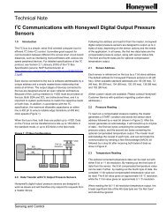
Figure 1. Six Degrees of Freedom<br />
Up<br />
6 Degree of Freedom Inertial Measurement Unit,<br />
6-D Motion Variant<br />
Backward<br />
Roll<br />
Left<br />
Yaw<br />
Right<br />
Pitch<br />
Forward<br />
Down<br />
Translational Movement in<br />
Three Perpendicular Axes<br />
Forward/Backward<br />
Up/Down<br />
Left/Right<br />
Rotational Movement about<br />
Three Perpendicular Axes<br />
Roll<br />
Pitch<br />
Yaw<br />
Table 1. General Specifications<br />
Characteristic Minimum Typical Maximum Unit<br />
Supply voltage 7 32 V<br />
Supply current (at 12 V) 350 mA<br />
Reverse voltage -18 V<br />
Startup time 700 2000 ms<br />
Operating temperature -40 [-40] 85 [185] C [ F]<br />
Storage temperature -40 [-40] 95 [203] C [ F]<br />
Mechanical shock 30 g<br />
Random vibration<br />
3,2 g RMS max. (10 Hz to 2000 Hz), 3 orthogonal plane at 32 hr/axis<br />
Thermal shock<br />
-40 C to 105 C [-40 F to 221 F] soak time, 30 min; transfer time less than 10 s, 30 cycles<br />
Humidity 95 %RH at 25 C to 55 C [77 F to 131 F]<br />
Salt spray 5% salt solution, 96 hr at 35 C [95 F]<br />
Chemical compatibility<br />
diesel fuel, hydraulic oil, ethylene glycol, motor oil, brake fluid, urea nitrogen, liquid lime, NPK<br />
fertilizer, ammonia hydroxide, alkaline degreaser<br />
Sealing IP67, IP69K 1<br />
EMI/EMC:<br />
Emission<br />
Immunity<br />
ESD<br />
Can bus standard<br />
Note 1: Paint peel during IPX9K testing is not considered as failure.<br />
CISPR 25, ISO13766<br />
ISO114252-2 (100 V/m at 200 MHz to 1 GHz, 50 V/m at 1 GHz to 2 GHz)<br />
ISO114252-5 (100 V/m at 10 kHz to 1 MHz)<br />
ISO114252-4 (100 mA at 1 MHz to 400 MHz)<br />
SAE J1113.13 (Nov 2004), 8 kV direct/15 kV air discharge<br />
CAN-29 bits<br />
<strong>Honeywell</strong> Sensing and Control 3
<strong>6DF</strong> <strong>Series</strong><br />
Table 2. Installation Information<br />
Characteristic<br />
Description<br />
Mating connector<br />
Deutsch DT01-12S<br />
Sealing plug<br />
Deutsch 114017 (for unused connector terminations)<br />
Weight<br />
675 g<br />
Heading direction +X<br />
Mounting direction +Z<br />
Mounting bolt<br />
M6X1 socket head cap stainless steel, length 20 mm min., torque 8 N m to 10 N m<br />
Table 3. Sensor Specifications<br />
3-Axis Rotational Rate (X, Y, Z)<br />
Characteristic <strong>6DF</strong>-1N2-C2-HWL and <strong>6DF</strong>-1N6-C2-HWL Unit<br />
Minimum Typical Maximum<br />
Range -75 75 /s<br />
Resolution 1 0.044 /s<br />
Linearity error -1 ±0.25 1 /s<br />
Noise 0.25 0.45 /s (RMS)<br />
Sensitivity error -4 ±1.06 4 %FSS<br />
Offset error 2 -2.5 ±0.5 2.5 /s<br />
Frequency response 22 Hz<br />
G-Sensitivity 3 -0.8 ±0.5 +0.8 /s/g<br />
Noise (pk-pk) 4 -2 ±1.5 2 /s (pk-pk)<br />
2-Axis Inclination (X, Y)<br />
Characteristic <strong>6DF</strong>-1N2-C2-HWL and <strong>6DF</strong>-1N6-C2-HWL Unit<br />
Minimum Typical Maximum<br />
Range -50 50<br />
Resolution 1 0.025<br />
Linearity error -0.2 ±0.1 0.2<br />
Noise 0.2 0.45 (RMS)<br />
Sensitivity error -2 ±1 2 %FSS<br />
Offset error 2 -2 ±0.25 2<br />
Frequency response 30 Hz<br />
3-Axis Acceleration (X, Y, Z) 5<br />
Characteristic <strong>6DF</strong>-1N2-C2-HWL <strong>6DF</strong>-1N6-C2-HWL Unit<br />
Minimum Typical Maximum Minimum Typical Maximum<br />
Range -19.81 19.81 -58.86 58.86 m/s 2<br />
Resolution 1 0.022 0.03 m/s 2<br />
Linearity error -0.392 ±0.05 0.392 -0.687 ±0.05 0.687 m/s 2<br />
Noise 0.2 0.45 0.2 0.45 m/s 2 (RMS)<br />
Sensitivity error -4 ±0.5 4 -3 ±0.5 3 %FSS<br />
Offset error 2 -1 ±0.245 1 -1 ±0.490 1 m/s 2<br />
Frequency response 24 24 Hz<br />
Notes:<br />
1. Resolution refers to sensor resolution and not CAN output resolution.<br />
2. Offset error is measured at relatively zero level or on a flat surface.<br />
3. G-Sensitivity is measured at 25 C [77 F].<br />
4. Pk-pk noise of rotational rate sensor is measured at 0 /s at 25 C [77 F].<br />
5. Accelerometer specification is tested up to ±0.499 g (4.895 m/s 2 ).<br />
4 www.honeywell.com/sensing
6 Degree of Freedom Inertial Measurement Unit,<br />
6-D Motion Variant<br />
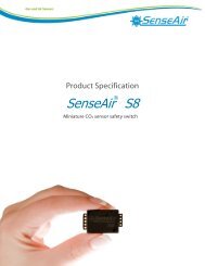
Figure 2. Dimensional Drawing (For reference only: mm/[in])<br />
PIN 7 PIN 12<br />
66,0<br />
[2.60]<br />
13,0<br />
[0.51]<br />
Pinout<br />
Pin 1 = Ground<br />
Pin 2 = CAN low<br />
Pin 11 = CAN high<br />
Pin 12 = Input (Vs)<br />
PIN 6<br />
51,3<br />
[2.02]<br />
81<br />
[3.19]<br />
40,6<br />
[1.60]<br />
116<br />
[4.57]<br />
130<br />
[5.12]<br />
PIN 1<br />
12,4<br />
[0.49]<br />
37,3<br />
[1.47]<br />
26,1<br />
[1.03]<br />
22,3<br />
[0.90]<br />
Recommended Mounting Footprint<br />
48,15<br />
[1.90]<br />
3X M6X1<br />
116<br />
[4.57]<br />
3X 6,40 DIA.<br />
[0.25]<br />
48,15<br />
[1.90]<br />
PART NO.: <strong>6DF</strong>-1N6-C2-HWL<br />
PIN DESIGNATIONS:<br />
1 POWER RETURN<br />
2 CAN LOW<br />
11 CAN HIGH<br />
12 INPUT POWER<br />
96,3<br />
[3.80]<br />
96<br />
[3.78]<br />
135<br />
[5.31]<br />
96,3<br />
[3.79] 3X 22 TYP SENSOR SEATING<br />
[0.87]<br />
1,5<br />
[0.06]<br />
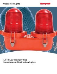
Figure 3. Block Diagram<br />
<strong>6DF</strong> IMU<br />
Processing Module<br />
Customer<br />
System<br />
Sensor Module<br />
3 x Accelerometer<br />
Self Test<br />
Main Processor<br />
Digital Input/<br />
Output<br />
Accelerometers<br />
Rotation Rate<br />
<strong>Sensors</strong><br />
(Gyroscopes)<br />
3 x Rotation Rate<br />
3 x Accelerometer<br />
3 x Status<br />
Analog to<br />
Digital<br />
Converter<br />
3 x Rotation Rate Sensor Self Test<br />
Analog to Digital<br />
Converter<br />
Serial Peripheral<br />
Interface<br />
Digital Input/<br />
Output<br />
CAN A<br />
Reset<br />
Timer<br />
CAN<br />
Tranceiver<br />
Power Supply Module<br />
Reset<br />
Watch Dog TImer<br />
CAN Bus<br />
3 x Temperature<br />
Analog to Digital<br />
Converter<br />
Regulated Power<br />
Supply<br />
Supply<br />
Voltage<br />
12 V Power Monitor<br />
Voltage/Current<br />
Protection<br />
Power to All Modules<br />
<strong>Honeywell</strong> Sensing and Control 5
<strong>6DF</strong> <strong>Series</strong><br />
CAN MESSAGES<br />
Table 4. Messages Transmitted from the IMU to the Host in the Base Software Build<br />
CAN Message Message Identifier Data Length Description<br />
Sensor data (lateral acceleration and<br />
yaw rate)<br />
0xCFF955C 8 bytes IMU to system<br />
Sensor data (longitudinal acceleration<br />
and roll rate)<br />
0xCFF965C 8 bytes IMU to system<br />
Sensor data (vertical acceleration and<br />
pitch rate)<br />
0xCFF975C 8 bytes IMU to system<br />
Sensor data (roll angle and pitch angle) 0xCFF985C 8 bytes IMU to system<br />
Serial number, SW version no.,<br />
0xCFF9E5C<br />
IMU to system<br />
8 bytes<br />
HW version no.<br />
(remote frame)<br />
(on request)<br />
Error status<br />
0xCFF9F5C<br />
(remote frame)<br />
Table 5. IMU to System (Yaw Rate and Lateral Acceleration Definition)<br />
8 bytes<br />
IMU to system<br />
(on request)<br />
Message 0xCFF955C Bits Start Bit Position Description<br />
Rolling counter 8 0 increments the counter for every message sent; rolls<br />
from 255 to 0<br />
Signal state for lateral acceleration 2 8 indicates if lateral acceleration data is valid<br />
Signal state for yaw rate 2 10 indicates if yaw rate data is valid<br />
Signal state for temperature 2 12 indicates if temperature data is valid<br />
Vehicle dynamic lateral acceleration 16 16 digital filtered lateral acceleration signal<br />
Vehicle dynamic yaw rate 16 32 digitally filtered yaw rate signal<br />
Module temperature 8 48 module temperature<br />
10 14-15, 56-63<br />
Table 6. IMU to System (Roll Rate and Longitudinal Acceleration Definition)<br />
Message 0xCFF965C Bits Start Bit Position Description<br />
Rolling counter 8 0 increments the counter for every message sent; rolls<br />
from 255 to 0<br />
Signal state for longitudinal acceleration 2 8 indicates if longitudinal acceleration data is valid<br />
Signal state for roll rate 2 10 indicates if roll rate data is valid<br />
Vehicle dynamic longitudinal acceleration 16 16 digital filtered longitudinal acceleration signal<br />
Vehicle dynamic roll rate 16 32 digitally filtered roll rate signal<br />
Error information 16 48 error information<br />
4 12-15<br />
Table 7. IMU to System (Pitch Rate and Vertical Acceleration Definition)<br />
Message 0xCFF975C Bits Start Bit Position Description<br />
Rolling counter 8 0 increments the counter for every message sent; rolls<br />
from 255 to 0<br />
Signal state for vertical acceleration 2 8 indicates if vertical acceleration data is valid<br />
Signal state for pitch rate 2 10 indicates if pitch rate data is valid<br />
Vehicle dynamic vertical acceleration 16 16 digital filtered vertical acceleration signal<br />
Vehicle dynamic pitch rate 16 32 digitally filtered pitch rate signal<br />
20 12-15, 48-63<br />
6 www.honeywell.com/sensing
6 Degree of Freedom Inertial Measurement Unit,<br />
Table 8. IMU to System (Roll and Pitch Inclination Angle Definition)<br />
6-D Motion Variant<br />
Message 0xCFF985C Bits Start Bit Position Description<br />
Rolling counter 8 0 increments the counter for every message sent; rolls<br />
from 255 to 0<br />
Signal state for roll inclination angle 2 8 indicates if roll Inclination angle data is valid<br />
Signal state for pitch inclination angle 2 10 indicates if pitch Inclination angle data is valid<br />
Vehicle dynamic roll Inclination angle 16 16 digital filtered roll Inclination angle signal<br />
Vehicle dynamic pitch Inclination angle 16 32 digitally filtered pitch Inclination angle signal<br />
2 12-15, 48-63<br />
Table 9. IMU to System (Serial Number Definition) 1<br />
Message 0xCFF9E5C Bits Start Bit Position Description<br />
Module serial number 24 0 module serial number<br />
Software version 8 24 software version<br />
Production date 16 32 software release year, week<br />
16 48-63<br />
Note 1: This message can be requested by transmitting a message with ID 0xCFF9E5C and RTR bit set, to the IMU.<br />
Table 10. IMU CAN Resolution<br />
Number of bits Numerical format Resolution Measurement<br />
Range<br />
Vehicle Dynamic Rates<br />
16 unsigned value 0.0078125 /s<br />
Vehicle Dynamic Accelerations (6 g)<br />
Value Range<br />
(hex)<br />
75 70xA57F<br />
0 0x7FFF<br />
-75 0x5A7F<br />
16 unsigned value 0.01 m/s 2 0 0x7FFF<br />
58.86 0x96FD<br />
-58.86 0x6901<br />
Vehicle Dynamic Accelerations (2 g)<br />
16 unsigned value 0.01 m/s 2 0 0x7FFF<br />
19.62 0x87A9<br />
-19.62 0x7855<br />
Inclination Angles<br />
50 0xE1A7<br />
16 unsigned value 0.002<br />
0 0x7FFF<br />
-50 0x1E57<br />
Table 11. IMU System (Error Information – ID 0xCFF965C)<br />
Number of Bits Start Bit Position Position Error Description<br />
12 48 reserved<br />
1 60 software error<br />
1 61 SPI<br />
1 62 ADC<br />
1 63 IIC<br />
<strong>Honeywell</strong> Sensing and Control 7
Order Guide<br />
Catalog LIsting<br />
<strong>6DF</strong>-1N2-C2-HWL<br />
<strong>6DF</strong>-1N6-C2-HWL<br />
Description<br />
<strong>6DF</strong> <strong>Series</strong> Inertial Measurement Unit, 6-D Motion Variant, 2 g accelerometer<br />
<strong>6DF</strong> <strong>Series</strong> Inertial Measurement Unit, 6-D Motion Variant, 6 g accelerometer<br />
NOTICE<br />
EVALUATION PRODUCTS<br />
THESE PRODUCTS ARE PROTOTYPE,<br />
PREPRODUCTION ITEMS THAT HAVE YET TO<br />
COMPLETE ALL PHASES OF PRODUCT RELEASE<br />
TESTING AND ARE FOR CUSTOMER EVALUATION<br />
ONLY.<br />
THESE ITEMS ARE SOLD “AS IS” WITH NO WARRANTY,<br />
EXPRESS OR IMPLIED, INCLUDING THAT OF<br />
MERCHANTABILITY AND FITNESS FOR A PARTICULAR<br />
PURPOSE.<br />
IN NO EVENT WILL HONEYWELL BE LIABLE FOR ANY<br />
CONSEQUENTIAL, SPECIAL OR INDIRECT DAMAGES.<br />
WARNING<br />
PERSONAL INJURY<br />
DO NOT USE these products as safety or emergency stop<br />
devices or in any other application where failure of the<br />
product could result in personal injury.<br />
Failure to comply with these instructions could result<br />
in death or serious injury.<br />
WARNING<br />
MISUSE OF DOCUMENTATION<br />
The information presented in this product sheet is for<br />
reference only. Do not use this document as a product<br />
installation guide.<br />
Complete installation, operation, and maintenance<br />
information is provided in the instructions supplied with<br />
each product.<br />
Failure to comply with these instructions could result in<br />
death or serious injury.<br />
SALES AND SERVICE<br />
<strong>Honeywell</strong> serves its customers through a worldwide network<br />
of sales offices, representatives and distributors. For<br />
application assistance, current specifications, pricing or name<br />
of the nearest Authorized Distributor, contact your local sales<br />
office or:<br />
E-mail: info.sc@honeywell.com<br />
Internet: www.honeywell.com/sensing<br />
Phone and Fax:<br />
Asia Pacific +65 6355-2828; +65 6445-3033 Fax<br />
Europe +44 (0) 1698 481481; +44 (0) 1698 481676 Fax<br />
Latin America +1-305-805-8188; +1-305-883-8257 Fax<br />
USA/Canada +1-800-537-6945; +1-815-235-6847<br />
+1-815-235-6545 Fax<br />
P r e l i m i n a r y<br />
This publication does not constitute a contract between <strong>Honeywell</strong> and its customers. The contents may be changed at any time<br />
without notice. It is the customer’s responsibility to ensure safe installation and operation of the products. Detailed mounting<br />
drawings of all products illustrated are available upon request.<br />
Sensing and Control<br />
<strong>Honeywell</strong><br />
1985 Douglas Drive North<br />
Golden Valley, Minnesota 55422<br />
www.honeywell.com/sensing<br />
Issue 1<br />
April 2012<br />
Copyright © 2012 <strong>Honeywell</strong> International Inc. All rights reserved.