Mechanical pressure switches - Sensors Tecnics, Honeywell
Mechanical pressure switches - Sensors Tecnics, Honeywell
Mechanical pressure switches - Sensors Tecnics, Honeywell

You also want an ePaper? Increase the reach of your titles
YUMPU automatically turns print PDFs into web optimized ePapers that Google loves.
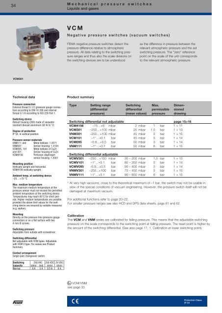
34M e c h a n i c a l p r e s s u r e s w i t c h e sLiquids and gasesV C MN e g a t i v e p r e s s u r e s w i t c h e s ( v a c u u m s w i t c h e s )FEMA negative <strong>pressure</strong> <strong>switches</strong> detect the<strong>pressure</strong> difference relative to atmospheric<strong>pressure</strong>. All data relating to the switching <strong>pressure</strong>ranges and thus also the scale divisions onthe switching devices are to be understoodas the difference in <strong>pressure</strong> between therelevant atmospheric <strong>pressure</strong> and the setswitching <strong>pressure</strong>. The "zero" referencepoint on the scale of the unit correspondsto the relevant atmospheric <strong>pressure</strong>.VCM301Technical dataPressure connectionExternal thread G 1/2 (<strong>pressure</strong> gauge connection)according to DIN 16 288 and internalthread G 1/4 according to ISO 228 Part 1.Switching deviceRobust housing (200) made of seawaterresistantdiecast aluminium GD Al Si 12.Degree of protectionIP 54, in vertical position.Pressure sensor materialsVNM111 and Metal bellows: 1.4571VNM301: Sensor housing: 1.4104VCM095, 101 Metal bellows of CuZnand 301:VCM4156:Sensor housing of CuZnPerbunan diaphragmsensor housing: 1.4301Mounting positionVertically upright and horizontal.VCM4156 vertically upright.Ambient temp. at switching device–25…+70 °CMax. medium temperatureThe maximum medium temperature at the<strong>pressure</strong> sensor must not exceed the permittedambient temperature at the switching device.Temperatures may reach 85°C for short periods.Higher medium temperatures are possibleprovided the above limit values for the switchingdevice are ensured by suitable measures(e.g. siphon).MountingDirectly on the <strong>pressure</strong> line (<strong>pressure</strong> gaugeconnection)or on a flat surface with two4 mm Ø screws.Switching <strong>pressure</strong>Adjustable from outside with screwdriver.Product summaryType Setting range Switching Max. Dimen-(differential differential permissible sioned<strong>pressure</strong>) (mean values) <strong>pressure</strong> drawingSwitching differential not adjustable page 15+16VCM4156 –15…+6 mbar 2 mbar 1 bar 1 + 11VCM301 –250…+100 mbar 25 mbar 1.5 bar 1 + 13VNM301 –250…+100 mbar 45 mbar 3 bar 1 + 15VCM101 –1*…+0.1 bar 45 mbar 3 bar 1 + 14VCM095 –0.9…+0.5 bar 50 mbar 3 bar 1 + 14VNM111 –1*…+0.1 bar 50 mbar 6 bar 1 + 15Switching differential adjustableVCMV301 –250…+100 mbar 30 – 200 mbar 1,5 bar 1 + 13VCMV101 –1*…+0.1 bar 80 – 350 mbar 3 bar 1 + 14VCMV095 –0.9…+0.5 bar 90 – 400 mbar 3 bar 1 + 14VNMV301 –250...+100 bar 70 – 450 mbar 3 bar 1 + 15VNMV111 –1*…+0.1 bar 90 – 650 mbar 6 bar 1 + 15* At very high vacuums, close to the theoretical maximum of –1 bar, the switch may not be usable inview of the special conditions of vacuum engineering. However, the <strong>pressure</strong> switch itself will not bedamaged at maximum vacuum.For additional functions refer to page 20–22.For smaller <strong>pressure</strong> ranges see also HCD and DPS data sheets, page 61 and 62.CalibrationThe VCM and VNM series are calibrated for falling <strong>pressure</strong>. This means that the adjustable switching<strong>pressure</strong> on the scale corresponds to the switching point at falling <strong>pressure</strong>. The reset point is higher bythe amount of the switching differential. (See also page 17, 1. Calibration at lower switching point).Switching differentialNot adjustable with VCM types. Adjustablewith VCM V type. For values see ProductSummary.Contact arrangementSingle-pole changeover switch.Switching 250 VAC 250 VDC 24 VDCcapacity (ohm) (ind) (ohm) (ohm)Normal 8 A 5 A 0.3 A 8 AVCM/VNMsee page 33sProtection Class:IP 54
M e c h a n i c a l p r e s s u r e s w i t c h e sTechnical features/AdvantagesM e c h a n i c a l p r e s s u r e s w i t c h e sT e c h n i c a l f e a t u r e s / A d v a n t a g e sDiecast aluminium housingIP 54 or IP 65version also availableWall mountingor directly on the <strong>pressure</strong> lineSwitching element (microswitch)Lead sealable setpoint adjustmentSetting spindle locking elementTerminal connectionor plug connection toDIN EN175301 Form AStainless steel sensor housingStainless steel bellowswith internal stopPressure connectionG 1/2" externalG 1/4" internalCentring pin9Accessories Solenoid valvesFlow monitors Temperature sensors Thermostats Pressure transmitters Pressure <strong>switches</strong>
10M e c h a n i c a l p r e s s u r e s w i t c h e sDefinitionsD e f i n i t i o n sP r e s s u r e d a t aOver<strong>pressure</strong>VacuumAbsolute <strong>pressure</strong>Pressure over the relevant atmospheric <strong>pressure</strong>. The reference point isatmospheric <strong>pressure</strong>.Pressure under the relevant atmospheric <strong>pressure</strong>. The reference point isatmospheric <strong>pressure</strong>.Over<strong>pressure</strong> relative to absolute vacuum.Differential <strong>pressure</strong> Difference in <strong>pressure</strong> between 2 <strong>pressure</strong> measuring points.Relative <strong>pressure</strong>Over<strong>pressure</strong> or vacuum relative to atmospheric <strong>pressure</strong>.P r e s s u r e d a t a i n a l l F E M A d o c u m e n t s r e f e r s t o r e l a t i v e p r e s s u r e .That is to say, it concerns <strong>pressure</strong> differentials relative to atmospheric <strong>pressure</strong>.Over<strong>pressure</strong>s have a positive sign, vacuums a negative sign.Permissible working <strong>pressure</strong> (maximum permissible <strong>pressure</strong>)The maximum working <strong>pressure</strong> is defined as the upper limit at which the operation, switching reliabilityand water tightness are in no way impaired (for values see Product summary).Bursting <strong>pressure</strong> (test <strong>pressure</strong>)Type-tested products undergo a <strong>pressure</strong> test certified by TÜV affirming that the bursting <strong>pressure</strong>reaches at least the values mentioned in the Product summary. During the <strong>pressure</strong> tests the measuringbellows are permanently deformed, but the pressurized parts do not leak or burst. The bursting <strong>pressure</strong>is usually a multiple of the permissible working <strong>pressure</strong>.Setting rangePressure range in which the cutoff <strong>pressure</strong> can be set with the setting spindle.Pressure unitsUnit bar mbar Pa kPa MPa (psi) Ib/m 21 bar 1 1000 10 5 100 0.1 14.51 mbar 0.001 1 100 0.1 10 -4 0.01451 Pa 10 -5 0.01 1 0.001 10 -6 1.45 · 10 -41 kPa 0,01 10 1000 1 0.001 0,1451 MPa 10 10 4 10 6 1000 1 145In FEMA documents <strong>pressure</strong>s are stated in bar or mbar.Pressure data for a <strong>pressure</strong>switchbased on the exampleof DWR625:Setting range: 0.5-6 barPerm. working <strong>pressure</strong>: 20 barBursting <strong>pressure</strong>: >100 barImportant:All <strong>pressure</strong> data refers to over<strong>pressure</strong>s or vacuums relative to atmospheric <strong>pressure</strong>.Over<strong>pressure</strong>s have a positive sign, vacuums a negative sign.
Maximum <strong>pressure</strong> monitoringRSP = SP – xdMinimum <strong>pressure</strong> monitoringRSP = SP + xdM e c h a n i c a l p r e s s u r e s w i t c h e sDefinitionsD e f i n i t i o n sS w i t c h i n g d i f f e r e n t i a lThe switching differential (hysteresis) is the difference in <strong>pressure</strong> between the switching point (SP)and the reset point (RSP) of a <strong>pressure</strong> switch. Switching differential tolerances occur due to tolerancesin the micro<strong>switches</strong>, springs and <strong>pressure</strong> bellows. Therefore the data in the product summariesalways refers to average values. In the case of limiter functions the switching differential has nosignificance, as one is only interested in the switching point at which cutoff occurs, not the resetpoint. For a controller function, i. e. in the case of <strong>pressure</strong> <strong>switches</strong> used to switch a burner, pumpetc. on and off, a <strong>pressure</strong> switch with an adjustable switching differential should be chosen.The switching frequency of the burner or pump can be varied by changing the switching differential.Adjustable switching differential/ calibrationIn the case of <strong>pressure</strong> <strong>switches</strong> with adjustable switching differential, the hysteresis can be set withinthe specified limits. The switching point (SP) and reset point (RSP) are precisely definable. Whensetting the <strong>pressure</strong> switch, the switching differential situation and the type of factory calibration mustbe taken into account. Some <strong>pressure</strong> <strong>switches</strong> (e.g. minimum <strong>pressure</strong> monitors of the DCM series)are calibrated under "falling" <strong>pressure</strong>, i.e. switching under falling <strong>pressure</strong> takes place at the scalevalue with the switching differential being above it. The device <strong>switches</strong> back at scale value +switching differential. If the <strong>pressure</strong> switch is calibrated under rising <strong>pressure</strong>, switching takes placeat the scale value and the device <strong>switches</strong> back at scale value - switching differential (see direction ofaction). The calibration method is indicated in the data sheets.D i r e c t i o n o f a c t i o nIn principle, any <strong>pressure</strong> switch can be used for both maximum <strong>pressure</strong> and minimum <strong>pressure</strong>monitoring. This excludes <strong>pressure</strong> limiters, whose direction of action (maximum or minimum) ispredefined. The only thing to remember is that the scale reading may deviate by the amount of theswitching differential. See example at bottom left: The scale value is 2.8 bar.Maximum <strong>pressure</strong> monitoringWith rising <strong>pressure</strong>, switching takes place once the preset switching <strong>pressure</strong> is reached (SP).The reset point (RSP) is lower by the amount of the switching differential.Minimum <strong>pressure</strong> monitoringWith falling <strong>pressure</strong>, switching takes place once the preset switching <strong>pressure</strong> is reached (SP).The reset point (RSP) is higher by the amount of the switching differential.Direction of action in vacuum rangeIt is particularly important to define the direction of action in the vacuum range.Rising does not mean a rising vacuum, but rising <strong>pressure</strong> (as viewed from absolute "0"). "Falling"<strong>pressure</strong> means a rising vacuum.For example: Vacuum switch set to -0.6 bar falling means: Switching (SP) takes place under falling<strong>pressure</strong> (rising vacuum) at -0.6 bar. The reset point is higher by the amount of the switching differential(e.g. at -0.55 bar).S e t t i n g a p r e s s u r e s w i t c hTo define the switching point of a <strong>pressure</strong> switch exactly, it is necessary to determine the direction ofaction in addition to the <strong>pressure</strong>. "Rising" means that switching takes place at the set value when the<strong>pressure</strong> rises.The reset point is then lower by the amount of the switching differential. "Falling" means exactly theopposite.Please note when specifying the setting of a <strong>pressure</strong> switch:In addition to the switching point it is also necessary to specify the direction of action (falling or rising).Example for selection of a <strong>pressure</strong> switch:A pump is to be turned on at 2.8 bar and off again at 4.2 bar.Chosen type: DCMV6 according to data sheet DCM. Setting: Scale pointer to 2.8 bar (lower switchingpoint). Switching differential to 1.4 bar (set according to <strong>pressure</strong> gauge).Cutoff point: 2.8 bar +1.4 bar = 4.2 bar.11Accessories Solenoid valvesFlow monitors Temperature sensors Thermostats Pressure transmitters Pressure <strong>switches</strong>
Switch housingPressure connectionSwitching function andconnection scheme(applies only to versionwith microswitch)Switching capacity(for micro<strong>switches</strong> witha silver contact)Mounting positionProtection class(in vertical position)Explosion protectionCodeEC Type ExaminationCertificate NumberElectrical connectionCabel entryAmbient temperatureSwitching pointHysteresisMedium temperatureRelative humidityM e c h a n i c a l p r e s s u r e s w i t c h e sPrincipal technical dataP r i n c i p a l t e c h n i c a l d a t aValid for all <strong>pressure</strong> <strong>switches</strong> of the DCM, VCM, DNM, DA, DWR, DNS and DDCM series that have amicroswitch. The technical data of type-tested units may differ slightly (please refer to particular type sheet).Standard versionPlug connectionTerminal connection…200 …300Diecast aluminium GDAISi 12G 1/2" external thread (<strong>pressure</strong> gauge connection)and G 1/4" internal thread.1/4" internal thread for DDCM differential <strong>pressure</strong><strong>switches</strong>Floating changeover contact.With rising <strong>pressure</strong>single pole switchingfrom 3–1 to 3–2.8 A at 250 VAC5 A at 250 VAC inductive8 A at 24 VDC0.3 A at 250 VDCmin. 10 mA, 12 VDCPreferably vertical (see technical data sheet)IP 54, with terminal connection IP 65–––Plug connection (200 series) orterminal connection (300 series).Pg 11 / for terminal connection M 16 x 1.5–25 to +70 °C (exceptions:DA series –20 to +70 °CDGM and FD series: –25 to +60 °CDCM4016, 4025, 1000, VCM4156: –15 to +60 °C)Adjustable using the setting spindle (for 300 device:after removing switch housing cover)Adjustable or not adjustable (see Product Summary)Max. 70 °C, briefly 85 °C15 to 95 % (non-condensing)version (Ex-d)…70013Diecast aluminium GDAISi 12G 1/2" external thread (<strong>pressure</strong> gauge connection)and G 1/4" internal thread.1/4" internal thread for DDCM differential <strong>pressure</strong><strong>switches</strong>Floating changeover contact.With rising <strong>pressure</strong>single pole switchingfrom 3–1 to 3–23 A at 250 VAC2 A at 250 VAC inductive3 A at 24 VDC0.1 A at 250 VDCmin. 2 mA, 24 VDCVerticalIP 65s 0035 II 2G Ex db eb IIC T6s 0035 II 2D Ex tb IIIC IP65 T85°CPTB 02 ATEX 1121Terminal connectionM 16 x 1.5–20 to +60 °CAdjustable using the setting spindle once the switchhousing cover is removedNot adjustableMax. 60 °C15 to 95 % (non-condensing)Accessories Solenoid valvesFlow monitors Temperature sensors Thermostats Pressure transmitters Pressure <strong>switches</strong>
14M e c h a n i c a l p r e s s u r e s w i t c h e sPrincipal technical dataVacuumHigher medium temperatures are possible provided the above limits for the switching device areensured by suitable measures (e.g. siphon). All <strong>pressure</strong> <strong>switches</strong> can operate under vacuum.This will not damage the device (exception DCM1000).Repetition accuracy ofswitching points< 1% of the working range (for <strong>pressure</strong> ranges > 1 bar).Vibration resistanceNo significant deviations up to 4 g.<strong>Mechanical</strong> durability(<strong>pressure</strong> sensor)With sinusoidal <strong>pressure</strong> application and room temperature, 10 x 10 6 switching cycles.The expected life depends to a very large extent on the type of <strong>pressure</strong> application, therefore thisfigure can serve only as a rough estimate. With pulsating <strong>pressure</strong> or <strong>pressure</strong> impacts in hydraulicsystems, <strong>pressure</strong> surge reduction is recommended.Electrical durability(microswitch)100,000 switching cycles at nominal current 8 A, 250 VAC.A reduced contact load increases the number of possible switching cycles.Isolation valuesOvervoltage category III, contamination class 3, reference surge voltage 4000 V.Conformity to DIN VDE 0110 is confirmed.Oil and grease-freeThe parts of all <strong>pressure</strong> <strong>switches</strong> in contact with the medium are oil and grease-free (exceptthe HCD… and DPS… series). The sensors are hermetically sealed and contain no seals(see also ZF1979, special packing).
1310M e c h a n i c a l p r e s s u r e s w i t c h e sDimensioned drawingsD i m e n s i o n e d d r a w i n g s o f s w i t c h h o u s i n g sHousing 200 (plug connection)Housing 700 (Ex)FORM AD i m e n s i o n e d d r a w i n g s o f p r e s s u r e s e n s o r s211Housing 300 and 500 (terminal connection)15Accessories Solenoid valvesFlow monitors Temperature sensors Thermostats Pressure transmitters Pressure <strong>switches</strong>
16M e c h a n i c a l p r e s s u r e s w i t c h e sDimensioned drawingsD i m e n s i o n e d d r a w i n g s o f p r e s s u r e s e n s o r s121314151619SWDimensioneddrawingSW16 2217 2418 3019 3220 21
18M e c h a n i c a l p r e s s u r e s w i t c h e sPressure switch with locking of switching state (reclosing lockout)Pressure switch with switching statelocking (reclosing lockout)In the case of limiter functions, the switching state must be retained and locked, and only unlocked andthe system restarted once the cause of the safety shutdown has been eliminated. There are two ways ofdoing this:1. <strong>Mechanical</strong> locking inside the <strong>pressure</strong> switchInstead of a microswitch with automatic reset, limiters contain a "bi-stable" microswitch. If the <strong>pressure</strong>reaches the value set on the scale, the microswitch trips over and remains in this position. The lock canbe released by pressing the unlocking button (identified by a red dot on the scale side of the switchingdevice). The lock can operate with rising or falling <strong>pressure</strong>, depending on the version. The device canonly be unlocked when the <strong>pressure</strong> has been reduced (or increased) by the amount of thepredefined switching differential. When selecting a <strong>pressure</strong> limiter, it is necessary to distinguishbetween maximum and minimum <strong>pressure</strong> monitoring. Ex-d versions cannot be equipped with internallocking.Maximum <strong>pressure</strong> limitationSwitching and interlockingwith rising <strong>pressure</strong>.Additional functionZF205.Minimum <strong>pressure</strong> limitationSwitching and interlockingwith falling <strong>pressure</strong>.Additional functionZF206.Connection of controlConnection of controlcurrent circuit tocurrent circuit toterminals 1 and 3. terminals 2 and 3.2. External electrical interlock in the control cabinet (suggested circuits)A <strong>pressure</strong> monitor (microswitch with automatic reset) can also be used as a limiter if an electrical interlockis added. For <strong>pressure</strong> limitation in steam and hot water boilers, an external interlock is only permittedif it has been ascertained that the <strong>pressure</strong> monitor is "of special construction".Maximum <strong>pressure</strong> limitationwith external interlockMinimum <strong>pressure</strong> limitationwith external interlockWhere the above lock circuit is used, the requirements of DIN 57 116/VDE 0116 are met if the electricalequipment (such as contactors or relays) of the external interlock circuit satisfy VDE 0660 or VDE 0435.
M e c h a n i c a l p r e s s u r e s w i t c h e sExplanation of type designations – type codesE x p l a n a t i o n o f t y p e d e s i g n a t i o n s –t y p e c o d e sThe type designations of FEMA <strong>pressure</strong> <strong>switches</strong> consist of a combination of letters followed by anumber denoting the setting range. Additional functions and version variants are indicated by an extracode which is separated from the basic type by a hyphen. Ex versions (explosion protection Ex-d)are identified by the prefix "Ex" in front of the type designation.Basic version With additional function Ex version(based on the example of DCM series)DCMXXX DCMXXX-YYY Ex-DCMXXXDCMXXXYYYExSwitch housing versionSeries code (e. g. DCM)Codes for <strong>pressure</strong> rangeCode for additional functionsCode for Ex versionDCMXXXBasic version with plug connection housingDCMXXX-2...Basic version with plug connection housingDCMXXX-3... Terminal connection housing (300)Ex-DCMXXX Ex-d switching device (700)DCMXXX-5...Ex-i versionWhich additional function goes with which <strong>pressure</strong> switch?Plug connection, 200 seriesAdditional function ZFTerminal connection, 300 seriesAdditional function ZF203 213 217 301 307 513 574 575 Ex-d351 576 577DCM/VCM • 1 • • 1 • • 1 • •VNM/DNS/VNS • • • • • • •DWAM • • • • •DDCM • • 2 • • 2 • •DWR • • • • • • •DGM • • • • • •• available1except DCM4016, DCM4025, VCM4156 and DCM10002except DDCM252, 662, 1602, 6002Combination of several additional functions not possible!Ex versions (Ex-d) can only be supplied in basic form.Additional functions are not possible.19Accessories Solenoid valvesFlow monitors Temperature sensors Thermostats Pressure transmitters Pressure <strong>switches</strong>
20M e c h a n i c a l p r e s s u r e s w i t c h e sAdditonal functions/Connecting schemesP r e s s u r e s w i t c h e s a n d p r e s s u r e m o n i t o r sAdditional functions / Connection schemesPlug connection, Terminal connection, Connection scheme200 series (IP 54) 300 series (IP 65)Standard version(plug connection)Microswitch, single poleswitching, switchingdifferential not adjustableTerminal connectionhousing (300)ZF301Unit with adjustableswitching differentialZF203Maximum <strong>pressure</strong> limiterwith reclosing lockoutInterlocking withrising <strong>pressure</strong>see DWR seriesZF205Minimum <strong>pressure</strong> limiterwith reclosing lockoutInterlocking withfalling <strong>pressure</strong>see DWR seriesZF206
Two micro<strong>switches</strong>, switchingin parallel or in succession. Fixedhysteresis, only possible withterminal connection housing.State the hysteresis(not possible with all <strong>pressure</strong><strong>switches</strong>).Two micro<strong>switches</strong>, 1 plug ZF217 *switching in succession,adjustable hysteresis.State the switchingscheme * (not possiblewith all <strong>pressure</strong> <strong>switches</strong>).Gold-plated contacts,single pole switching (notavailable with adjustableswitching differential).Switching capacity:max. 24 VDC, 100 mA,min. 5 VDC, 2 mASwitch Housing withsurface protection(chemical version)The prices shown are additional prices compared to thebasic device of the 200 series (plug connection).* Connection schemes for switching schemes, see page 26. Please state when ordering!Example for ordering: DCM10-217A-S.Additional text: switching scheme A4M e c h a n i c a l p r e s s u r e s w i t c h e sAdditonal functions/Connecting schemesPlug connection Terminal connection Connection scheme200 series (IP 54) 300 series (IP 65)ZF213ZF307ZF351Connection scheme selection,see page 26Example for ordering:DCM 6 – 205Code of additional function(e.g. maximum limiter)Code for <strong>pressure</strong> rangeSensor systemHow to order:Pressure switchDCM6-205or DCM6 with ZF20521Accessories Solenoid valvesFlow monitors Temperature sensors Thermostats Pressure transmitters Pressure <strong>switches</strong>
22M e c h a n i c a l p r e s s u r e s w i t c h e sAdditonal functions/Connecting schemesP r e s s u r e s w i t c h e s a n d p r e s s u r e m o n i t o r sA d d i t i o n a l f u n c t i o n s f o r E x - i e q u i p m e n t· Housing (300) with terminal connection (IP 65), "blue" cable entry and terminals.· Also available with resistor combination for line break and short-circuit monitoring (with isolating amplifier).!Important:All <strong>pressure</strong> <strong>switches</strong> with the ZF5… additional functions listed here can only be operated in combination witha suitable isolating amplifier.DWAM6-576iAdditional information:Our <strong>pressure</strong> <strong>switches</strong> and thermostats are considered to be "simple electrical equipment" within the meaningof standard EN60079-11: 2007. Testing is not mandatory for this type of equipment.Additional functions for Ex-i equipmentConnection schemeGold-plated contactssingle pole switching, fixed hysteresis,not adjustableZF513Switching capacity:max. 24 VDC, 100 mA,min. 5 VDC, 2 mAVersions with resistor combination for line break and short-circuit monitoring in control current circuit, see DBS series,pages 44–46:Normally closed contact with resistorcombination, for minimum <strong>pressure</strong>monitoring, gold-plated contacts,plastic-coated housing (chemical version).ZF574Normally closed contact with reclosinglockout and resistor combination,for minimum <strong>pressure</strong> monitoring,plastic-coated housing (chemical version).Normally closed contact with resistorcombination, for maximum <strong>pressure</strong>monitoring, gold-plated contacts,plastic-coated housing (chemical version).ZF575ZF576seeDBS seriespages 44–46Normally closed contact with reclosinglockout and resistor combination,for maximum <strong>pressure</strong> monitoring,plastic-coated housing (chemical version).ZF577
S e r v i c e f u n c t i o n sM e c h a n i c a l p r e s s u r e s w i t c h e sService functionsDevices with service functions will be produced customer-related according to the customer’s specifications.The system requires that these product combinations are identified in such a way as to prevent any possibilityof confusion. These combinations are characterised by a product code with the suffix "-S" on the packaginglabel as well as separate labels with barcodes for each service function.Service functions Plug connection Terminal connectionService functions are available for the following type series (including Ex versions):Pressure <strong>switches</strong>: DCM, DNS, VCM, DDCM, DWR, DA, DGM, FDO r d e r i n g d e v i c e s w i t h s e r v i c e f u n c t i o n sExample:Ordering 1 DCM6, set at 4 bar rising, identified with code PSH008 as requested by the customer and acceptance test certificate 3.1.The order confirmation contains:1 DCM6-S1 ZF1970: set to 4 bar rising1 ZF1978: PSH0081 AZ3.1Included items: Labels with barcodes on the packaging:DCM6-SZF1970: set to 4 bar risingZF1978: PSH008AZ3.1200 series 300 seriesAdjustment according to customer’s instruction:one switching point ZF1970* ZF1970*two switching points or defined switching differential ZF1972* ZF1972*Adjustment and lead sealing according to customer’s instruction:one switching point ZF1971* –two switching points or defined switching differential ZF1973* –Labelling of units according to customer‘s instruction with sticker ZF1978 ZF1978Special packing for oil and grease-free storage ZF1979 ZF1979Test reports according to EN 10 204Certificate 2.2 based on non-specific specimen test WZ2.2 WZ2.2Inspection test certificate 3.1 based on specific test AZ3.1 AZ3.1Inspection test certificate for FV separating diaphragms AZ3.1-V AZ3.1-V* Switching point adjustment: Please specify switching point and direction of action (rising or falling <strong>pressure</strong>).Pack contents: 1 DCM6 (without "S" suffix) marked1 ZF1970: set to 4 bar rising1 ZF1978: PSH0081 AZ3.11 Installation and operating instructions23Accessories Solenoid valvesFlow monitors Temperature sensors Thermostats Pressure transmitters Pressure <strong>switches</strong>
24M e c h a n i c a l p r e s s u r e s w i t c h e sS2 type seriesS 2 t y p e s e r i e sP r e s s u r e s w i t c h e s w i t h 2 m i c r o s w i t c h e s - t e c h n i c a l d a t aFEMA <strong>pressure</strong> <strong>switches</strong> of the DCM (exceptDCM1000, DCM4016 and DCM4025), VCM(except VCM4156), VNM, DNS, VNS series andthe differential <strong>pressure</strong> monitor DDCM (exceptDDCM252, 662, 1602, 6002) can be equippedwith 2 micro<strong>switches</strong>.This is not possible with any other typeseries or with Ex versions.Technical dataStandard equipmentThe standard equipment of every two-stage<strong>pressure</strong> switch includes a switching devicewith 2 micro<strong>switches</strong>, both single-pole switching.Switch I monitors the low <strong>pressure</strong>,switch II the higher <strong>pressure</strong>. The settingranges indicated in the data sheets for thebasic types apply to the two-stage <strong>pressure</strong><strong>switches</strong> as well. It should be noted that theswitching differentials of the individualmicro<strong>switches</strong> may not be exactly the samedue to component tolerances.Switching intervalThe switching interval of the two micro<strong>switches</strong>is the difference (in bar or mbar) between theswitching points of the two micro<strong>switches</strong>.Example for ZF307:When the <strong>pressure</strong> rises (e. g. 2.8 bar), a twostage<strong>pressure</strong> switch turns on a warning light,and if the <strong>pressure</strong> continues to rise (e. g. 3.2bar) the system shuts down. The switchinginterval is 3.2-2.8 = 0.4 bar. The followingapplies to all versions:The switching interval remains constant overthe whole setting range of the <strong>pressure</strong> switch.If the switching <strong>pressure</strong> setting is changedwith the setting spindle, the switching intervaldoes not change - the switching points aremoved in parallel.Switching differentialThe switching differential, i. e. the hysteresis ofthe individual micro<strong>switches</strong>, corresponds tothe values of the relevant basic version referredto in the Product summary. In the case of twostage<strong>pressure</strong> <strong>switches</strong>, the switching differentialof the individual micro<strong>switches</strong> isnot adjustable.VersionsTwo-stage <strong>pressure</strong> <strong>switches</strong> are available inthree different versions, each identified by a ZFnumber. The versions differ in terms of theirconnection schemes and electrical connectiontypes (terminal or plug connection).The applicable data sheet for the basic types contains the technical data for the two-stage <strong>pressure</strong><strong>switches</strong>. This includes all limits of use, such as temperature, maximum <strong>pressure</strong>, mounting position,degree of protection, electrical data etc. The principal dimensions are the same as for single-stage <strong>pressure</strong><strong>switches</strong> with comparable <strong>pressure</strong> ranges and design features.Additional Switching interval Electrical Connection Orderingfunction between the two connection diagram information requiredmicro<strong>switches</strong>ZF307ZF217Factory settingaccording tocustomer’sinstructionSwitching intervalfixedAdjustablevia adjustmentknobs I and II inaccordance with"Switching intervals"tableTerminal connection(All terminals of bothmicro<strong>switches</strong> areaccessible (6 terminals)Plug connectionin accordance withDIN EN175301(3-prong + earthconductor)Function-appropriateinternal wiring inaccordance with"Switching functions"tableNote on ordering additional function ZF2172 x single-poleswitchingExample selectionin accordancewith "Switchingschemes" table,page 26.1. Basic type with ZF 3072. Switching points Iand II, with directionof action in eachcase (rising or falling<strong>pressure</strong>)Example: DCM16-307Switching point I:10 bar fallingSwitching point II:12 bar falling or switchinginterval only.1. Basic type withZF2172. Switching schemeFor example:DCM16-217/B 4Since all values areadjustable within thespecified limits, no furtherdata is required.Switching scheme Switching device Ordering position Additional textA1 A DCM6-217A-S Switching scheme A1A2 C DCM6-217C-S Switching scheme A2A3 C DCM6-217C-S Switching scheme A3A4 A DCM6-217A-S Switching scheme A4B1 B DCM6-217B-S Switching scheme B1B2 D DCM6-217D-S Switching scheme B2B3 D DCM6-217D-S Switching scheme B3B4 B DCM6-217B-S Switching scheme B4C1 B DCM6-217B-S Switching scheme C1C2 D DCM6-217D-S Switching scheme C2C3 D DCM6-217D-S Switching scheme C3C4 B DCM6-217B-S Switching scheme C4D1 A DCM6-217A-S Switching scheme D1D2 C DCM6-217C-S Switching scheme D2D3 C DCM6-217C-S Switching scheme D3D4 A DCM6-217A-S Switching scheme D4
M e c h a n i c a l p r e s s u r e s w i t c h e sS2 type seriesS 2 t y p e s e r i e s ( s e l e c t i o n )Z F 2 1 7 p r e s s u r e s w i t c h e s w i t h t w o m i c r o s w i t c h e sa n d s w i t c h i n g i n t e r v a l sSwitching intervals of two-stage <strong>pressure</strong> <strong>switches</strong> (ZF217, ZF307)Type seriesS2ZF217ZF307 Higher <strong>pressure</strong> Lower <strong>pressure</strong>min. switching interval max. switching interval (mean values)Type Factory Switching scheme Switching scheme Switching schemedefault A1/A3/B2/B4 A2/A4/C2/C4 B1/B3/D1/D3C1/C3/D2/D4+ ZF307DCM06 40 mbar 165 mbar 190 mbar 140 mbarDCM025 20 mbar 140 mbar 160 mbar 120 mbarDCM1 40 mbar 240 mbar 280 mbar 200 mbarDCM3 0.1 bar 0.65 bar 0.75 bar 0.55 barDCM6 0.15 bar 0.95 bar 1.2 bar 0.8 barDCM10 0.25 bar 1.6 bar 1.85 bar 1.35 barDCM16 0.3 bar 2.0 bar 2.3 bar 1.7 barDCM25 0.6 bar 4.0 bar 4.6 bar 3.4 barDCM40 0.9 bar 6.0 bar 6.9 bar 5.1 barDCM63 1.3 bar 8.5 bar 9.8 bar 7.2 barDDCM1 0.09 bar 0.55 bar 0.64 bar 0.46 barDDCM6 0.14 bar 0.94 bar 1.08 bar 0.8 barDNM025 35 mbar 215 mbar 240 mbar 180 mbarVCM095 40 mbar 300 mbar 340 mbar 260 mbarVCM101 40 mbar 260 mbar 300 mbar 220 mbarVCM301 20 mbar 100 mbar 120 mbar 80 mbarVNM111 50 mbar 310 mbar 360 mbar 260 mbarS w i t c h i n g d e v i c e s w i t h a d j u s t a b l e s w i t c h i n g i n t e r v a lAdditional function ZF217On switching devices with additional function ZF217, the switching interval is continuously adjustablevia two adjustment knobs I and II accessible from outside. The maximum possible switching intervalsare stated in the "Switching intervals" table.Turning adjustment knob I clockwise produces a lower switching point for microswitch ITurning adjustment knob II anticlockwise produces a higher switching point for microswitch IIAdjustment knobs I and II have an internal stop to prevent the micro<strong>switches</strong> from being adjustedbeyond the effective range.Adding together the adjustments on knobs I and II results in the switching interval between the twomicro<strong>switches</strong>. Changes made with the setting spindle do not affect the switching interval. The switchinginterval remains constant over the whole setting range of the spindle. The two switching pointsare moved up or down in parallel.Recommended adjustment method for switching devices with ZF2171. Set adjustment knobs I and II to their basic positions.Turn adjustment knob Ianticlockwise as far as possible.Turn adjustment knob IIclockwise as far as possible.2. Adjust the setting spindle S by the scale to a value midway between the desired upper and lowerswitching points.3. With <strong>pressure</strong> applied, set the lower switching point with adjustment knob I.4. In the same way as in step 3, set the upper switching point with adjustment knob II.5. If the desired upper and lower switching points cannot be reached, turn the setting spindle S inthe appropriate direction and repeat steps 3 and 4.25Accessories Solenoid valvesFlow monitors Temperature sensors Thermostats Pressure transmitters Pressure <strong>switches</strong>
26M e c h a n i c a l p r e s s u r e s w i t c h e sS2 type seriesS 2 t y p e s e r i e sT w o - s t a g e p r e s s u r e s w i t c h e s , s w i t c h i n g s c h e m e s f o r Z F 2 1 7Function-appropriate internal configuration of micro<strong>switches</strong> I and II, switching scheme selection table. The switch position shown correspondsto the <strong>pressure</strong>less state. On the horizontal axis is the switching function of microswitch I (A–D); on the vertical axis is the switchingfunction of microswitch II (1–4). At the intersection is the switching scheme which satisfies both conditions (e.g. A 2).Microswitch I (lower switching point)falling, close rising, close falling, open rising, openrising, openMicroswitch II (upper switching point)falling, openrising, closefalling, closeInformation required when ordering:As well as the basic type (e.g. DCM10) and the switching scheme (e.g. A 2), for factory setting it isalso necessary to indicate the switching points and direction of action:Example: DCM 10-217C-S, switching scheme: A2, Switch I: 6,5 bar falling, Switch II: 7,5 bar rising.
For <strong>pressure</strong>-dependent controlof automatic expansion valvesand <strong>pressure</strong> holding devicesMinimum and maximum <strong>pressure</strong>monitoring in a nitrogen lineFilter monitoring with a 2-stagedifferential <strong>pressure</strong> switchM e c h a n i c a l p r e s s u r e s w i t c h e sS2 type seriesS 2 t y p e s e r i e sE x a m p l e s o f u s e f o r t w o - s t a g e p r e s s u r e s w i t c h e sPressure monitoring and controlling can be greatly simplified by using <strong>pressure</strong> monitors with twobuilt-in micro<strong>switches</strong> which can be made to operate one after the other under rising or falling <strong>pressure</strong>.For example, minimum and maximum <strong>pressure</strong> monitoring can be achieved with only one <strong>pressure</strong>switch, doing away with the need for a second <strong>pressure</strong> switch (including the cost of installation).Step switching, e.g. <strong>pressure</strong>-dependent control of a two-stage pump, is of course also possibleusing this special series.E x a m p l e 1 :RequirementPressure holding devices and automatic expansion valves usually have a gas cushion whose <strong>pressure</strong>must be kept constant within a certain range. If the <strong>pressure</strong> is too low, a compressor is switched on.If the <strong>pressure</strong> is too high, a solenoid valve must be opened to vent the gas. Between these twolevels is a neutral zone, in which the compressor and the solenoid valve are at rest.SolutionAll <strong>pressure</strong> <strong>switches</strong> of types DCM, DNM, DNS, each with additional function ZF217 and switchingscheme A 2, are suitable. All <strong>pressure</strong> ranges listed in the technical documents are possible. Examplefor ordering: see page 24Switching function / connection schemeSwitch I: With falling <strong>pressure</strong>, contact 1–2 closes (compressor on)With rising <strong>pressure</strong>, contact 1–2 opens (compressor off)Switch II:E x a m p l e 2 :With rising <strong>pressure</strong>, contact 2–3 closes (valve open)With falling <strong>pressure</strong>, contact 2–3 opens (valve closed).In between there is a neutral zone in which the compressor is not switched onand the solenoid coil is not energized (off position).RequirementIn a process engineering system, the <strong>pressure</strong> in a nitrogen line has to be monitored. A green signallamp indicates that the <strong>pressure</strong> in the line is between 2.2 and 2.6 bar. If the <strong>pressure</strong> goes below 2.2bar or above 2.6 bar, the indicator lamp goes out and the system shuts down.SolutionThe first contact of a DCM3–307 <strong>pressure</strong> switch with 2 micro<strong>switches</strong> opens under falling <strong>pressure</strong>at 2.2 bar; the second microswitch opens under rising <strong>pressure</strong> at 2.6 bar. If the <strong>pressure</strong> is >2.2 barand 0.9 bar), a yellow signal lamp warns the operator that it is time to change the filter elements.If this is not done and the differential <strong>pressure</strong> rises due to further fouling (e.g. to >1.2 bar),the system must be shut down.SolutionA differential <strong>pressure</strong> switch DDCM6–307 operates under rising differential <strong>pressure</strong> (at 0.9 bar),the green control lamp goes out; at the same time the yellow lamp comes on (warning that it is timeto clean the filter). If the differential <strong>pressure</strong> continues to rise (to >1.2 bar), the circuit opens via 4–6of the second microswitch, the relay drops out and the system shuts down.27Accessories Solenoid valvesFlow monitors Temperature sensors Thermostats Pressure transmitters Pressure <strong>switches</strong>