Solid State Sensors GT1 Series Hall Effect Gear Tooth Sensors
Solid State Sensors GT1 Series Hall Effect Gear Tooth Sensors
Solid State Sensors GT1 Series Hall Effect Gear Tooth Sensors
- No tags were found...

Create successful ePaper yourself
Turn your PDF publications into a flip-book with our unique Google optimized e-Paper software.
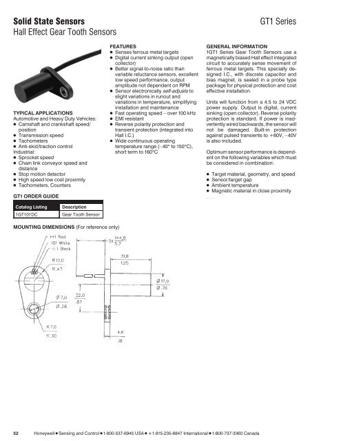
PDFINFO p a g e - 0 5 2<strong>Solid</strong> <strong>State</strong> <strong>Sensors</strong><strong>Hall</strong> <strong>Effect</strong> <strong>Gear</strong> <strong>Tooth</strong> <strong>Sensors</strong><strong>GT1</strong> <strong>Series</strong>TYPICAL APPLICATIONSAutomotive and Heavy Duty Vehicles: Camshaft and crankshaft speed/position Transmission speed Tachometers Anti-skid/traction controlIndustrial: Sprocket speed Chain link conveyor speed anddistance Stop motion detector High speed low cost proximity Tachometers, Counters<strong>GT1</strong> ORDER GUIDEFEATURES Senses ferrous metal targets Digital current sinking output (opencollector) Better signal-to-noise ratio thanvariable reluctance sensors, excellentlow speed performance, outputamplitude not dependent on RPM Sensor electronically self-adjusts toslight variations in runout andvariations in temperature, simplifyinginstallation and maintenance Fast operating speed – over 100 kHz EMI resistant Reverse polarity protection andtransient protection (integrated into<strong>Hall</strong> I.C.) Wide continuous operatingtemperature range (–40° to 150°C),short term to 160°CGENERAL INFORMATION1<strong>GT1</strong> <strong>Series</strong> <strong>Gear</strong> <strong>Tooth</strong> <strong>Sensors</strong> use amagnetically biased <strong>Hall</strong> effect integratedcircuit to accurately sense movement offerrous metal targets. This specially designedI.C., with discrete capacitor andbias magnet, is sealed in a probe typepackage for physical protection and costeffective installation.Units will function from a 4.5 to 24 VDCpower supply. Output is digital, currentsinking (open collector). Reverse polarityprotection is standard. If power is inadvertentlywired backwards, the sensor willnot be damaged. Built-in protectionagainst pulsed transients to +60V, –40Vis also included.Optimum sensor performance is dependenton the following variables which mustbe considered in combination: Target material, geometry, and speed Sensor/target gap Ambient temperature Magnetic material in close proximityCatalog Listing1<strong>GT1</strong>01DCDescription<strong>Gear</strong> <strong>Tooth</strong> SensorMOUNTING DIMENSIONS (For reference only)52 HoneywellSensingandControl1-800-537-6945USA1-815-235-6847International1-800-737-3360Canada
PDFINFO p a g e - 0 5 3<strong>Solid</strong> <strong>State</strong> <strong>Sensors</strong><strong>Hall</strong> <strong>Effect</strong> <strong>Gear</strong> <strong>Tooth</strong> <strong>Sensors</strong><strong>GT1</strong> <strong>Series</strong>SENSOR SPECIFICATIONSAll values were measured using 1 K pull-up resistor.ElectricalCharacteristicsAbsoluteMaximumRatings*SwitchingCharacteristics**Supply VoltageSupply CurrentOutput Voltage (output low)Output Current (output high)Switching TimeRise (10 to 90%)Fall (90 to 10%)Supply Voltage (Vs)Voltage Externally AppliedTo Output (output high)Output CurrentTemperature RangeStorageOperatingOperate PointRelease PointDifferential Travel4.5 to 24 VDC10 mA typ., 20 mA max.0.4 V max.10 µA max. leakage into sensor15 µsec. max.1.0 µsec. max.±30 VDC continuous–0.5 to +30 V40 mA sinking–40 to 150° (–40 to 302°F)–40 to 150° C(–40to302°F)3.7±1.25° (3,28±1,13 mm)4.7±2.50° (4,16±2,21 mm)8.4±3.70° (7,45±3,34 mm)* As with all solid state components, sensor performance can be expected to deteriorate asrating limits are approached; however, sensors will not be damaged unless the limits areexceeded.** See Reference Target table.TARGET GUIDELINESThe Target Guidelines table provides basicparameters when an application is notrestricted to a specific target.Any target wheel that exceeds the followingminimum specifications can besensed over the entire temperature rangeof –40° to 150°C with any sensing gap upto .080 in. (2,0 mm). This data is based ona 4 in. (102 mm) diameter wheel, rotating10 to 3600 RPM.REFERENCE TARGET/CONDITIONSCharacteristics will vary due to target size,geometry, location, and material. <strong>Sensors</strong>pecifications were derived using a coldrolledsteel reference target. See table,right, for reference target configurationand evaluation conditions.TargetDiameter:4 in. (101,6 mm)<strong>Tooth</strong> Width: .350 in. (8,89 mm)Thickness:.250 in. (6,35 mm)Test ConditionsAir Gap: .040 to .080 in. (1,02 to 2,03 mm)V Supply: 4.5 to 24 VRPM: 10 min., 3600 max.Integral MagnetReference Target Dimensions<strong>Tooth</strong> Height:<strong>Tooth</strong> Width:<strong>Tooth</strong> Spacing:Target Thickness:.200 in. (5,06 mm) min..100 in. (2,54 mm) min..400 in. (10,16 mm) min..250 in. (6,35 mm)Sensor Output (with pull-up resistor addedto output circuit)HoneywellSensingandControl1-800-537-6945USA1-815-235-6847International1-800-737-3360Canada 53