I2C Communication with Honeywell Digital Output Pressure Sensors
I2C Communication with Honeywell Digital Output Pressure Sensors
I2C Communication with Honeywell Digital Output Pressure Sensors
- No tags were found...

You also want an ePaper? Increase the reach of your titles
YUMPU automatically turns print PDFs into web optimized ePapers that Google loves.
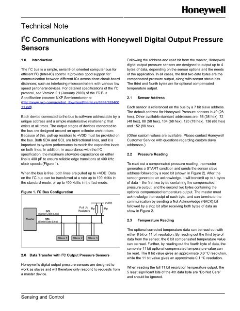
Technical NoteI 2 C <strong>Communication</strong>s <strong>with</strong> <strong>Honeywell</strong> <strong>Digital</strong> <strong>Output</strong> <strong>Pressure</strong><strong>Sensors</strong>1.0 IntroductionThe I 2 C bus is a simple, serial 8-bit oriented computer bus forefficient I 2 C (Inter-IC) control. It provides good support forcommunication between different ICs across short circuit-boarddistances, such as interfacing microcontrollers <strong>with</strong> various lowspeed peripheral devices. For detailed specifications of the I 2 Cprotocol, see Version 2.1 (January 2000) of the I 2 C BusSpecification (source: NXP Semiconductor at(http://www.nxp.com/acrobat_download/literature/9398/39340011.pdf).Each device connected to the bus is software addressable by aunique address and a simple master/slave relationship thatexists at all times. The output stages of devices connected tothe bus are designed around an open collector architecture.Because of this, pull-up resistors to +VDD must be provided onthe bus. Both SDA and SCL are bidirectional lines, and it isimportant to system performance to match the capacitive loadson both lines. In addition, in accordance <strong>with</strong> the I 2 Cspecification, the maximum allowable capacitance on eitherline is 400 pF to ensure reliable edge transitions at 400 kHzclock speeds (Figure 1).When the bus is free, both lines are pulled up to +VDD. Dataon the I 2 C-bus can be transferred at a rate up to 100 kbit/s inthe standard-mode, or up to 400 kbit/s in the fast-mode.Figure 1. I 2 C Bus ConfigurationMasterSCL(Serial Clock Line)SDL(Serial Data Line)Pull UpResistors RpSlave 1 Slave 2 Slave 3+VDD2.0 Data Transfer <strong>with</strong> I 2 C <strong>Output</strong> <strong>Pressure</strong> <strong>Sensors</strong><strong>Honeywell</strong>’s digital output pressure sensors are designed towork as slaves and will therefore only respond to requests froma master device.RpFollowing the address and read bit from the master, <strong>Honeywell</strong>digital output pressure sensors are designed to output up to 4bytes of data, depending on the sensor options and the needsof the application. In all cases, the first two data bytes are thecompensated pressure output, along <strong>with</strong> sensor status bits.The third and fourth bytes are for optional compensatedtemperature output.2.1 Sensor AddressEach sensor is referenced on the bus by a 7 bit slave address.The default address for <strong>Honeywell</strong> <strong>Pressure</strong> sensors is 40 (28hex). Other available standard addresses are: 56 (38 hex), 72(48 hex), 88 (58 hex), 104 (68 hex), 120 (78 hex), 136 (88 hex)and 152 (98 hex).(Other custom values are available. Please contact <strong>Honeywell</strong>Customer Service <strong>with</strong> questions regarding custom slaveaddresses.)2.2 <strong>Pressure</strong> ReadingTo read out a compensated pressure reading, the mastergenerates a START condition and sends the sensor slaveaddress followed by a read bit (shown in Figure 2). After thesensor generates an acknowledge, it will transmit up to 4 bytesof data – the first two bytes containing the compensatedpressure output, and the second two bytes containing theoptional compensated temperature output. The master mustacknowledge the receipt of each byte, and can terminate thecommunication by sending a Not Acknowledge (NACK) bitfollowed by a stop bit after receiving both bytes of data asshow in Figure 2.2.3 Temperature ReadingThe optional corrected temperature data can be read out <strong>with</strong>either 8 bit or 11 bit resolution. By reading out the third byte ofdata from the sensor, the 8 bit compensated temperature valuecan be read. Further, by reading out the fourth byte of data, thecomplete 11 bit optional compensated temperature value canbe read. The 8 bit value gives an approximate 0.8 C resolution,while the 11 bit value gives an approximate 0.1 C resolution.When reading the full 11 bit resolution temperature output, the5 least significant bits of the 4th data byte are “Do Not Care”and should be ignored.Sensing and Control
I 2 C <strong>Communication</strong> <strong>with</strong> <strong>Honeywell</strong> <strong>Digital</strong> <strong>Output</strong><strong>Pressure</strong> <strong>Sensors</strong>Figure 2. I 2 C <strong>Pressure</strong> and Temperature Measurement Packets ReadoutTwo Byte Data ReadoutData Byte 1 Data Byte 2StartA6 A5 A4 A3 A2 A1 A0 1ACKS1 S0 B13 B12 B11 B10 B9B8ACKB7 B6 B5 B4 B3 B2 B1 B0NACKSTOPSlave Address [6:0]ReadStatusBridge Data [13:8]Bridge Data [7:0]Three Byte Data ReadoutData Byte 1 Data Byte 2 Data Byte 3StartA6 A5 A4 A3 A2 A1 A0 1ACKS1 S0 B13 B12 B11 B10 B9B8ACKB7 B6 B4 B5 B3 B2 B1 B0ACKT10 T9 T8 T7 T6 T5 T4 T3NACKSTOPSlave Address [6:0]ReadStatusBridge Data [13:8]Bridge Data [7:0]Temperature Data [10:3]Four Byte Data ReadoutData Byte 1 Data Byte 2 Data Byte 3 Data Byte 4StartA6 A5 A4 A3 A2 A1 A0 1ACKS1 S0 B13 B12 B11 B10 B9B8ACKB7 B6 B5 B4 B3 B2 B1 B0ACKT10 T9 T8 T7 T6 T5 T4 T3ACKT2 T1 T0 X X X XXNACKSTOPSlave Address [6:0]ReadStatusBridge Data [13:8]Bridge Data [7:0]Temperature Data [10:3] Temperature Data [2:0]Bits generated by masterBits generated by slave (sensor)Note: For sensors that do not offer the optional compensated temperature output, the sensor will still output the third and fourthbytes of data, but the information contained in these bytes is non-corrected data, and should not be used.2.4 Status Bits<strong>Honeywell</strong> digital output pressure sensors offer both standardand optional diagnostics to ensure robust system operation incritical applications. The diagnostic states are indicated by thefirst two Most Significant Bits of Data Byte 1.Four diagnostic states are indicated by the 2 status bits (Table1 ).Table 1. Diagnostic Conditions indicated by Status BitsStatus BitsS1S0Definition0 0 normal operation, valid data0 1 device in command mode*1 0stale data: data that has already been fetchedsince the last measurement cycle, or datafetched before the first measurement hasbeen completed1 1 diagnostic conditionNote: *Command mode is used for programming the sensor.This mode should not be seen during normal operation.Optional diagnostics for <strong>Honeywell</strong> digital output pressuresensors consist of:Loss of sense element connectionShort circuit of sense elementWhen the two status bits are “11”, one of the above mentioneddiagnostic faults is indicated.When the status bits read “10”, “stale” data is indicated, thismeans that the data that already exists in the sensor’s outputbuffer has already been fetched by the master, and has not yetbeen updated <strong>with</strong> the next data from the current measurementcycle. This can happen when the master polls the data quickerthan the sensor can update the output buffer.(Please contact <strong>Honeywell</strong> Customer Service <strong>with</strong> questionsregarding the availability of optional <strong>Pressure</strong> Sensordiagnostics.)3. 0 Calculation of the <strong>Pressure</strong> from the <strong>Digital</strong> <strong>Output</strong>For <strong>Honeywell</strong> digital output pressure sensors, the output ofthe device can be expressed by the transfer function of thedevice as shown in Equation 1.Standard diagnostics for <strong>Honeywell</strong> digital output pressuresensors consist of an EEPROM (Electrically ErasableProgrammable Read-Only Memory) signature used to validatethe EEPROM contents during startup. In the event that anyEEPROM contents change after calibration, a diagnosticcondition will be flagged.Equation 1: <strong>Pressure</strong> Sensor Transfer Function<strong>Output</strong>max- <strong>Output</strong>min<strong>Output</strong>Pmax-Pmin(<strong>Pressure</strong>-P min)<strong>Output</strong>min2 <strong>Honeywell</strong> Sensing and Control
I 2 C <strong>Communication</strong> <strong>with</strong> <strong>Honeywell</strong> <strong>Digital</strong> <strong>Output</strong><strong>Pressure</strong> <strong>Sensors</strong>Rearranging this equation to solve for pressure, we getEquation 2:Equation 2: <strong>Pressure</strong> <strong>Output</strong> Function<strong>Pressure</strong>(<strong>Output</strong> - <strong>Output</strong> min)(<strong>Pressure</strong>(<strong>Output</strong> max - <strong>Output</strong>maxmin- <strong>Pressure</strong>)min)<strong>Pressure</strong>Where:<strong>Output</strong> max= output at max. pressure [counts]<strong>Output</strong> min= output at min. pressure [counts]<strong>Pressure</strong> max= max. value of pressure range [bar, psi, kPa, etc.]<strong>Pressure</strong> min= min. value of pressure range [bar, psi, kPa, etc.]<strong>Pressure</strong> = pressure reading [bar, psi, kPa, etc.]<strong>Output</strong> = digital pressure reading [counts]As an example, the pressure will be calculated for a -1 psi to1 psi differential sensor <strong>with</strong> a 10% to 90% calibration and apressure output of 1657 (decimal) counts:<strong>Output</strong> max= 14745 counts (90% of 2 14 counts or 0x3999)<strong>Output</strong> min= 1638 counts (10% of 2 14 counts or 0x0666)<strong>Pressure</strong> max= 1 psi<strong>Pressure</strong> min= -1 psi<strong>Pressure</strong> = pressure in psi<strong>Output</strong> = 1657 counts<strong>Pressure</strong><strong>Pressure</strong><strong>Pressure</strong><strong>Pressure</strong>(1657 1638) (1 ( 1))(14745 1638)(19) (2)131073813107(0.002899)<strong>Pressure</strong> 0.997 psi((1)(1)1)4.0 Calculation of Optional Temperature from the <strong>Digital</strong><strong>Output</strong>For <strong>Honeywell</strong> digital output pressure sensors <strong>with</strong> the optionalcompensated temperature output, the output can be convertedto C using Equation 3:Equation 3: Temperature Conversion FunctionTemperatur e (C)<strong>Output</strong> (dec)2047200If the 8 bit temperature output is used, the data must first beshifted left by 3 bits and have the 3 Least Significant Bits set to“0’s” for the equation to work.(1)50minAs an example, the optional compensated temperature outputwill be calculated for a sensor <strong>with</strong> an 8 bit temperature outputof 255:Step 1: Left shift the above 8-bit value by 3 places and appendthe 3 LSBs <strong>with</strong> 0s:<strong>Digital</strong> Temperature <strong>Output</strong> (8 – bit) = 255 = 11111111b11111111000b = 2040Step 2: Use the adjusted value and plug into Equation 3:Temperatur eTemperatur e20402047149.31200CAs a second example, the optional compensated temperatureoutput will be calculated for a sensor <strong>with</strong> an 11 bittemperature output of 1456:50Step 1: Plug the digital temperature output value into Equation3:1456Temperatur e 200 502047Temperatur e92.265.0 Timing and Level ParametersCTable 2. Parameters for I 2 C Bus <strong>Communication</strong> <strong>with</strong><strong>Honeywell</strong> <strong>Digital</strong> <strong>Output</strong> <strong>Pressure</strong> <strong>Sensors</strong>I 2 C Parameter Sym. Min. Typ. Max. UnitSCL clock frequency f SCL 100 - 400 kHzStart condition holdtime relative to SCL t HDSTA 0.1 - - μsedgeMinimum SCL clocklow width*t LOW 0.6 - - μsMinimum SCL clockhigh width*t HIGH 0.6 - - μsStart condition setuptime relative to t SUSTA 0.1 - - μsSCL edgeData hold time onSDA relative to SCL t HDDAT 0 - - μsedgeData set-up time onSDA relative to SCL t SUDAT 0.1 - - μsedgeStop condition setuptime on SCLt SUSTO 0.1 - - μsBus free timebetween stopcondition and startt BUS 2 - - μscondition<strong>Output</strong> level low Outlow - 0 0.2 VDD<strong>Output</strong> level high Outhigh 0.8 1 - VDDPull-up resistanceon SDA and SCLRp 1 - 50 kOhmNote: *Combined low and high widths must equal or exceedminimum SCL period.<strong>Honeywell</strong> Sensing and Control 3
I 2 C <strong>Communication</strong> <strong>with</strong> <strong>Honeywell</strong> <strong>Digital</strong> <strong>Output</strong><strong>Pressure</strong> <strong>Sensors</strong>Figure 3: I 2 C Bus Timing DiagramSDASCLt HDSTAt LOWt SUDATt HDSTAt BUSt HDDAT t HIGH t SUSTAt SUSTOWARNINGPERSONAL INJURYDO NOT USE these products as safety or emergency stopdevices or in any other application where failure of theproduct could result in personal injury.Failure to comply <strong>with</strong> these instructions could result indeath or serious injury.WARRANTY/REMEDY<strong>Honeywell</strong> warrants goods of its manufacture as being free ofdefective materials and faulty workmanship. <strong>Honeywell</strong>’sstandard product warranty applies unless agreed to otherwiseby <strong>Honeywell</strong> in writing; please refer to your orderacknowledgement or consult your local sales office for specificwarranty details. If warranted goods are returned to <strong>Honeywell</strong>during the period of coverage, <strong>Honeywell</strong> will repair or replace,at its option, <strong>with</strong>out charge those items it finds defective. Theforegoing is buyer’s sole remedy and is in lieu of all otherwarranties, expressed or implied, including those ofmerchantability and fitness for a particular purpose. In noevent shall <strong>Honeywell</strong> be liable for consequential, special,or indirect damages.While we provide application assistance personally, throughour literature and the <strong>Honeywell</strong> web site, it is up to thecustomer to determine the suitability of the product in theapplication.Specifications may change <strong>with</strong>out notice. The information wesupply is believed to be accurate and reliable as of this printing.However, we assume no responsibility for its use.WARNINGMISUSE OF DOCUMENTATIONThe information presented in this technical note is forreference only. DO NOT USE this document as a productinstallation guide.Complete installation, operation, and maintenanceinformation is provided in the instructions supplied <strong>with</strong>each product.Failure to comply <strong>with</strong> these instructions could result indeath or serious injury.SALES AND SERVICE<strong>Honeywell</strong> serves its customers through a worldwide networkof sales offices, representatives and distributors. Forapplication assistance, current specifications, pricing or nameof the nearest Authorized Distributor, contact your local salesoffice or:E-mail: info.sc@honeywell.comInternet: www.honeywell.com/sensingPhone and Fax:Asia Pacific +65 6355-2828+65 6445-3033 FaxEurope +44 (0) 1698 481481+44 (0) 1698 481676 FaxLatin America +1-305-805-8188+1-305-883-8257 FaxUSA/Canada +1-800-537-6945+1-815-235-6847+1-815-235-6545 FaxSensing and Control<strong>Honeywell</strong>1985 Douglas Drive NorthGolden Valley, MN 55422www.honeywell.com/sensing008201-1-EN IL50 GLO Printed in USAOctober 2010Copyright © 2010 <strong>Honeywell</strong> International Inc. All rights reserved.