- Page 2 and 3: Warning ● The contents in this do
- Page 5 and 6: IC 1 ○ ○ ○ ○ ○ ○ ○
- Page 7 and 8: 1-1 Regulator IC Switching Mode Reg
- Page 9 and 10: 1-1-1 Linear Regulator IC Applicati
- Page 11: SI-3000LUS Series ■External Dimen
- Page 15 and 16: SI-3000HM Series ■External Dimens
- Page 17 and 18: SI-3000LSA Series ■External Dimen
- Page 19 and 20: SI-3000KS Series ■External Dimens
- Page 21 and 22: SI-3000KMS Series ■External Dimen
- Page 23 and 24: SI-3000KM Series ■Electrical Char
- Page 25 and 26: IC 23
- Page 27 and 28: SI-3000KD Series ■Electrical Char
- Page 29 and 30: IC 27
- Page 31 and 32: SI-3000LLSL Series ■External Dime
- Page 33 and 34: SI-3000ZD Series ■External Dimens
- Page 35 and 36: SI-3000B Series ■External Dimensi
- Page 37 and 38: SI-3000N Series ■External Dimensi
- Page 39 and 40: SI-3003N Series ■External Dimensi
- Page 41 and 42: SI-3000F Series ■Electrical Chara
- Page 43 and 44: IC 41
- Page 45 and 46: SI-3000KF Series ■Electrical Char
- Page 47 and 48: IC 45
- Page 49 and 50: SI-3001N Series ■External Dimensi
- Page 51 and 52: SI-3000C Series ■Electrical Chara
- Page 53 and 54: SI-3000C Series ■Typical Connecti
- Page 55 and 56: SI-3000R Series ■Block Diagram
- Page 57 and 58: SI-3002N Series ■External Dimensi
- Page 59 and 60: SI-3000V Series ■External Dimensi
- Page 61 and 62: SI-3000J Series ■External Dimensi
- Page 63 and 64:
SI-3000ZF Series ■External Dimens
- Page 65 and 66:
1-1-2 Switching Mode Regulator IC A
- Page 67 and 68:
SAI Series ■External Dimensions (
- Page 69 and 70:
SI-8000W Series ■External Dimensi
- Page 71 and 72:
SI-8000JD Series ■External Dimens
- Page 73 and 74:
SI-8000SD Series ■External Dimens
- Page 75 and 76:
SPI-8000A Series ■External Dimens
- Page 77 and 78:
IC 75
- Page 79 and 80:
SI-8000RD Series ■External Dimens
- Page 81 and 82:
SI-8000E Series ■External Dimensi
- Page 83 and 84:
SI-8000JF Series ■External Dimens
- Page 85 and 86:
SI-8000GL Series ■External Dimens
- Page 87 and 88:
SI-8000S Series ■External Dimensi
- Page 89 and 90:
11° 11° COMP + - SI-8011NVS ■Ex
- Page 91 and 92:
11° 11° COMP + - SI-8511NVS ■Ex
- Page 93 and 94:
+ - STA810M Series ■External Dime
- Page 95 and 96:
+ - STA820M Series ■External Dime
- Page 97 and 98:
SI-8400L/8500L Series ■External D
- Page 99 and 100:
1-1-3 Multi-Output Type Regulator I
- Page 101 and 102:
STA801M/802M Series ■External Dim
- Page 103 and 104:
SDI02 ■External Dimensions 2.54
- Page 105 and 106:
IC 103
- Page 107 and 108:
SPI-8001TW/SPI-8002TW ■Electrical
- Page 109 and 110:
SPI-8001TW/SPI-8002TW ■Typical Co
- Page 111 and 112:
SI-3000KWF Series ■External Dimen
- Page 113 and 114:
SI-3000KWD Series ■External Dimen
- Page 115 and 116:
SI-3000KWM Series ■External Dimen
- Page 117 and 118:
SLA3002M/3004M ■External Dimensio
- Page 119 and 120:
+ - + - + - + - + - + - + - + - + -
- Page 121 and 122:
IC 119
- Page 123 and 124:
1-2 Motor Driver IC Application Not
- Page 125 and 126:
SLA7022MU/SLA7029M/SMA7022MU/SMA702
- Page 127 and 128:
SMA7036M ■Internal Block Diagram
- Page 129 and 130:
SLA7027MU/SLA7024M/SLA7026M ■Inte
- Page 131 and 132:
SLA7031M/SLA7032M/SLA7033M ■Inter
- Page 133 and 134:
SLA7050M/SLA7051M/SLA7052M ■Inter
- Page 135 and 136:
SDK03M ■Typical Connection Diagra
- Page 137 and 138:
SLA7042M/SLA7044M ■Internal Block
- Page 139 and 140:
SLA7065M/SLA7066M/SLA7067M ■Inter
- Page 141 and 142:
SLA7060M/SLA7061M/SLA7062M ■Inter
- Page 143 and 144:
PG001M ■Internal Block Diagram
- Page 145 and 146:
SLA7611M ■Internal Block Diagram
- Page 147:
1-3 ICs for Switching Mode Power Su
- Page 150 and 151:
2 Transistor Application Note Since
- Page 152 and 153:
2-1 Transistor Audio Transistor ■
- Page 154 and 155:
2-1 Transistor Specifications List
- Page 156 and 157:
2-1 Transistor Part Number Applicat
- Page 158 and 159:
2-1 Transistor Part Number Applicat
- Page 160 and 161:
2-1 Transistor Part Number Applicat
- Page 162 and 163:
2-2 MOS FET Selection Guide By VDSS
- Page 164 and 165:
2-2 MOS FET Specifications List by
- Page 166 and 167:
2-2 MOS FET Absolute Maximum Rating
- Page 168 and 169:
2-3 Transistor and MOS FET Array Sp
- Page 170 and 171:
2-3 Transistor and MOS FET Array Pa
- Page 172 and 173:
2-3 Transistor and MOS FET Array Sp
- Page 174 and 175:
2-3 Transistor and MOS FET Array
- Page 176 and 177:
2-3 Transistor and MOS FET Array Sp
- Page 178 and 179:
2-3 Transistor and MOS FET Array Sp
- Page 180 and 181:
2-3 Transistor and MOS FET Array
- Page 182 and 183:
2-3 Transistor and MOS FET Array
- Page 184 and 185:
2-3 Transistor and MOS FET Array Sp
- Page 186 and 187:
2-3 Transistor and MOS FET Array Sp
- Page 188 and 189:
2-3 Transistor and MOS FET Array Pa
- Page 190 and 191:
Package Type (Dimensions) • STA 8
- Page 193 and 194:
3-1 Thyristor Application Note Sinc
- Page 195 and 196:
3-1 Thyristor Electrical Characteri
- Page 197 and 198:
3-2 Triac Electrical Characteristic
- Page 199 and 200:
3-3 PNPN Switch Element VBO (V) min
- Page 201:
Package Type (Dimensions) • STA 1
- Page 204 and 205:
4 Diode Taping Specifications Tapin
- Page 206 and 207:
4 Diode Surface-Mount Taping Specif
- Page 208 and 209:
4 Diode Marking Guide ■ 1 Axial (
- Page 210 and 211:
4-1 Rectifier Diode VRM (V) IF (AV)
- Page 212 and 213:
4-2 Fast Recovery Diode VRM (V) IF
- Page 214 and 215:
4-3 Ultrafast Recovery Diode VRM (V
- Page 216 and 217:
4-4 Schottky Barrier Diode Standard
- Page 218 and 219:
4-4 Schottky Barrier Diode Low IR
- Page 220 and 221:
4-6 Damper Diode Damper Diode ●Fo
- Page 222 and 223:
4-7 Avalanche Diode with Built-in T
- Page 224 and 225:
4-9 Silicon Varistor ●Symmetrical
- Page 226 and 227:
Package Type (Dimensions) • No. 1
- Page 229 and 230:
LED 5 ○ ○ ○ ○ ○ ○ ○
- Page 231 and 232:
5 LED ■ Soldering conditions ●T
- Page 233 and 234:
5 LED Infrared LED (1) Ex: SID 1 0
- Page 235 and 236:
5 LED Taping Specifications Lamp Ty
- Page 237 and 238:
5 LED Surface Mount Types Unicolor
- Page 239 and 240:
5-1-1 Unicolor lamps ■5φ Round S
- Page 241 and 242:
5-1-1 Unicolor lamps ■4φ Round W
- Page 243 and 244:
5-1-1 Unicolor lamps ■3φ Cylinde
- Page 245 and 246:
5-1-1 Unicolor lamps ■2 × 4 Rect
- Page 247 and 248:
5-1-2 Bicolor lamps ■5φ Round St
- Page 249 and 250:
5-1-3 Unicolor surface mount ■1.6
- Page 251 and 252:
5-1-4 Bicolor surface mount ■1.6
- Page 253 and 254:
5-2 Infrared LED Absolute Maximum R
- Page 255 and 256:
External Dimensions List ■Externa
- Page 257 and 258:
External Dimensions List ■Externa
- Page 259 and 260:
External Dimensions List ■Externa
- Page 261:
Ordering Information Please place o
- Page 264 and 265:
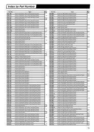
Part Number Index in Alphanumeric O
- Page 266 and 267:
Part Number Index in Alphanumeric O
- Page 268 and 269:
Part Number Index in Alphanumeric O
- Page 270 and 271:
Part Number Index in Alphanumeric O
- Page 272 and 273:
Part Number Index in Alphanumeric O
- Page 274 and 275:
Part Number Index in Alphanumeric O
- Page 276 and 277:
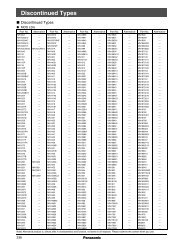
Discontinued Products and Service P
- Page 278 and 279:
Discontinued Products and Service P
- Page 280 and 281:
MEMO 278