Series 1 2030, 2060x and 4060x Amplifier Manual
Series 1 2030, 2060x and 4060x Amplifier Manual
Series 1 2030, 2060x and 4060x Amplifier Manual

You also want an ePaper? Increase the reach of your titles
YUMPU automatically turns print PDFs into web optimized ePapers that Google loves.
, <strong>2060x</strong> <strong>and</strong> <strong>4060x</strong><br />
AMPLIFIERS OWNER MANUAL
Dear Customer,<br />
Congratulations on your purchase of America’s finest br<strong>and</strong> of car audio<br />
amplifiers. At Rockford Fosgate we are committed to musical reproduction<br />
at its best, <strong>and</strong> we are pleased you chose our product. Through years of<br />
engineering expertise, h<strong>and</strong> craftsmanship <strong>and</strong> critical testing procedures<br />
we have created a wide range of products that reproduce music with all the<br />
clarity <strong>and</strong> richness you deserve.<br />
For maximum performance we recommend you have your new Rockford<br />
Fosgate product installed by an Authorized Rockford Fosgate Dealer, as we<br />
provide specialized training through Rockford Technical Training Institute<br />
(RTTI). Please read your warranty <strong>and</strong> retain your receipt <strong>and</strong> original<br />
carton for possible future use.<br />
To add the finishing touch to your new Rockford Fosgate image order your<br />
Rockford accessories, which include everything from T-shirts <strong>and</strong> jackets to<br />
hats <strong>and</strong> sunglasses.<br />
To get a free brochure on Rockford Fosgate products <strong>and</strong> Rockford accessories,<br />
please call l-800-366-2349 or FAX l-602-894-1528 in the U.S. For<br />
Canada, call Korbon Trading at 416-567-1920. For International orders FAX<br />
+001-l-602-967-8132 or call +001-l-602-967-3565.<br />
PRACTICE SAFE SOUND<br />
CONTINUOUS EXPOSURE TO SOUND PRESSURE LEVELS OVER<br />
1OOdB MAY CAUSE PERMANENT HEARING LOSS. HIGH POWERED<br />
AUTOSOUND SYSTEMS MAY PRODUCE SOUND PRESSURE LEVELS<br />
WELL OVER 130dB. USE COMMON SENSE AND PRACTICE SAFE<br />
SOUND.<br />
The serial number can be found on the outside of the box. Please record it in<br />
the space provided below as your permanent record. This will become useful<br />
in recovering your amplifier if it is ever stolen <strong>and</strong> serve as verification of your<br />
factory warranty.<br />
Serial Number:<br />
Model Number:
TABLE OF CONTENTS<br />
SPECIFICATIONS ........................................................................... 1<br />
Introduction ....................................................................................... 3<br />
Features <strong>and</strong> Benefits ............................................................... 3<br />
Controls <strong>and</strong> Features ....................................................................... 4<br />
Top View of <strong>Amplifier</strong> <strong>and</strong> End Caps ......................................... 4<br />
Input/LED Side.. .......................................................................... 5<br />
Power/Speaker Side ................................................................... 6<br />
Installation Considerations ............................................................... 7<br />
Tools Needed ............................................................................. 8<br />
Battery & Charging ............................................................................ 8<br />
Mounting <strong>and</strong> Location ..................................................................... 9<br />
Trunk Mounting ........................................................................... 9<br />
Passenger Mounting .................................................................. 9<br />
Wiring the <strong>Series</strong> 1.......................................................................... 10<br />
Power ...................................................................................... 10<br />
Ground.. .................................................................................... 11<br />
Remote Turn-on ....................................................................... 11<br />
Input.. ........................................................................................ 11<br />
Speakers ..................................................................................<br />
Bridged/Mono Configuration .................................................... 12<br />
Passive Crossover Impedance ................................................ 12<br />
Table of Crossover Component Values ......................................... 14<br />
Active Crossover Mode Selections for the <strong>2060x</strong> <strong>and</strong> <strong>4060x</strong> .......... 15<br />
Crossover Frequency Settings ................................................ 15<br />
Wiring Diagrams.. ........................................................................... 16<br />
Troubleshooting ............................................................................. 22<br />
Dynamic Power Measurements ..................................................... 25<br />
Warranty Information.. .................................................................... 28<br />
11
INTRODUCTION<br />
Features<br />
<strong>and</strong><br />
Benefits<br />
This manual provides information on the features, installation<br />
<strong>and</strong> operation of the <strong>Series</strong> 1 <strong>2030</strong>,<strong>2060x</strong> <strong>and</strong> <strong>4060x</strong><br />
<strong>Amplifier</strong>s. We suggest you save this manual for future<br />
reference.<br />
We strongly recommend you have your Authorized Rockford<br />
Fosgate Dealer <strong>and</strong> Service Center install your new<br />
<strong>Series</strong> 1 amplifier. If you do choose to install your <strong>Series</strong><br />
1 amplifier yourself, please be sure to read the entire<br />
manual before beginning.<br />
The Rockford <strong>Series</strong> 1 automotive stereo power amplifiers<br />
provide state-of-art sound in cars, vans, boats, or wherever<br />
a high current 12 volt power source is available. Some of<br />
the features found in the <strong>Series</strong> 1 amplifiers are listed<br />
below.<br />
Pulse Width Modulated (PWM) DC/DC Non-Regulated<br />
Power Supply assures wider dynamic headroom than the<br />
more common regulated power supplies.<br />
High Current/High Voltage Output delivers the power<br />
needed for all listening levels <strong>and</strong> music frequencies so<br />
you can hear every single note.<br />
N-Type V-FET Output Drive Circuitry delivers music with<br />
lower noise <strong>and</strong> distortion while maintaining a higher slew<br />
rate, increased efficiency <strong>and</strong> higher power output capability<br />
than most amplifiers of this class.<br />
High or Low Level Adjustable Input Sensitivity permits<br />
maximum compatibility with your source units. This allows<br />
you to adjust the input sensitivity level of the power amplifier<br />
for RCA (preamp level) or speaker (high level) inputs.<br />
Active Electronic Crossover Module built-into the <strong>2060x</strong><br />
<strong>and</strong> <strong>4060x</strong> features 12 dB/octave Butterworth filters. The<br />
independent crossover modes in these plug-in modules<br />
allow for various configuration possibilities.<br />
Real Time Power Protection (R.T.P.P.) allows for the<br />
greatest power output under all load conditions. When<br />
output reaches an unsafe level it will be reduced, unlike<br />
current limiting which often causes premature protection or<br />
failure to protect at all.<br />
3
Discrete Surface Mount Technology is a manufacturing<br />
method that allows the packaging of complex circuitry<br />
in small areas, reducing noise <strong>and</strong> crosstalk for lower<br />
distortion.<br />
Gold-Plated Connectors of high quality provide lower<br />
resistance <strong>and</strong> better reliability.<br />
To get a better underst<strong>and</strong>ing of the <strong>Series</strong> 1, let’s take a<br />
closer look.<br />
CONTROLS AND FEATURES<br />
<strong>Series</strong> 1<br />
Housing<br />
End Caps<br />
This section describes the various controls <strong>and</strong> features<br />
of the <strong>Series</strong> 1 <strong>2030</strong>, <strong>2060x</strong> <strong>and</strong> <strong>4060x</strong> amplifiers.<br />
Top View of <strong>Amplifier</strong> <strong>and</strong> End Caps<br />
The extruded aluminum heatsink design of the <strong>Series</strong> 1<br />
was designed for high performance cooling. The raised<br />
design of the housing allows cables <strong>and</strong> wires to run<br />
underneath the unit. This provides for greater wiring<br />
flexibility <strong>and</strong> protects the cables from damage caused by<br />
excessive heat <strong>and</strong> bending.<br />
The removable end caps, which slide <strong>and</strong> snap into the<br />
housing, conceal the wiring <strong>and</strong> input cables <strong>and</strong> give the<br />
amplifier a clean, “stealth” look.
Low Level<br />
RCA Input<br />
Connectors<br />
High Level<br />
Speaker input<br />
Connector<br />
LED Power<br />
Indicator<br />
Input Gain<br />
Control<br />
Low Level Input Gain<br />
RCA input Control<br />
Connectors<br />
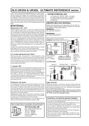
Input/LED Side<br />
I<br />
High Level<br />
Speaker Input<br />
Connector<br />
LED Power<br />
Indicator<br />
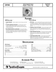
The amplifier’s signal input female RCA pin jacks should<br />
be connected to the source unit’s signal outputs with<br />
high-quality RCA cables. The connectors have been<br />
plated in gold to eliminate the possibility of corrosion that<br />
can cause signal deterioration.<br />
These connectors are used to connect to a source unit<br />
that does not provide low level RCA outputs. This connector<br />
accepts 1/8” spade lugs. Do not attempt to solder<br />
wires directly to this connector.<br />
The LED illuminates when the unit is in operation.<br />
This control is factory preset to 500 millivolts to match<br />
most radios <strong>and</strong> is variable from 250 millivolts to one volt.<br />
(More than likely it will not need adjusting.)<br />
If just a little movement of the volume control from the<br />
source unit drives the amplifier into distortion, reduce the<br />
input gain control so that the distortion doesn’t start until<br />
the source unit volume control is at about 3/4 of its<br />
rotation.
Power/<br />
Speaker<br />
Connectors<br />
;31lu<br />
----<br />
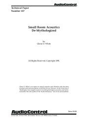
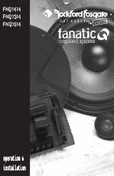
Power/Speaker Side<br />
.\ I<br />
Power / Speaker<br />
Connectors<br />
The gold-plated terminal block connectors are:<br />
B+<br />
GND<br />
AP<br />
+L-<br />
+R-<br />
Supplies power to the amplifier.<br />
Supplies ground to the amplifier.<br />
The amplifier is turned on by connecting the<br />
remote turn-on wire to the source unit’s “Auto<br />
Antenna” or remote turn-on lead, either of which<br />
should go to +12 volts when the source unit is<br />
activated.<br />
Connect the Right <strong>and</strong> Left channel outputs to the<br />
speakers.<br />
The terminal block connector accepts wire sizes from 10<br />
gauge to 20 gauge. *<br />
Spade connectors are not needed because of the design<br />
of the connector. The installer should be careful not to<br />
allow wires to fray or touch. The recommended strip<br />
length is 1/4” (.635cm).<br />
*Rockford Fosgate’s Perfect Interface line of accessories includes<br />
high quality power <strong>and</strong> speaker wire, gold-plated RCA<br />
interconnecting cables <strong>and</strong> other products to complete your<br />
installation. Ask your Authorized Rockford Fosgate Dealer<br />
about Perfect Interface.<br />
6
INSTALLATION CONSIDERATIONS<br />
This section focuses on some of the vehicle considerations<br />
for installing your new <strong>Series</strong> 1 amplifier. Checking<br />
your battery <strong>and</strong> current sound system, as well as preplanning<br />
your system layout <strong>and</strong> best wiring routes will<br />
save installation time. When deciding how to lay out your<br />
new system, be sure that each component will be easily<br />
accessible for making adjustments.<br />
Before beginning any installation, be sure to follow these<br />
simple rules:<br />
1.<br />
2.<br />
3.<br />
4.<br />
5.<br />
6.<br />
7.<br />
Be sure to carefully read <strong>and</strong> underst<strong>and</strong> the instructions<br />
before attempting to install the amplifier.<br />
For easier assembly, we suggest you run all wires<br />
prior to mounting your amplifier in place.<br />
Use only quality connectors for making connections.<br />
See your Authorized Rockford Fosgate Dealer for<br />
Perfect Interface wire enhancements.<br />
Think before you drill! Be careful not to cut or drill<br />
into gas tanks, fuel lines, brake or hydraulic lines,<br />
vacuum lines or electrical wiring when working on any<br />
vehicle.<br />
For safety, disconnect the battery ground cable prior<br />
to beginning the installation process.<br />
Never run wires underneath thevehicle. The cleanest,<br />
safest wiring connections are made by running the<br />
wire under the carpet or behind the side panels.<br />
Never leave wires exposed.<br />
Avoid running wires over or through sharp edges.<br />
Use grommets to protect wires routed through holes<br />
in metal.<br />
7
Tools<br />
Needed<br />
Supplies<br />
Needed<br />
ALWAYS protect the battery <strong>and</strong> electrical system<br />
from shorts with proper fusing. A fuse holder <strong>and</strong> fuse<br />
must be installed within 18” (45.72 cm) of the battery<br />
terminal to safeguard from possible damage or injury.<br />
This fuse <strong>and</strong> fuse holder is included with the <strong>Series</strong><br />
1 amplifier. (See installation instructions on page 10.)<br />
9. Grounding connections should be as short as possible<br />
<strong>and</strong> always connected to metal that is welded to<br />
the main body, or chassis, of the vehicle.<br />
Wire Cutters<br />
Wire Strippers<br />
Wire Crimpers<br />
Voltmeter<br />
Electric H<strong>and</strong> Drill with assorted bits<br />
Phillips Screwdriver<br />
Flat Blade Screwdriver<br />
Battery Post Wrench<br />
Power Wire<br />
10-12 AWG; approx. 17’ [518.72 cm])<br />
Grounding Wire<br />
(10-12 AWG.; max. length 1.5’ [45.72 cm])<br />
Remote (AP) Turn-On Wire<br />
(18 AWG; approx. 12’ [365.76 cm])<br />
Assorted wire connectors<br />
In-line butt connectors that match power <strong>and</strong><br />
ground wire AWG<br />
3/8” [.953cm] Battery Ring Terminal<br />
1/4” [.635cm] Ground Terminal<br />
1-1/2” [3.81 cm] #8 Pan Head Mounting Screws (4)<br />
BATTERY AND CHARGING<br />
<strong>Series</strong> 1 amplifiers will naturally put an extra load on your<br />
battery <strong>and</strong> charging system. We recommend you check<br />
your alternator capacity to ensure ample charging capability<br />
to h<strong>and</strong>le the additional load of your new <strong>Series</strong> 1<br />
equipment. Stock electrical systems in good condition will<br />
typically h<strong>and</strong>le the extra load of any individual <strong>Series</strong> 1<br />
unit without problems. If problems arise, we suggest you<br />
first check the charging system, then use a heavy duty<br />
battery <strong>and</strong>/or a high output alternator as needed.<br />
8
MOUNTING AND LOCATIONS<br />
Trunk<br />
Mounting<br />
Passenger<br />
Compartment<br />
Mounting<br />
The mounting location <strong>and</strong> position of the <strong>Series</strong> 1 will<br />
have a great effect on its ability to dissipate the heat<br />
generated in normal operation. The <strong>Series</strong> 1 has a<br />
heatsink designed for heat dissipation <strong>and</strong> internal overheating<br />
shutoff circuitry to avoid overheating. The amp is<br />
reasonably tolerant of mounting variations. However,<br />
care should be taken to ensure adequate ventilation.<br />
The temperature inside a trunk can reach as high as 175°<br />
F (80” C) during the summer months. Since the thermal<br />
shutoff point for the <strong>Series</strong> 1 is 195° F (90° C), it is easy<br />
to see that the amp must be mounted for maximum<br />
cooling capability. Mounting the amplifier on the floor or<br />
under the rear parcel tray prevents sufficient convectional<br />
air flow cooling. Mounting the unit vertically on a surface<br />
with the fin grooves running up <strong>and</strong> down usually results<br />
in the best cooling.<br />
Under the seat or floor mounting will work as long as there<br />
is a minimum of 1” (2.5 cm) of air gap above the amplifier<br />
heatsink.<br />
Vertical mounting of the amplifier is still the best.<br />
9
WIRING THE SERIES 1<br />
Power<br />
Caution! Be sure to avoid running the power wires<br />
near the low level input cables, antenna, sensitive<br />
equipment or harnesses. The power wires carry<br />
substantial currents <strong>and</strong> could induce noise.<br />
The gold B+ terminal must be connected direct/ly to the<br />
positive (+) terminal of the battery with an appropriate size<br />
vire. (See the Specifications Table for more information.)<br />
This provides a power source with a low voltage drop <strong>and</strong><br />
low noise.<br />
Be sure to use the supplied fuse <strong>and</strong> fuse holder<br />
within 18” (45.72 cm) of the battery’s positive terminal.<br />
Failure to do so may cause damage to the vehicle<br />
<strong>and</strong> the amplifier.<br />
Note: You will need to cut the wire loop that is attached<br />
to the fuse holder in half <strong>and</strong> splice the<br />
fuse into the power line using appropriate inline<br />
butt connectors.<br />
Power Fuse Wire Loop with Fuse<br />
-Cut here<br />
If the power wire must be extended beyond 17’ (518.16<br />
cm), we recommend the use of 10 gauge str<strong>and</strong>ed wire.<br />
10
Ground<br />
Remote<br />
Turn-on<br />
Input<br />
Speakers<br />
The GND terminal grounds the amplifier <strong>and</strong> is connected<br />
to the chassis of the vehicle. When grounding, scrape<br />
paint off metal to ensure a good, clean ground connection.<br />
To prevent ground loops, we recommend you refrain from<br />
extending the ground wire beyond 18” (45.72 cm) in any<br />
installation.<br />
The <strong>Series</strong> 1 amplifiers are turned on by supplying positive<br />
(+) 12 volts to the AP terminal. Usually the terminal<br />
is connected to the source unit’s “Accessory” or “Auto<br />
Antenna” lead, either of which will go to +12 volts when the<br />
source unit is activated.<br />
Although the majority of high-quality automotive source<br />
units have an Accessory or Antenna output, there may be<br />
exceptions. If the source unit has no Auto Antenna lead<br />
(or if the Auto Antenna goes down during tape operation),<br />
we recommend a switch in the car with one terminal<br />
connected to +12 volts <strong>and</strong> the other to the <strong>Series</strong> 1 AP<br />
lead. This will allow you to engage the amplifier manually.<br />
The amplifier’s signal input RCA jacks should be connected<br />
to the source unit’s signal outputs with high-quality<br />
braided or double-shielded interconnecting RCA cables.<br />
Note: Be sure to route the <strong>Series</strong> 1 signal input cable<br />
away from the main power wire <strong>and</strong> the car’s<br />
wiring harnesses to avoid noise coupling.<br />
If the source unit does not utilize RCA cables, connect the<br />
left <strong>and</strong> right positive speaker output wires from the<br />
source unit to the amplifier’s High Level Speaker Input<br />
Connector. The center pin is then connected to the<br />
chassis of the source unit.<br />
<strong>Series</strong> 1 amplifiers are rated for safe operation into loads<br />
of 2Q or greater in stereo mode, or 4Q in bridged/mono<br />
configurations. The primary loads on any amplifier come<br />
from directly connected speakers without using capacitors.<br />
The measured resistance for each side should not<br />
be less than 2R stereo or 4Q bridged/mono.<br />
11
Bridged/Mono<br />
Configuration<br />
Passive<br />
Crossover<br />
Impedance<br />
The <strong>Series</strong> 1 amplifiers are capable of bridged/mono<br />
configurations.<br />
This configuration enables you to:<br />
• Run a single woofer with stereo satellites<br />
• Run two bridged amplifiers as a high power stereo<br />
system<br />
• Run one amplifier with a bridged/mono woofer<br />
<strong>and</strong> another as a high-frequency stereo amp, etc.<br />
Note: The <strong>4060x</strong> allows the above 3 configurations<br />
all in one.<br />
For more information refer to the wiring diagrams beginning<br />
on page 16.<br />
Note: To bridge the amplifier, use the L+ <strong>and</strong> Rspeaker<br />
connectors.<br />
CAUTION! <strong>Series</strong> 1 amplifiers are not recommended<br />
for impedance loads below 2Q stereo or 452 bridged/<br />
mono.<br />
Be sure to observe proper speaker terminal polarity<br />
throughout the system. It is critical for the <strong>Series</strong> 1 to<br />
use the correct negative terminal for right <strong>and</strong> left<br />
channels, since the RIGHT NEGATIVE (-) TERMINAL<br />
is the “hot” terminal for the right speaker. DO NOT<br />
chassis ground any of the speaker leads as unstable<br />
operation may result.<br />
A passive crossover is a circuit that employs capacitors<br />
<strong>and</strong>/or coils <strong>and</strong> is placed on speaker leads between the<br />
amplifier <strong>and</strong> speaker’s circuit to delegate frequencies in<br />
the speaker’s optimum performance range.<br />
The most commonly used filter networks are 6 dB per<br />
octave systems. These are easy to construct <strong>and</strong> require<br />
a minimum number of parts. A filter network can perform<br />
one of three functions. These are High Pass, (capacitors),<br />
Low Pass (inductors, chokes or coils) <strong>and</strong> B<strong>and</strong>pass<br />
(combination of a capacitor <strong>and</strong> a coil).<br />
This result, limiting the types of frequency to the speaker,<br />
is directly dependent upon the speaker’s impedance <strong>and</strong><br />
component values.<br />
12
The most common filters used in speaker crossovers, as<br />
stated above, are 6 dB per octave which use one component<br />
per filter. Placing this filter in series with the circuit will<br />
reduce power to the speaker by 6 dB per octave above or<br />
below the crossover point depending on whether it is a<br />
High Pass or Low Pass filter. When passive crossover<br />
components are used in multiple speaker systems, the<br />
crossover system’s effect on the overall impedance should<br />
be taken into consideration along with the speaker’s<br />
impedance when determining amplifier loads.<br />
More complex systems such as 12 dB or 18 dB per octave<br />
can cause impedance problems if not professionally<br />
designed. If such a system is required, we recommend<br />
consulting an Authorized Rockford Fosgate Dealer.<br />
13
ACTIVE CROSSOVER MODE SELECTIONS<br />
FOR THE <strong>2060x</strong> AND <strong>4060x</strong><br />
Crossover<br />
Frequency<br />
Settings<br />
The <strong>Series</strong> 1 <strong>2060x</strong> <strong>and</strong> the <strong>4060x</strong> amplifiers feature a<br />
selectable electronic crossover. One module controls<br />
two output channels that can be configured in a High<br />
Pass, Low Pass, or Full Range (factory default) position.<br />
(Note: The <strong>4060x</strong> has 2 modules as it is a 4-channel<br />
amplifier). Selection is made by positioning a removable<br />
module card. Both the <strong>2060x</strong> <strong>and</strong> <strong>4060x</strong> are shipped with<br />
100 Hz 12 dB per octave Butterworth aligned crossover<br />
modules. Additional crossover frequency modules are<br />
availablefrom your Authorized Rockford Fosgate Dealer.<br />
Note: The factory default setting is Full Range.<br />
To change the crossover mode, remove the crossover<br />
module from the housing. Rotate the module to the<br />
desired setting <strong>and</strong> gently push the module back into the<br />
amplifier housing as shown on the diagram on the back<br />
of the amplifier.<br />
Example: The <strong>2060x</strong> is shipped with a 100 Hz module.<br />
With the module in the Full Range setting, the amplifier<br />
will pass through all 20 Hz - 20kHz frequencies.<br />
In the Low Pass setting, only those frequencies below<br />
100 Hz will pass through the amplifier.<br />
In the High Pass setting, only those above 100 Hz will<br />
pass through the amplifier.<br />
1.5
TROUBLESHOOTING<br />
This troubleshooting guide is intended to assist you with certain problems<br />
which may occur. If you still encounter problems, see your<br />
Authorized Rockford Dealer for assistance.<br />
Problem<br />
<strong>Amplifier</strong> will not play - Remote Turn-on light is off.<br />
Solution<br />
1. Check the DC voltage at the amplifier’s B+ terminal<br />
with a voltmeter. The voltage should measure between<br />
11.5V - 15.5V.<br />
2.<br />
If voltage is not found, check the battery, fuse, fuse<br />
housing <strong>and</strong> wire connections. Fix, repair, or replace<br />
accordingly.<br />
If the amplifier still does not play, check the voltage at<br />
the amplifier’s remote turn-on lead. The voltage<br />
should measure between 11V - 15V.<br />
a. If voltage is above or below the prescribed measurements,<br />
check for proper connections <strong>and</strong><br />
have the head unit checked by an Authorized<br />
Dealer or Service Center.<br />
b. If the remote turn-on current draw from the head<br />
unit is connected to multiple amps <strong>and</strong>/or electronics,<br />
the current draw may be too great. Check<br />
for proper connections. (Use a relay to suppress<br />
the excessive current draw.)<br />
Problem<br />
<strong>Amplifier</strong> will not play - Remote Turn-on light is on:<br />
Solution<br />
Unplug the head unit <strong>and</strong> test the amplifier with<br />
another working source unit (i.e., bench-test radio,<br />
walkman, etc.). If the amplifier plays, check the indash<br />
leads for cuts, breaks <strong>and</strong>/or shorts.<br />
If the amplifier still does not play, disconnect the<br />
existing speakers <strong>and</strong> connect a set of test speakers<br />
to the output of the amplifier (any type of speaker will<br />
do- i.e., simple home box type, bookshelf, raw speaker,<br />
etc.). If the amp plays, check for shorts or blown voice<br />
coils in the vehicle’s speaker system.<br />
22
<strong>Amplifier</strong> gets too hot.<br />
Solution<br />
Be sure the amplifier is properly mounted. You should<br />
be able to place your h<strong>and</strong> a few inches above the<br />
amplifier housing <strong>and</strong> feel the heat rising when the unit<br />
is on.<br />
Hot air rises. Consequently mount the amplifier with<br />
the heatsink fins aligned vertically. This allows the air<br />
to flow freely, carrying away the heat. Check to see<br />
that the heatsink fins are free of any obstruction (i.e.,<br />
carpet, seats, etc.).<br />
If #1 does not solve the problem, check to see that the<br />
impedance of the overall system is not less than 2Q<br />
stereo or 4Q bridged/mono. Using an AC impedance<br />
meter (such as the Perfect Interface IM-1), sweep<br />
from 20 Hz-20 kHz, <strong>and</strong> look for dips below 2Q.<br />
Be sure to test the bass region (20 Hz - 150 Hz) of your<br />
system. If the amplifier is bridged to those speakers,<br />
the load the amp sees is one-half (1/2) of the reading<br />
on the AC impedance meter.<br />
If the impedance level is below 2R, check for a bad<br />
speaker <strong>and</strong>/or crossover, proper usage of passive<br />
crossovers or shorted wires, or try rewiring the entire<br />
system.<br />
Problem<br />
<strong>Amplifier</strong> noise (Turn-On Pop)<br />
Solution<br />
Disconnect the RCA plugs from the amplifier <strong>and</strong><br />
recheck the amp by turning it on <strong>and</strong> off with the source<br />
unit. If turn-on pop goes away, connect a delay turnon<br />
module (Perfect Interface DT-1) to the amplifier.<br />
See your Authorized Rockford Fosgate Dealer for<br />
more information.<br />
If the noise persists, disconnect the turn-on wire from<br />
the head unit <strong>and</strong> use adifferent +12 volt power source<br />
to turn on the amplifier (i.e., battery direct). If the noise<br />
is gone, use a relay to switch +12 volts auto power<br />
from the clean power source.<br />
23
Problem<br />
Engine Noise (Whine)<br />
Solution<br />
1. Disconnect the speakers from the amplifier. Connect<br />
a test speaker to the amplifier output terminals. If the<br />
noise goes away, check your speaker leads, speakers<br />
<strong>and</strong> crossovers.<br />
2.<br />
If the noise persists, use a “shorting plug” to mute the<br />
input signal at the amplifier. If the noise goes away:<br />
a. Bypass all of the other equipment (i.e., crossovers<br />
<strong>and</strong> equalizers) <strong>and</strong> connect the head unit<br />
directly to the amp. If the noise disappears,<br />
reconnect the equipment one piece at a time,<br />
being sure to test for noise after each piece is<br />
installed. Logic indicates that the last unit installed<br />
when the noise returns is the culprit.<br />
Refer to the unit’s owner’s manual for more<br />
information.<br />
b. If the noise persists, run a new RCA line from<br />
your head unit to the amplifier. If there is no<br />
noise, replace the RCA cable.<br />
c. If the noise is still present after replacing the RCA<br />
cable, run the RCA cable on a different route.<br />
d. Isolate the grounds on the head unit so that there<br />
is only one grounding point. If the noise disappears,<br />
install the radio, using only one (1) grounding<br />
point. Isolate the radio chassis from the<br />
grounding on the dash, <strong>and</strong> use an antenna<br />
grounding loop isolator on the antenna.<br />
If noise persists, see your Authorized Rockford Fosgate<br />
Dealer.<br />
24
DYNAMIC POWER MEASUREMENTS<br />
About the Dynamic Power Rating Measurements<br />
The Audio Graph PowerCube is a test instrument used to<br />
measure the output of an amplifier. It makes measurements<br />
in accordance with IHF-202 st<strong>and</strong>ards. The IHF-<br />
202 st<strong>and</strong>ard is a Dynamic power measurement. It was<br />
developed as a means of measuring power in a manner<br />
that best represents the Real World operation of an<br />
amplifier. Many manufacturers, including Rockford Fosgate,<br />
at times will measure amplifier power into a fixed<br />
resistor (4 ohm, 2 ohm). While this method is useful in<br />
some types of evaluation <strong>and</strong> testing, it is not representative<br />
of an amplifier that is hooked up to a speaker <strong>and</strong><br />
playing music.<br />
Music<br />
Music is dynamic; sound waves are complex <strong>and</strong> constantly<br />
changing. In order to simulate this, the IHF-202<br />
st<strong>and</strong>ard calls for the input signal to the amplifier to be a<br />
1 kHz bursted tone. This signal is input (on) for a short<br />
period of time <strong>and</strong> then off for a “rested” period. The signal<br />
is gradually increased in level until the amplifier’s output<br />
exceeds 1% Total Harmonic Distortion (THD). At 1%,<br />
distortion becomes audible therefore, any power produced<br />
above that level is considered unusable. Many<br />
manufacturers represent their amplifier’s output power in<br />
excess of 10% distortion. They use many names for the<br />
measurement, such as Total Maximum Power or Maximum<br />
Output Power. This is not indicative of the actual<br />
usable output power.<br />
Listening to Loudspeakers - Not Resistors<br />
A loudspeaker is not a resistor. A resistor’s value (resistance)<br />
is fixed. A loudspeaker’s impedance is dynamic. It<br />
is constantly changing in value, dependent upon the<br />
frequency of the input signal. Therefore, measuring<br />
power with the amplifier loaded to a 4 ohm resistor is not<br />
the same as measuring power with the amplifier hooked to<br />
a 4 ohm speaker. Most people do not listen to music<br />
through a resistor.<br />
Appendix A 25
A 4 ohm speaker may experience a drop in impedance 4-<br />
6 times lower than its nominal (printed) impedance. A<br />
speaker will also cause phase shifts in the signal that is<br />
passed through it. These phase shifts happen because a<br />
speaker is an inductor (voice coil), a capacitor (compliance<br />
of the surround/spider), as well as a resistor (voice<br />
coil wire).<br />
To simulate a speaker the Audio Graph PowerCube<br />
measures output power into 20 different loads. It tests at<br />
8 ohms, 4 ohms, 2 ohms <strong>and</strong> 1 ohm. Each of these<br />
impedances is also tested at -60°, -30°, 0°, +30° <strong>and</strong> +60°<br />
phase angles, These different impedances <strong>and</strong> phase<br />
angles represent the shifts in impedance <strong>and</strong> phase that<br />
can occur in a typical loudspeaker.<br />
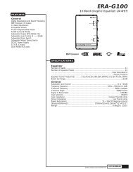
Information Cube<br />
The data acquired in the testing procedure is then graphed<br />
in the form of a 3-dimensional cube, hence the name<br />
PowerCube.<br />
The Phase Angle is expressed on the horizontal axis, the<br />
Output Voltage is presented on the vertical axis <strong>and</strong> the<br />
Impedance is displayed on the Z axis. Output Power, in<br />
watts, is listed on the left h<strong>and</strong> side for each impedance at<br />
1 each phase angle.
I<br />
What is an <strong>Amplifier</strong>?<br />
An amplifier by definition is a voltage generating device,<br />
recreating the signal input which is identical but in a larger<br />
or amplified form. It will be connected to a reactive load<br />
(the speaker). The impedance of this load <strong>and</strong> the phase<br />
of the signal passing through the load will vary, dependent<br />
upon the frequency <strong>and</strong> amplitude of the input signal<br />
(music).<br />
Therefore, a perfect amplifier will be able to maintain the<br />
same output voltage regardless of load characteristics<br />
<strong>and</strong> will not alter the signal it is reproducing. A perfect<br />
amplifier when measured by the Audio Graph PowerCube<br />
would present data that forms a perfect cube. Unfortunately,<br />
amplifiers are not perfect. The laws of physics<br />
generally prevent it. A great amplifier is about the best one<br />
can hope to attain.<br />
As you can see by the PowerCube <strong>and</strong> as you will<br />
experience by listening, your <strong>Series</strong> 1 amplifier is a GREAT<br />
AMPLIFIER!<br />
27
WARRANTY INFORMATION<br />
Rockford Fosgate warrants all electronics to the original consumer/purchaser<br />
to be free from defects in materials or workmanship for a period of three (3)<br />
Years. We will cover parts <strong>and</strong> labor provided the product was purchased from<br />
an Authorized Rockford Fosgate Dealer. This warranty does not apply to any<br />
product on which the seals <strong>and</strong>/or serial number have been broken, removed,<br />
tampered with, defaced or altered in any manner. This warranty applies only<br />
to the original consumer/purchaser <strong>and</strong> is not transferable.<br />
Electronics found to be defective during the warranty period will be repaired or<br />
replaced at Rockford Fosgate’s discretion. Repaired or replaced electronics<br />
will be covered by the balance of the original warranty period only. Rockford<br />
Fosgate shall not be responsible for any incidental or consequential damages<br />
resulting from a defect in electronics. Some states do not allow the exclusion<br />
or limitation of incidental or consequential damages, so the previous limitation<br />
may not be applicable.<br />
The warranty does not cover any appearance item, any cost or expense related<br />
to the removal or reinstallation of the product, any accessory used in conjunction<br />
with the product, damage to the product resulting from alteration, accident,<br />
misuse or abuse, or improper installation. This warranty does not apply if the<br />
parts or labor, which would otherwise be provided without charge under this<br />
warranty, are obtained from any source other than Rockford Fosgate or an<br />
Authorized Rockford Fosgate Service Center.<br />
This warranty is the only express warranty <strong>and</strong> does not create any implied<br />
warranties. Rockford Fosgate limits its obligations under any implied warranties<br />
under state laws to a period not to exceed the written warranty period. Some<br />
states do not allow limitation on how long an implied warranty lasts, so the above<br />
limitation may not apply. This warranty applies only to products sold in the<br />
United States of America or its possessions. For warranty outside the U.S.A.,<br />
please contact the nearest Authorized Rockford Fosgate Dealer. This warranty<br />
gives the consumer specific legal rights, <strong>and</strong> the consumer may have other<br />
rights which vary from state to state.<br />
A defective product must be shipped prepaid to the Authorized Rockford<br />
Fosgate Dealer from which the consumer purchased the product or to the<br />
Rockford Fosgate factory in Tempe, Arizona in the original factory carton or<br />
equivalent. Any shipping loss or damage will be borne by the consumer or the<br />
consumer’s shipper. A consumer returning a product to the factory should call<br />
(800) 663-9899 for a Return Authorization Number. All shipments shall be<br />
clearly marked with the Return Authorization Number on the outside of the<br />
shipping carton.<br />
Ship to:<br />
Rockford Corporation<br />
Warranty Repair Department<br />
2055 E. 5th Street<br />
Tempe, AZ 85281 U.S.A.<br />
Return Authorization Number:
REV. B 3/93<br />
MAN-01/91<br />
Rockford Fosgate<br />
A Division of Rockford Corporation<br />
546 South Rockford Drive<br />
Tempe, Arizona 85281 U.S.A.<br />
In U.S.A., (602) 967-3565<br />
In Canada, call Korbon (416) 567-l 929<br />
In Europe, Fax (49) 421-487-877<br />
01993 Rockford Corporation