

Application Note 1853 COT Drivers Control LED Ripple Current
Application Note 1853 COT Drivers Control LED Ripple Current
Application Note 1853 COT Drivers Control LED Ripple Current
- No tags were found...

You also want an ePaper? Increase the reach of your titles
YUMPU automatically turns print PDFs into web optimized ePapers that Google loves.
AN-<strong>1853</strong><br />
isolation and/or power factor correction, the LM3402 or<br />
LM3404 buck regulator could be paired with an existing AC-<br />
DC regulator to provide the 24V, resulting in a high-quality<br />
universal current source.<br />
desired peak-to-peak inductor ripple current, ΔiL. The<br />
required inductance is then:<br />
2. Select the closest standard inductor value to L and call it<br />
L STD . R ON can then be calculated with the following<br />
expression:<br />
30064502<br />
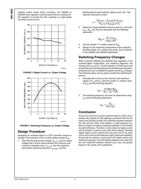
FIGURE 2. <strong>Ripple</strong> <strong>Current</strong> vs. Output Voltage<br />
3. Use the closest 1% resistor value for R ON .<br />
4. Design for the remaining components (input capacitor,<br />
Schottky diode, etc.) remains the same, and is outlined<br />
in the LM3402 and LM3404 datasheets.<br />
Switching Frequency Changes<br />
When using the LM3402 and LM3404 buck regulators in the<br />
constant-ripple configuration, the switching frequency will<br />
change with V IN and V O . Careful attention to PCB layout and<br />
proper filtering must be employed will all switching converters,<br />
and particular care is needed for systems where f SW changes.<br />
The following steps can be used to predict the switching frequency:<br />
1. Calculate the on-time at the minimum and maximum<br />
values of V IN and V O using the actual 1% resistor value<br />
of R ON and the following equation:<br />
2. The switching frequency can then be determined using<br />
t ON and the following expression:<br />
30064503<br />
FIGURE 3. Switching Frequency vs. Output Voltage<br />
Design Procedure<br />
Designing for constant ripple in a <strong>COT</strong> converter requires a<br />
change in the selection of the on-time setting resistor R ON :<br />
1. Start with the typical input voltage, V IN-TYP , and an output<br />
voltage that is at the center between the minimum and<br />
maximum expected value, V O-CTR . Use the maximum<br />
permissible switching frequency, f SW-MAX , and the<br />
Conclusion<br />
A pure DC <strong>LED</strong> drive current would be ideal for <strong>LED</strong>s, but in<br />
practice the majority of <strong>LED</strong> lighting is powered from the AC<br />
mains and includes at least one switching regulator between<br />
the wall and the <strong>LED</strong>s. Even battery or solar-powered systems<br />
are likely to employ a switching regulator in the interest<br />
of power efficiency. Therefore, some amount of ripple current<br />
will be present in almost every <strong>LED</strong> driver design. Allowing<br />
higher ripple current reduces the size and cost of the drive<br />
circuit, but comes at the expense of light output and reliability.<br />
Armed with the ability to control both <strong>LED</strong> ripple current and<br />
switching frequency, the <strong>LED</strong> lighting designer can make his/<br />
her own trade-offs between solution size, cost, and quality<br />
based on the needs of the application.<br />
www.national.com 2

![P-CAD EDA - [Sheet1]](https://img.yumpu.com/49470492/1/190x115/p-cad-eda-sheet1.jpg?quality=85)


