

Application Note 1853 COT Drivers Control LED Ripple Current
Application Note 1853 COT Drivers Control LED Ripple Current
Application Note 1853 COT Drivers Control LED Ripple Current
- No tags were found...

Create successful ePaper yourself
Turn your PDF publications into a flip-book with our unique Google optimized e-Paper software.
<strong>COT</strong> <strong>Drivers</strong> <strong>Control</strong> <strong>LED</strong><br />
<strong>Ripple</strong> <strong>Current</strong><br />
The constant on-time (<strong>COT</strong>) control method used by the<br />
LM3402 and LM3404 constant-current buck regulators provides<br />
a balance between control over switching frequency<br />
and fast transient response. Normally this "quasi-hysteretic"<br />
control senses the input voltage and adjusts the on-time t ON<br />
of the power MOSFET as needed to keep f SW constant. Investigating<br />
a little more deeply reveals that t ON is in fact<br />
proportional to the current flowing into the R ON pin. The addition<br />
of a single, general purpose PNP transistor forces t ON<br />
to be proportional to (V IN - V O ) and provides two benefits that<br />
are particularly useful to <strong>LED</strong> drivers: improved tolerance of<br />
the average <strong>LED</strong> current, I F , and constant <strong>LED</strong> ripple current,<br />
Δi F .<br />
Benefits of Constant <strong>Ripple</strong><br />
The luminous flux and dominant wavelength (or color temperature<br />
for white <strong>LED</strong>s) of <strong>LED</strong> light are controlled by average<br />
current. The constant-ripple <strong>LED</strong> driver in Figure 1 is<br />
much better at controlling average <strong>LED</strong> current over changes<br />
in both input voltage and changes in output voltage because<br />
it fixes the valley of the inductor current and also fixes the<br />
current ripple.<br />
<strong>Control</strong>ling <strong>LED</strong> ripple current implies control over peak <strong>LED</strong><br />
current, which in turn affects the luminous flux of an <strong>LED</strong>. All<br />
National Semiconductor<br />
<strong>Application</strong> <strong>Note</strong> <strong>1853</strong><br />
Chris Richardson<br />
September 23, 2008<br />
<strong>LED</strong>s have a relationship between their luminous flux and<br />
forward current, I F , that is linear up to a point. Beyond that<br />
point, increasing I F causes more heat than light. High ripple<br />
current forces the <strong>LED</strong> to spend half of the time at a high peak<br />
current, putting it in the lower lm/W region of the flux curve.<br />
This reduces the light output when compared to a purely DC<br />
drive current even though the average forward current remains<br />
the same.<br />
Close inspection of <strong>LED</strong> datasheets also reveals that the absolute<br />
maximum ratings for peak current are close to or often<br />
equal to the ratings for average current. High current density<br />
in the <strong>LED</strong> junction lowers lumen maintenance, providing yet<br />
another incentive for keeping the ripple current under control.<br />
Circuit Performance<br />
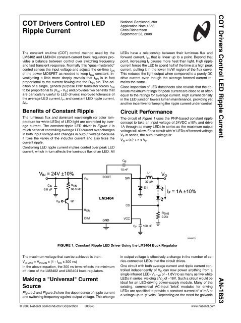
The circuit of Figure 1 uses the PNP-based constant ripple<br />
concept to take an input voltage of 24VDC ±10% and drive<br />
1A through as many <strong>LED</strong>s in series as the maximum output<br />
voltage will allow. For a circuit with 'n' <strong>LED</strong>s of forward voltage<br />
V F in series, the output voltage is:<br />
V O = 0.2 + n x V F<br />
30064501<br />
FIGURE 1. Constant <strong>Ripple</strong> <strong>LED</strong> Driver Using the LM3404 Buck Regulator<br />
The maximum voltage that can be achieved is then:<br />
V O-MAX = V IN-MIN x (1 - f SW x 300 ns)<br />
In the above equation, the 300 ns term reflects the minimum<br />
off -time of the LM3402 and LM3404 buck regulators.<br />
Making a "Universal" <strong>Current</strong><br />
Source<br />
Figure 2 and Figure 3 show the dependence of ripple current<br />
and switching frequency against output voltage. This change<br />
in output voltage is effectively a change in the number of series-connected<br />
<strong>LED</strong>s that the circuit drives.<br />
One circuit with both average current and ripple current controlled<br />
independently of V O can now power anything from a<br />
single infrared <strong>LED</strong> (V F-TYP of ~1.8V) to as many as five white<br />
<strong>LED</strong>s in series, yielding a V O of ~18V. Such a circuit would be<br />
ideal for an <strong>LED</strong>-driving power-supply module. Many of the<br />
existing, commercial AC-input 'brick' modules for driving<br />
<strong>LED</strong>s are specified to provide a constant current of 'x' mA at<br />
a voltage up to 'y' volts. Depending on the need for galvanic<br />
© 2008 National Semiconductor Corporation 300645 www.national.com<br />
<strong>COT</strong> <strong>Drivers</strong> <strong>Control</strong> <strong>LED</strong> <strong>Ripple</strong> <strong>Current</strong> AN-<strong>1853</strong>
AN-<strong>1853</strong><br />
isolation and/or power factor correction, the LM3402 or<br />
LM3404 buck regulator could be paired with an existing AC-<br />
DC regulator to provide the 24V, resulting in a high-quality<br />
universal current source.<br />
desired peak-to-peak inductor ripple current, ΔiL. The<br />
required inductance is then:<br />
2. Select the closest standard inductor value to L and call it<br />
L STD . R ON can then be calculated with the following<br />
expression:<br />
30064502<br />
FIGURE 2. <strong>Ripple</strong> <strong>Current</strong> vs. Output Voltage<br />
3. Use the closest 1% resistor value for R ON .<br />
4. Design for the remaining components (input capacitor,<br />
Schottky diode, etc.) remains the same, and is outlined<br />
in the LM3402 and LM3404 datasheets.<br />
Switching Frequency Changes<br />
When using the LM3402 and LM3404 buck regulators in the<br />
constant-ripple configuration, the switching frequency will<br />
change with V IN and V O . Careful attention to PCB layout and<br />
proper filtering must be employed will all switching converters,<br />
and particular care is needed for systems where f SW changes.<br />
The following steps can be used to predict the switching frequency:<br />
1. Calculate the on-time at the minimum and maximum<br />
values of V IN and V O using the actual 1% resistor value<br />
of R ON and the following equation:<br />
2. The switching frequency can then be determined using<br />
t ON and the following expression:<br />
30064503<br />
FIGURE 3. Switching Frequency vs. Output Voltage<br />
Design Procedure<br />
Designing for constant ripple in a <strong>COT</strong> converter requires a<br />
change in the selection of the on-time setting resistor R ON :<br />
1. Start with the typical input voltage, V IN-TYP , and an output<br />
voltage that is at the center between the minimum and<br />
maximum expected value, V O-CTR . Use the maximum<br />
permissible switching frequency, f SW-MAX , and the<br />
Conclusion<br />
A pure DC <strong>LED</strong> drive current would be ideal for <strong>LED</strong>s, but in<br />
practice the majority of <strong>LED</strong> lighting is powered from the AC<br />
mains and includes at least one switching regulator between<br />
the wall and the <strong>LED</strong>s. Even battery or solar-powered systems<br />
are likely to employ a switching regulator in the interest<br />
of power efficiency. Therefore, some amount of ripple current<br />
will be present in almost every <strong>LED</strong> driver design. Allowing<br />
higher ripple current reduces the size and cost of the drive<br />
circuit, but comes at the expense of light output and reliability.<br />
Armed with the ability to control both <strong>LED</strong> ripple current and<br />
switching frequency, the <strong>LED</strong> lighting designer can make his/<br />
her own trade-offs between solution size, cost, and quality<br />
based on the needs of the application.<br />
www.national.com 2
BOM<br />
ID Part Number Type Size Parameters Qty Vendor<br />
U1 LM3404 <strong>LED</strong> Driver SO-8 42V, 1.2A 1 NSC<br />
Q1 CMPT3906 PNP SOT23-6 40 V CE , 10 mA 1 Central Semi<br />
L1 VLF10040T-330M2R1 Inductor 10 x 10 x 4.0 mm 33 µH, 2.1A, 80 Ω 1 TDK<br />
D1 CMSH2-40M Schottky Diode SMA 40V, 2A 1 Central Semi<br />
C F VJ0603Y104KXXAT Capacitor 0603 100 nF, 10% 1 Vishay<br />
C B VJ0603Y103KXXAT Capacitor 0603 10 nF, 10% 1 Vishay<br />
C IN C4532X7R1H685M Capacitor 1812 6.8 µF, 50V 1 TDK<br />
R SNS ERJ8RQFR20V Resistor 1206 0.2Ω, 1% 1 Panasonic<br />
R ON CRCW06035762F Resistor 0603 57.6 kΩ, 1% 1 Vishay<br />
AN-<strong>1853</strong><br />
3 www.national.com
AN-<strong>1853</strong> <strong>COT</strong> <strong>Drivers</strong> <strong>Control</strong> <strong>LED</strong> <strong>Ripple</strong> <strong>Current</strong><br />
<strong>Note</strong>s<br />
For more National Semiconductor product information and proven design tools, visit the following Web sites at:<br />
Products<br />
Design Support<br />
Amplifiers www.national.com/amplifiers WEBENCH www.national.com/webench<br />
Audio www.national.com/audio Analog University www.national.com/AU<br />
Clock Conditioners www.national.com/timing App <strong>Note</strong>s www.national.com/appnotes<br />
Data Converters www.national.com/adc Distributors www.national.com/contacts<br />
Displays www.national.com/displays Green Compliance www.national.com/quality/green<br />
Ethernet www.national.com/ethernet Packaging www.national.com/packaging<br />
Interface www.national.com/interface Quality and Reliability www.national.com/quality<br />
LVDS www.national.com/lvds Reference Designs www.national.com/refdesigns<br />
Power Management www.national.com/power Feedback www.national.com/feedback<br />
Switching Regulators www.national.com/switchers<br />
LDOs www.national.com/ldo<br />
<strong>LED</strong> Lighting www.national.com/led<br />
PowerWise www.national.com/powerwise<br />
Serial Digital Interface (SDI) www.national.com/sdi<br />
Temperature Sensors www.national.com/tempsensors<br />
Wireless (PLL/VCO) www.national.com/wireless<br />
THE CONTENTS OF THIS DOCUMENT ARE PROVIDED IN CONNECTION WITH NATIONAL SEMICONDUCTOR CORPORATION<br />
(“NATIONAL”) PRODUCTS. NATIONAL MAKES NO REPRESENTATIONS OR WARRANTIES WITH RESPECT TO THE ACCURACY<br />
OR COMPLETENESS OF THE CONTENTS OF THIS PUBLICATION AND RESERVES THE RIGHT TO MAKE CHANGES TO<br />
SPECIFICATIONS AND PRODUCT DESCRIPTIONS AT ANY TIME WITHOUT NOTICE. NO LICENSE, WHETHER EXPRESS,<br />
IMPLIED, ARISING BY ESTOPPEL OR OTHERWISE, TO ANY INTELLECTUAL PROPERTY RIGHTS IS GRANTED BY THIS<br />
DOCUMENT.<br />
TESTING AND OTHER QUALITY CONTROLS ARE USED TO THE EXTENT NATIONAL DEEMS NECESSARY TO SUPPORT<br />
NATIONAL’S PRODUCT WARRANTY. EXCEPT WHERE MANDATED BY GOVERNMENT REQUIREMENTS, TESTING OF ALL<br />
PARAMETERS OF EACH PRODUCT IS NOT NECESSARILY PERFORMED. NATIONAL ASSUMES NO LIABILITY FOR<br />
APPLICATIONS ASSISTANCE OR BUYER PRODUCT DESIGN. BUYERS ARE RESPONSIBLE FOR THEIR PRODUCTS AND<br />
APPLICATIONS USING NATIONAL COMPONENTS. PRIOR TO USING OR DISTRIBUTING ANY PRODUCTS THAT INCLUDE<br />
NATIONAL COMPONENTS, BUYERS SHOULD PROVIDE ADEQUATE DESIGN, TESTING AND OPERATING SAFEGUARDS.<br />
EXCEPT AS PROVIDED IN NATIONAL’S TERMS AND CONDITIONS OF SALE FOR SUCH PRODUCTS, NATIONAL ASSUMES NO<br />
LIABILITY WHATSOEVER, AND NATIONAL DISCLAIMS ANY EXPRESS OR IMPLIED WARRANTY RELATING TO THE SALE<br />
AND/OR USE OF NATIONAL PRODUCTS INCLUDING LIABILITY OR WARRANTIES RELATING TO FITNESS FOR A PARTICULAR<br />
PURPOSE, MERCHANTABILITY, OR INFRINGEMENT OF ANY PATENT, COPYRIGHT OR OTHER INTELLECTUAL PROPERTY<br />
RIGHT.<br />
LIFE SUPPORT POLICY<br />
NATIONAL’S PRODUCTS ARE NOT AUTHORIZED FOR USE AS CRITICAL COMPONENTS IN LIFE SUPPORT DEVICES OR<br />
SYSTEMS WITHOUT THE EXPRESS PRIOR WRITTEN APPROVAL OF THE CHIEF EXECUTIVE OFFICER AND GENERAL<br />
COUNSEL OF NATIONAL SEMICONDUCTOR CORPORATION. As used herein:<br />
Life support devices or systems are devices which (a) are intended for surgical implant into the body, or (b) support or sustain life and<br />
whose failure to perform when properly used in accordance with instructions for use provided in the labeling can be reasonably expected<br />
to result in a significant injury to the user. A critical component is any component in a life support device or system whose failure to perform<br />
can be reasonably expected to cause the failure of the life support device or system or to affect its safety or effectiveness.<br />
National Semiconductor and the National Semiconductor logo are registered trademarks of National Semiconductor Corporation. All other<br />
brand or product names may be trademarks or registered trademarks of their respective holders.<br />
Copyright© 2008 National Semiconductor Corporation<br />
For the most current product information visit us at www.national.com<br />
www.national.com<br />
National Semiconductor<br />
Americas Technical<br />
Support Center<br />
Email: support@nsc.com<br />
Tel: 1-800-272-9959<br />
National Semiconductor Europe<br />
Technical Support Center<br />
Email: europe.support@nsc.com<br />
German Tel: +49 (0) 180 5010 771<br />
English Tel: +44 (0) 870 850 4288<br />
National Semiconductor Asia<br />
Pacific Technical Support Center<br />
Email: ap.support@nsc.com<br />
National Semiconductor Japan<br />
Technical Support Center<br />
Email: jpn.feedback@nsc.com

![P-CAD EDA - [Sheet1]](https://img.yumpu.com/49470492/1/190x115/p-cad-eda-sheet1.jpg?quality=85)


