A coaxial HOM coupler for a superconducting RF cavity and its low ...
A coaxial HOM coupler for a superconducting RF cavity and its low ...
A coaxial HOM coupler for a superconducting RF cavity and its low ...

Create successful ePaper yourself
Turn your PDF publications into a flip-book with our unique Google optimized e-Paper software.
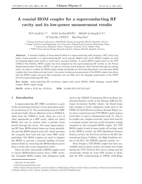
CPC(HEP & NP), 2011, 35(3): 301–307 Chinese Physics C Vol. 35, No. 3, Mar., 2011<br />
A <strong>coaxial</strong> <strong>HOM</strong> <strong>coupler</strong> <strong>for</strong> a <strong>superconducting</strong> <strong>RF</strong><br />
<strong>cavity</strong> <strong>and</strong> <strong>its</strong> <strong>low</strong>-power measurement results<br />
SUN An() 1,4;1) TANG Ya-Zhe() 2 ZHANG Li-Ping() 3<br />
LI Ying-Min () 4 Han-Sung Kim 4<br />
1 Pohang Accelerator Laboratory, POSTECH, Pohang, Kyung-Buk 790-784, Republic of Korea<br />
2 College of Science <strong>and</strong> Engineering, City University of Hong Kong, Kowloon, Hong Kong, China<br />
3 Construction Machinery School, Chang’an University, Xi’an 710064, China<br />
4 PEFP, Korea Atomic Energy Research Institute, Daejeon 305-353, Republic of Korea<br />
Abstract: A resonant buildup of beam-induced fields in a <strong>superconducting</strong> radio frequency (<strong>RF</strong>) <strong>cavity</strong> may<br />
make a beam unstable or a <strong>superconducting</strong> <strong>RF</strong> <strong>cavity</strong> quench. Higher-order mode (<strong>HOM</strong>) <strong>coupler</strong>s are used<br />
<strong>for</strong> damping higher-order modes to avoid such a resonant buildup. A <strong>coaxial</strong> <strong>HOM</strong> <strong>coupler</strong> based on the TTF<br />
(TESLA Test Facility) <strong>HOM</strong> <strong>coupler</strong> has been designed <strong>for</strong> the <strong>superconducting</strong> <strong>RF</strong> cavities at the Proton<br />
Engineering Frontier Project (PEFP) in order to overcome notch frequency shift <strong>and</strong> feed-through tip melting<br />
issues. In order to confirm the <strong>HOM</strong> <strong>coupler</strong> design <strong>and</strong> finalize <strong>its</strong> structural dimensions, two prototype <strong>HOM</strong><br />
<strong>coupler</strong>s have been fabricated <strong>and</strong> tested. Low-power testing <strong>and</strong> measurement of the <strong>HOM</strong> <strong>coupler</strong>s has shown<br />
that the <strong>HOM</strong> <strong>coupler</strong> has good filter properties <strong>and</strong> can fully meet the damping requirements of the PEFP<br />
<strong>low</strong>-beta <strong>superconducting</strong> <strong>RF</strong> linac.<br />
Key words: <strong>superconducting</strong> <strong>RF</strong> accelerator, higher-order mode (<strong>HOM</strong>), <strong>HOM</strong> damping, <strong>coaxial</strong> <strong>HOM</strong><br />
<strong>coupler</strong>, <strong>HOM</strong> <strong>coupler</strong> design<br />
PACS: 84.90.-a, 85.25.Am, 42.79.Gn DOI: 10.1088/1674-1137/35/3/017<br />
1 Introduction<br />
A <strong>superconducting</strong> <strong>RF</strong> (S<strong>RF</strong>) accelerator is part<br />
of the accelerating structure of new-generation particle<br />
accelerators [1–5]. The accelerating mode of a S<strong>RF</strong><br />
accelerator built with an elliptical <strong>cavity</strong> is TM010 π.<br />
Aside from the TM010 π mode, there are a lot of<br />
other eigenmodes in a S<strong>RF</strong> <strong>cavity</strong>, which are called<br />
<strong>HOM</strong>s <strong>and</strong> can be excited when a particle beam<br />
travels through the <strong>cavity</strong>. The main <strong>superconducting</strong><br />
<strong>RF</strong> linac <strong>HOM</strong>-related issues are beam instabilities<br />
<strong>and</strong> the <strong>HOM</strong>-induced power [6], which increases<br />
the cryogenic heat load <strong>and</strong> may cause S<strong>RF</strong> <strong>cavity</strong><br />
quenching. The <strong>HOM</strong> <strong>coupler</strong>s are used to dampen<br />
the <strong>HOM</strong>s to prevent a resonant buildup of beaminduced<br />
fields by extracting the <strong>HOM</strong>-induced power<br />
from a <strong>cavity</strong> into room temperature loads.<br />
There are three main kinds of <strong>HOM</strong> <strong>coupler</strong>s used<br />
to remove <strong>HOM</strong>-induced power from a S<strong>RF</strong> <strong>cavity</strong>:<br />
the waveguide <strong>HOM</strong> <strong>coupler</strong> with dissipative loads<br />
used in the CEBAF (Continuous Electron Beam Accelerator<br />
Facility) <strong>cavity</strong> at the Thomas Jefferson National<br />
Accelerator Facility (JLab), the fluted beam<br />
tube leading to ferrite dissipative loads used at the<br />
CESR (Cornell Electron-positron Storage Ring) <strong>cavity</strong><br />
<strong>and</strong> a <strong>coaxial</strong> loop-type TTF <strong>HOM</strong> <strong>coupler</strong> using a<br />
notch filter to reject a fundamental mode [7]. Due to<br />
<strong>its</strong> smaller size, simpler structure, <strong>low</strong>er heat load <strong>for</strong><br />
a cryogenic system <strong>and</strong> easy notch frequency tuning<br />
compared to the waveguide <strong>HOM</strong> <strong>coupler</strong>, the TTF<br />
<strong>HOM</strong> <strong>coupler</strong> is used in many multi-cell cavities, such<br />
as the TESLA cavities, the SNS (Spallation Neutron<br />
Source) cavities, the Low Loss cavities at the ILC (International<br />
Linear Collider), the High Gradient cavities<br />
at the ILC, the CEBAF upgrade cavities, etc.<br />
Even though a TTF <strong>HOM</strong> <strong>coupler</strong> has been successfully<br />
used on many cavities, two faults were found<br />
during the VTA (Vertical Test Area) testing <strong>and</strong> the<br />
cryomodule testing <strong>for</strong> some SNS cavities at JLab,<br />
<strong>and</strong> the SNS commissioning at ORNL (Oak Ridge<br />
Received 16 June 2010<br />
1) E-mail: sun ancn@yahoo.com<br />
©2011 Chinese Physical Society <strong>and</strong> the Institute of High Energy Physics of the Chinese Academy of Sciences <strong>and</strong> the Institute<br />
of Modern Physics of the Chinese Academy of Sciences <strong>and</strong> IOP Publishing Ltd
302 Chinese Physics C (HEP & NP) Vol. 35<br />
National Laboratory): notch frequency shift <strong>and</strong><br />
melting of the capacitive coupling copper feedthrough<br />
tip. These faults caused two SNS S<strong>RF</strong> cavities<br />
to become unpowered <strong>and</strong> ten SNS S<strong>RF</strong> cavities<br />
to operate at a reduced gradient [8–10]. JLab tried to<br />
change the copper feed-through into a niobium feedthrough<br />
in a Renascence Cryomodule. The test results<br />
were that a quenching happened instead of the<br />
tip melting.<br />
A <strong>low</strong>-beta <strong>superconducting</strong> <strong>RF</strong> <strong>cavity</strong> (β g =0.42)<br />
is being considered in order to accelerate a proton<br />
beam at 700 MHz in the PEFP linac <strong>and</strong> <strong>its</strong> extended<br />
project [11–15]. <strong>HOM</strong> analysis of the PEFP <strong>low</strong>-beta<br />
cavities shows that the <strong>HOM</strong> <strong>coupler</strong>’s external quality<br />
factor Q ext is <strong>low</strong>er than 3×10 5 , thus reducing the<br />
influence of dangerous modes on the beam instabilities<br />
<strong>and</strong> the <strong>HOM</strong>-induced power [16]. Table 1 lists<br />
the specifications of the PEFP <strong>HOM</strong> damping.<br />
Table 1. <strong>HOM</strong> <strong>coupler</strong> specifications <strong>for</strong> the<br />
PEFP <strong>low</strong>-beta <strong>cavity</strong>.<br />
parameter<br />
<strong>HOM</strong> damping modes<br />
value<br />
M23, M31, M32,<br />
M33, D11, D32*<br />
Q ext <strong>for</strong> <strong>HOM</strong> damping mode 3×10 5<br />
<strong>HOM</strong> average <strong>RF</strong> load<br />
1.0 W<br />
Q ext <strong>for</strong> TM010 π mode 6.26×10 10<br />
fundamental π mode <strong>RF</strong> load at<br />
E acc=8 MV/m (in a macro-pulse)<br />
10 W<br />
*Here, ‘Mm’ <strong>and</strong> ‘Dm’ mean the m-th mode of the monopole<br />
<strong>and</strong> the dipole of the MAFIA calculation, respectively.<br />
In order to satisfy the PEFP <strong>HOM</strong> damping requirements,<br />
<strong>and</strong> to avoid the shortcomings of the<br />
TTF <strong>HOM</strong> <strong>coupler</strong>, a new <strong>coaxial</strong> <strong>HOM</strong> <strong>coupler</strong><br />
with one hook <strong>and</strong> two rods has been designed <strong>for</strong><br />
the PEFP S<strong>RF</strong> cavities. This <strong>coupler</strong> can satisfy the<br />
<strong>HOM</strong> damping requirements of the PEFP S<strong>RF</strong> linac<br />
<strong>and</strong> has a good filter property, <strong>low</strong> electromagnetic<br />
fields at the inner conductor ends <strong>and</strong> it is easy to<br />
tune <strong>and</strong> control a notch frequency. In order to confirm<br />
the <strong>HOM</strong> <strong>coupler</strong> design <strong>and</strong> finalize the inner<br />
conductor penetration depth <strong>and</strong> angle between the<br />
<strong>cavity</strong> axis <strong>and</strong> the hook of the inner conductor, two<br />
prototype <strong>HOM</strong> <strong>coupler</strong>s have been fabricated <strong>and</strong><br />
tested with a copper prototype <strong>cavity</strong>. The testing<br />
<strong>and</strong> measurements of the <strong>HOM</strong> <strong>coupler</strong>s have shown<br />
that the new <strong>HOM</strong> <strong>coupler</strong> can fully meet the damping<br />
requirements of the PEFP <strong>low</strong>-beta <strong>superconducting</strong><br />
<strong>RF</strong> linac. Based on the test results, the final<br />
dimensions of the <strong>HOM</strong> <strong>coupler</strong>s have been determined.<br />
2 PEFP <strong>HOM</strong> <strong>coupler</strong> design<br />
Figure 1 shows a TTF <strong>coaxial</strong> <strong>HOM</strong> <strong>coupler</strong> <strong>for</strong><br />
the SNS cavities [8, 17]. The <strong>HOM</strong>-induced power<br />
is coupled out by a coupling capacitance, which is a<br />
gap of about 0.76 mm composed of a feed-through tip<br />
<strong>and</strong> a cutting flat face on the inner conductor. The<br />
3-D simulation showed that there was a high electromagnetic<br />
field in the coupling capacitance gap. After<br />
high power measurements in the VTA at JLab, tip<br />
melting in some of the cavities was observed. Because<br />
the <strong>HOM</strong> <strong>coupler</strong> 2 is located opposite the<br />
fundamental power <strong>coupler</strong> (FPC), the melted tip<br />
could drop onto the FPC inner conductor or window,<br />
<strong>and</strong> create big bursts of gas in the FPC, which<br />
causes vacuum-related interlock trips. In addition,<br />
the melted tip could become welded to the inner conductor,<br />
this results in excessive fundamental power<br />
coupled through the <strong>HOM</strong> signal. These vacuumrelated<br />
interlock trips <strong>and</strong> the excessive fundamental<br />
power coupled through the <strong>HOM</strong> signal were observed<br />
during SNS SCL commissioning. The excessive fundamental<br />
power coupling caused two SNS cavities to<br />
be unpowered [10].<br />
Fig. 1.<br />
SNS <strong>HOM</strong> <strong>coupler</strong> scheme.<br />
The notch frequency is controlled by adjusting the<br />
notch frequency filter capacitance, which is a gap of<br />
about 0.53 mm between the inner conductor end <strong>and</strong><br />
the outer conductor cover. For the SNS prototype<br />
cavities <strong>and</strong> the first medium-beta cryomodules, by<br />
pulling or pushing the nipple on the outer conductor<br />
to obtain a physical de<strong>for</strong>mation <strong>and</strong> to setup<br />
notch frequency, after cooling down the cryomodules,<br />
due to thermal shrinkage of the outer conductor, the<br />
physical de<strong>for</strong>mation was lost. Finally, the notch frequency<br />
shifted <strong>for</strong> some <strong>HOM</strong> <strong>coupler</strong>s. From the second<br />
medium-beta cryomodules, a one-direction locker<br />
was used to fix the notch frequency by holding the<br />
nipple, the results were that the notch frequency of
No. 3 SUN An et al: A <strong>coaxial</strong> <strong>HOM</strong> <strong>coupler</strong> <strong>for</strong> a <strong>superconducting</strong> <strong>RF</strong> <strong>cavity</strong> <strong>and</strong> <strong>its</strong> <strong>low</strong>-power measurement results 303<br />
some <strong>HOM</strong> <strong>coupler</strong>s was fixed, but some <strong>HOM</strong> <strong>coupler</strong>s<br />
had shifted. This notch frequency shift results in<br />
abnormal fundamental frequency signals being transmitted<br />
through the <strong>HOM</strong> <strong>coupler</strong>s, which was observed<br />
during cryomodule testing in the test cave at<br />
JLab, <strong>and</strong> also in the SNS tunnel during the SCL<br />
commissioning, <strong>and</strong> caused 10 SNS cavities to operate<br />
at reduced gradients <strong>and</strong>/or repetition rates [10].<br />
In order to avoid the same disasters in the PEFP<br />
<strong>HOM</strong> <strong>coupler</strong>s, a new type of <strong>coaxial</strong> <strong>HOM</strong> <strong>coupler</strong><br />
needs to be designed <strong>for</strong> the PEFP cavities. The new<br />
<strong>coupler</strong> should meet the PEFP <strong>HOM</strong> damping requirements,<br />
the notch frequency shift should be easily<br />
controlled <strong>and</strong> melting of the feed-through tip should<br />
be eradicated.<br />
2.1 <strong>HOM</strong> <strong>coupler</strong> structure<br />
The PEFP <strong>HOM</strong> <strong>coupler</strong> design is based on the<br />
TTF type <strong>coaxial</strong> <strong>HOM</strong> <strong>coupler</strong>, as shown in Fig. 2.<br />
The feed-through <strong>for</strong> coupling out the <strong>HOM</strong> induced<br />
power is directly installed on the inner conductor in<br />
order to avoid the feed-through tip melting, as observed<br />
in the SNS <strong>HOM</strong> <strong>coupler</strong>s. Two stubs are<br />
used to adjust the notch frequency <strong>and</strong> to optimize<br />
the electro-magnetic distribution during the <strong>coupler</strong><br />
3-D design. The rod of the inner conductor is used<br />
to couple the electric components of the <strong>HOM</strong>s <strong>and</strong><br />
the hook of the inner conductor is used to couple the<br />
magnetic components of the <strong>HOM</strong>s.<br />
directions, this tuner can tune the notch frequency in<br />
both directions.<br />
The outer conductor, the inner conductor <strong>and</strong> the<br />
feed-through are made of a high RRR niobium (Nb).<br />
Because NbTi alloy has almost the same thermal<br />
properties as Nb, but has better mechanical properties<br />
than pure Nb, we chose NbTi alloy to fabricate<br />
the notch frequency tuner <strong>and</strong> the flange of the feedthough<br />
of the <strong>coupler</strong>.<br />
2.2 <strong>HOM</strong> <strong>coupler</strong> optimization<br />
The basic rules to optimize the <strong>coaxial</strong> <strong>HOM</strong> <strong>coupler</strong><br />
are:<br />
a) The notch frequency is the <strong>cavity</strong> operating frequency.<br />
b) The notch of the operating frequency should<br />
be as deep as possible.<br />
c) Filter notch frequency sensitivity should be as<br />
<strong>low</strong> as possible.<br />
d) There should be a uni<strong>for</strong>m electric field or magnetic<br />
field in the <strong>coupler</strong>.<br />
e) Notch frequency can be easily tuned <strong>and</strong> controlled.<br />
Normally we use an out-coupled power with dB<br />
to evaluate the filter properties of a <strong>HOM</strong> <strong>coupler</strong>.<br />
Based on the above rules, we simulated the outcoupled<br />
power <strong>for</strong> different angles between two rods,<br />
<strong>and</strong> <strong>for</strong> different distances between two rods, between<br />
the up-rod <strong>and</strong> the filter end, between the down-rod<br />
<strong>and</strong> the inner conductor head, <strong>and</strong> <strong>for</strong> different hook<br />
shapes, as well as <strong>for</strong> various outer conductor diameters<br />
<strong>and</strong> inner conductor positions <strong>and</strong> diameters by<br />
using a 3-D MicroWave Studio (MWS)[18]. According<br />
to the simulation results of the out-coupled power<br />
Fig. 2.<br />
A cutaway of a 3-D PEFP <strong>HOM</strong> <strong>coupler</strong>.<br />
Based on the tuning <strong>and</strong> operating experiences of<br />
the SNS <strong>HOM</strong> <strong>coupler</strong>s, a nut-type notch frequency<br />
tuner was designed <strong>for</strong> the PEFP <strong>HOM</strong> <strong>coupler</strong>s. The<br />
tuner holds the nipple on the outer conductor of the<br />
<strong>HOM</strong> <strong>coupler</strong>. By screwing the nut-tuner, the gap<br />
of the notch frequency filter capacitance is changed<br />
causing the the notch frequency filter capacitance to<br />
be changed. Because the nut can be screwed in two<br />
Fig. 3.<br />
A MWS mode of a PEFP <strong>HOM</strong> <strong>coupler</strong>.
304 Chinese Physics C (HEP & NP) Vol. 35<br />
<strong>and</strong> by considering the <strong>cavity</strong> space <strong>for</strong> the <strong>HOM</strong> <strong>coupler</strong><br />
installation <strong>and</strong> <strong>HOM</strong> <strong>coupler</strong> fabrication difficulty,<br />
we finalized an optimized <strong>HOM</strong> <strong>coupler</strong> structure<br />
simulation, as shown in Fig. 3. The filter notch<br />
sensitivity of the PEFP <strong>coupler</strong> is 105 MHz/mm,<br />
which is 46% <strong>low</strong>er than that of 226 MHz/mm found<br />
in the SNS <strong>HOM</strong> <strong>coupler</strong>s.<br />
Figure 4 shows the out-coupled power curves of<br />
the PEFP <strong>and</strong> SNS <strong>HOM</strong> <strong>coupler</strong>s. Fig. 4 reveals<br />
that the PEFP <strong>HOM</strong> <strong>coupler</strong> has only one deepest<br />
notch <strong>and</strong> the same out-coupled power as that of the<br />
SNS <strong>HOM</strong> <strong>coupler</strong>.<br />
cause S<strong>RF</strong> <strong>cavity</strong> quenching or unpowered cavities,<br />
such as found with the SNS <strong>HOM</strong> <strong>coupler</strong>s. There<strong>for</strong>e,<br />
we need concentrate on reducing the EM field on<br />
the inner <strong>and</strong> outer conductors’ surface during their<br />
design. A 3-D MWS <strong>cavity</strong> with two <strong>HOM</strong> <strong>coupler</strong>s, a<br />
fundamental power <strong>coupler</strong> (FPC) <strong>and</strong> a field probe<br />
were used to simulate the EM field distribution in<br />
the <strong>cavity</strong> <strong>and</strong> in the <strong>coupler</strong>s. In the simulation, two<br />
<strong>HOM</strong> <strong>coupler</strong>s were installed on a PEFP S<strong>RF</strong> <strong>cavity</strong><br />
with a relative azimuthal angle of about 90 ◦ to<br />
ensure damping of both polarizations of the dipole<br />
modes. One <strong>coupler</strong> was attached to each end of the<br />
<strong>cavity</strong>, as shown in Fig. 5.<br />
Fig. 5. A 3-D MWS mode of a PEFP <strong>low</strong>-beta<br />
<strong>cavity</strong> with two <strong>HOM</strong> <strong>coupler</strong>s, an FPC <strong>and</strong><br />
a field probe.<br />
Fig. 4. Out-coupled power comparison between<br />
a PEFP <strong>HOM</strong> <strong>coupler</strong> <strong>and</strong> an SNS <strong>HOM</strong> <strong>coupler</strong>.<br />
Unsuitable strong electromagnetic (EM) field distribution<br />
of the TM010 π mode in a <strong>HOM</strong> <strong>coupler</strong><br />
could induce strong electric field emission from the<br />
inner conductor surface, multipacting in the <strong>coupler</strong><br />
<strong>and</strong> an electron load in the capacitive gaps that could<br />
Table 2 lists the simulation results of the maximum<br />
EM fields on the <strong>cavity</strong> surface, on the FPC<br />
head <strong>and</strong> on different parts of the <strong>HOM</strong> <strong>coupler</strong>s of<br />
a PEFP S<strong>RF</strong> <strong>low</strong>-beta <strong>cavity</strong> <strong>and</strong> an SNS mediumbeta<br />
<strong>cavity</strong>. The results show that the maximum EM<br />
fields in the PEFP <strong>HOM</strong> <strong>coupler</strong> are approximately<br />
one tenth that of the fields in the SNS medium-beta<br />
<strong>cavity</strong> at the same peak surface electric field on the<br />
cavities.<br />
Table 2. The electromagnetic fields in the SNS <strong>HOM</strong> <strong>coupler</strong> <strong>and</strong> the PEFP <strong>HOM</strong> <strong>coupler</strong> at the same <strong>cavity</strong><br />
surface peak electric field.<br />
position<br />
SNS<br />
PEFP<br />
E/(V/m) H/(A/m) E/(V/m) H/(A/m)<br />
<strong>cavity</strong> surface 1.00×10 7 1.85×10 4 1.00×10 7 1.51×10 4<br />
FPC head 8.65×10 5 697 4.54×10 5 946<br />
<strong>HOM</strong> <strong>coupler</strong> inner conductor head 3.29×10 6 1863 5.30×10 5 575<br />
<strong>HOM</strong> <strong>coupler</strong> inner conductor top 1.25×10 6 0 9.93×10 4 0<br />
<strong>HOM</strong> <strong>coupler</strong> feed-through tip 5.81×10 4 1128 N/A N/A<br />
3 Prototype <strong>HOM</strong> <strong>coupler</strong><br />
After <strong>HOM</strong> analysis of the PEFP <strong>low</strong>-beta cavities,<br />
specifications <strong>for</strong> the PEFP <strong>HOM</strong> <strong>coupler</strong>s were<br />
obtained [15]. In order to confirm the <strong>HOM</strong> <strong>coupler</strong><br />
design, to finalize <strong>its</strong> inner conductor penetration<br />
depth <strong>and</strong> <strong>its</strong> angle between the <strong>cavity</strong> axis <strong>and</strong><br />
the hook of the inner conductor, <strong>and</strong> to analyze the<br />
PEFP <strong>HOM</strong> damping results, two prototype <strong>HOM</strong><br />
<strong>coupler</strong>s were fabricated. A copper prototype <strong>cavity</strong><br />
with two <strong>HOM</strong> ports with a relative azimuthal angle<br />
of about 90 ◦ was fabricated, <strong>and</strong> tuned to produce a
No. 3 SUN An et al: A <strong>coaxial</strong> <strong>HOM</strong> <strong>coupler</strong> <strong>for</strong> a <strong>superconducting</strong> <strong>RF</strong> <strong>cavity</strong> <strong>and</strong> <strong>its</strong> <strong>low</strong>-power measurement results 305<br />
field flatness of 1.43% at 700 MHz [19].<br />
Figure 6 shows the <strong>HOM</strong> <strong>coupler</strong> prototype. A<br />
flange with three 60 ◦ circular slotted holes on the<br />
<strong>HOM</strong> <strong>coupler</strong> body is <strong>for</strong> changing the angle between<br />
the <strong>coupler</strong> hook <strong>and</strong> the beam axis. Each <strong>HOM</strong> port<br />
on a <strong>cavity</strong> beam pipe has a flange with 24 screw holes<br />
that can make a hook angle change with 15 ◦ steps.<br />
Two types of washers with three 60 ◦ circular slotted<br />
holes with a thickness of 0.1 mm <strong>and</strong> 1.0 mm were<br />
inserted between a <strong>coupler</strong> flange <strong>and</strong> a <strong>HOM</strong> port<br />
flange, as shown in Fig. 7. By varying the washer<br />
number, the penetration of an inner conductor of the<br />
<strong>HOM</strong> <strong>coupler</strong> is varied. By changing the relative angle<br />
between the <strong>HOM</strong> <strong>coupler</strong> flange <strong>and</strong> the <strong>HOM</strong><br />
port flange on a <strong>cavity</strong> beam-pipe, the angle between<br />
the hook <strong>and</strong> the beam axis can be varied.<br />
Fig. 6. A PEFP prototype <strong>HOM</strong> <strong>coupler</strong>. (a) the prototype <strong>HOM</strong> <strong>coupler</strong>; (b) the inner conductor <strong>and</strong><br />
feed-through; (c) the vacuum feed-through.<br />
Figure 8 shows a setup to measure the Q ext of the<br />
<strong>HOM</strong> <strong>coupler</strong>s. Two <strong>HOM</strong> <strong>coupler</strong>s were installed on<br />
the prototype <strong>cavity</strong> with washers. We used a network<br />
analyzer to measure the <strong>cavity</strong>-loaded quality<br />
factor Q L <strong>and</strong> the reflected coefficients S11 <strong>and</strong> S22 of<br />
<strong>HOM</strong> <strong>coupler</strong>s 1 <strong>and</strong> 2, <strong>and</strong> we used a Smith chart to<br />
distinguish if the <strong>coupler</strong> was over-coupled or undercoupled<br />
[20]. Then we obtained the coupling coefficients<br />
of the <strong>coupler</strong>s using the fol<strong>low</strong>ing equations:<br />
β e1 = 1+S11 (<strong>for</strong> over-coupled)<br />
1−S11<br />
or<br />
β e1 = 1−S11 (<strong>for</strong> under-<strong>coupler</strong>),<br />
1+S11<br />
Fig. 7. An assembly of the <strong>HOM</strong> <strong>coupler</strong>, washers<br />
<strong>and</strong> <strong>cavity</strong> on the FPC side.<br />
4 Measurements of the <strong>HOM</strong> <strong>coupler</strong>s’<br />
characteristics<br />
<strong>and</strong><br />
or<br />
β e2 = 1+S22 (<strong>for</strong> over-coupled)<br />
1−S22<br />
β e2 = 1−S22 (<strong>for</strong> under-coupled).<br />
1+S22<br />
Here β e1 <strong>and</strong> β e2 are the coupling coefficients of <strong>coupler</strong>s<br />
1 <strong>and</strong> 2, respectively. Then we had an intrinsic<br />
quality factor Q 0 of the <strong>cavity</strong>:<br />
Q 0 = Q L (1+β e1 +β e2 ).<br />
The external quality factors of the <strong>coupler</strong>s are:<br />
Q ext1 = Q 0 /β e1 <strong>and</strong> Q ext2 = Q 0 /β e2 .
306 Chinese Physics C (HEP & NP) Vol. 35<br />
<strong>for</strong> the TM010 π mode in Table 1 is: Q ext 6.26×10 10 .<br />
The tested results are: <strong>for</strong> <strong>HOM</strong> <strong>coupler</strong> 1, <strong>its</strong> Q ext =<br />
9.16×10 12 ; <strong>for</strong> <strong>HOM</strong> <strong>coupler</strong> 2, <strong>its</strong> Q ext = 1.59×10 11 .<br />
This means that our new <strong>HOM</strong> <strong>coupler</strong> can meet our<br />
filter requirements.<br />
4.2 Hook angle <strong>and</strong> penetration testing<br />
Fig. 8. External quality factor Q e measurement<br />
setup of <strong>HOM</strong> <strong>coupler</strong> 1.<br />
4.1 Measurements of the filter characteristics<br />
Measurements of the <strong>HOM</strong> <strong>coupler</strong>’s filter characteristics<br />
include the filter properties of the <strong>HOM</strong> spectrum<br />
<strong>and</strong> that of the TM010 π mode. Due to fabrication<br />
errors, the original notch frequency was not at<br />
700 MHz. For example, the notch frequency of <strong>HOM</strong><br />
<strong>coupler</strong> 1 (field probe side) was 718.723 MHz, <strong>and</strong><br />
that of <strong>HOM</strong> <strong>coupler</strong> 2 (FPC side) was 768.598 MHz.<br />
By using the notch frequency tuner, we tuned the<br />
notch frequency to 700 MHz. The cross-talk method<br />
was used to measure the notch shift <strong>and</strong> filter properties<br />
<strong>for</strong> the <strong>HOM</strong> spectrum, specifically, when measuring<br />
the filter property of <strong>HOM</strong> <strong>coupler</strong> 1 (or 2),<br />
we input the scanning frequency signal from a Field<br />
Probe (or FPC) <strong>and</strong> collected the transmission signal<br />
from <strong>HOM</strong> <strong>coupler</strong> 1 (or 2). The test results reveal<br />
that the <strong>HOM</strong> <strong>coupler</strong>s’ filter properties are almost<br />
the same as in the simulation design.<br />
We used S21 <strong>and</strong> S11 to measure the <strong>HOM</strong> <strong>coupler</strong><br />
filter properties <strong>for</strong> the TM010 π mode, namely<br />
the Q ext at 700 MHz. The specification <strong>for</strong> the filter<br />
By changing the hook angle, we obtained a curve<br />
of the <strong>HOM</strong> <strong>coupler</strong>s’ Q ext versus the angle between<br />
the hook <strong>and</strong> the beam-axis. Fig. 9 shows the Q ext<br />
versus the hook angle of <strong>HOM</strong> <strong>coupler</strong> 1 <strong>for</strong> <strong>HOM</strong><br />
M23, D11, D32 <strong>and</strong> Q14. Here, Q14A, Q14B, Q14C<br />
<strong>and</strong> Q14D are the four components of quadruple 14.<br />
Because Q14C can only be measured <strong>for</strong> several angles,<br />
we did not plot <strong>its</strong> curve here. According to<br />
the test results <strong>and</strong> the theoretical analysis, <strong>and</strong> by<br />
considering the final <strong>HOM</strong> <strong>coupler</strong> feed-through assembly,<br />
45 ◦ was chosen as the final angle.<br />
Fig. 9. External quality factor Q ext of <strong>HOM</strong><br />
<strong>coupler</strong> 1 <strong>for</strong> different hook angles with the<br />
<strong>cavity</strong> axis.<br />
<strong>HOM</strong><br />
Table 3.<br />
Measurement results of the PEFP <strong>HOM</strong> <strong>coupler</strong> damping <strong>for</strong> dangerous <strong>HOM</strong>s.<br />
frequency/MHz Q L value with Q L value without R value with R value without<br />
from FPC to FP <strong>HOM</strong> <strong>coupler</strong>s <strong>HOM</strong> <strong>coupler</strong>s <strong>HOM</strong> <strong>coupler</strong>s* <strong>HOM</strong> <strong>coupler</strong>s*<br />
dipole 11 1743.783 No -3dB 5.03×10 6 1.36 MΩ/cm 2<br />
1745.611 3.57×10 2 7.55×10 6 96.8 Ω/cm 2 2.05 MΩ/cm 2<br />
quadrupole 14 2446.8 7.19×10 2 2.21×10 4 0.092 Ω/cm 4 2.83 Ω/cm 4<br />
2450.648 1.17×10 3 2.58×10 4 0.15 Ω/cm 4 3.30 Ω/cm 4<br />
2453.73 1.52×10 3 7.18×10 4 0.194 Ω/cm 4 9.19 Ω/cm 4<br />
2456.976 1.36×10 5 1.50×10 5 17.4 Ω/cm 4 19.2 Ω/cm 4<br />
monopole23 2769.363 1.57×10 3 1.36×10 4 82.5 Ω 715 Ω<br />
dipole 32 2817.555 3.58×10 3 3.09×10 4 100 Ω/cm 2 863 Ω/cm 2<br />
2818.304 No −3dB 2.64×10 4 737 Ω/cm 2<br />
∗ Here the impedance R’s <strong>for</strong> the multipoles are evaluated at the position of 1 cm from the axis <strong>and</strong> their un<strong>its</strong> are Ω/cm 2 <strong>and</strong><br />
Ω/cm 4 <strong>for</strong> dipoles <strong>and</strong> quadrupoles, respectively.
No. 3 SUN An et al: A <strong>coaxial</strong> <strong>HOM</strong> <strong>coupler</strong> <strong>for</strong> a <strong>superconducting</strong> <strong>RF</strong> <strong>cavity</strong> <strong>and</strong> <strong>its</strong> <strong>low</strong>-power measurement results 307<br />
By changing the washer number, the inner conductor<br />
penetration of the PEFP prototype <strong>HOM</strong> <strong>coupler</strong><br />
was changed. According to the measured results<br />
<strong>and</strong> by considering the fundamental power leak <strong>and</strong><br />
the effects of the inner conductor on the beam, the final<br />
washer thickness was chosen as 5.32 mm <strong>for</strong> both<br />
of the <strong>HOM</strong> <strong>coupler</strong>s.<br />
4.3 <strong>HOM</strong> damping measurements<br />
After fixing the <strong>HOM</strong> <strong>coupler</strong>’s hook angle <strong>and</strong><br />
inner conductor penetration depth, we measured the<br />
Q ext of the <strong>HOM</strong> <strong>coupler</strong>s. The <strong>HOM</strong> damping specification<br />
is that a <strong>HOM</strong> <strong>coupler</strong>’s Q ext 3 × 10 5<br />
<strong>for</strong> the <strong>HOM</strong>s. If there are no <strong>HOM</strong> <strong>coupler</strong>s, the<br />
<strong>HOM</strong> is damped by the fundamental power <strong>coupler</strong><br />
<strong>and</strong> field probe. Table 3 lists the <strong>HOM</strong>’s Q L (supposing<br />
Q 0 ∼ 10 9 ) <strong>and</strong> impedance with <strong>and</strong> without<br />
<strong>HOM</strong> <strong>coupler</strong>s <strong>for</strong> dangerous <strong>and</strong> potentially dangerous<br />
<strong>HOM</strong>s. We find that the new <strong>HOM</strong> <strong>coupler</strong> can<br />
damp the <strong>HOM</strong>s efficiently. The measurement results<br />
show that the new <strong>HOM</strong> <strong>coupler</strong>s can fully meet the<br />
PEFP <strong>HOM</strong> damping requirements.<br />
5 Conclusion<br />
A new type of <strong>coaxial</strong> <strong>HOM</strong> <strong>coupler</strong> with one hook<br />
<strong>and</strong> two stubs has been designed <strong>for</strong> PEFP S<strong>RF</strong> cavities.<br />
This <strong>HOM</strong> <strong>coupler</strong> is able to overcome the notch<br />
frequency shift <strong>and</strong> feed-through tip melting issues<br />
found in the SNS <strong>HOM</strong> <strong>coupler</strong>. The 3-D simulation<br />
shows that this <strong>coupler</strong> has a good filter property<br />
<strong>and</strong> <strong>low</strong> electromagnetic fields on the inner conductor<br />
ends. The <strong>low</strong>-power testing <strong>and</strong> measurements<br />
of the prototype <strong>HOM</strong> <strong>coupler</strong>s have demonstrated<br />
that this <strong>coupler</strong> is easy to tune <strong>and</strong> control in regard<br />
<strong>its</strong> notch frequency, <strong>and</strong> can fully meet the damping<br />
requirements of the PEFP <strong>low</strong>-beta <strong>superconducting</strong><br />
<strong>RF</strong> linac.<br />
The authors would thank P. Kneisel <strong>and</strong> H. Wang<br />
from JLab <strong>for</strong> the essential discussions during their<br />
design. This work is supported by the Ministry of Education,<br />
Science <strong>and</strong> Technology of the Korean Government.<br />
References<br />
1 Alonso J R. Rev. Sci. Instrum., 1996, 67: 1308<br />
2 SUN An, Joo Y D, Kang H S. J. Korean Phys. Soc., 2010,<br />
56: 2024<br />
3 Gebel R, Felden O, Von Rossen P. Rev. Sci. Instrum., 2004,<br />
75: 1860<br />
4 Kim J W, Goto A, Yano Y. Rev. Sci. Instrum., 1999, 70:<br />
2293<br />
5 Benaroya R, Shepard K W. Rev. Sci. Instrum., 1988, 59:<br />
2100<br />
6 Kim S H, Doleans M, Jeon D O, Sundelin R. Nucl. Instrum.<br />
Methods A, 2002, 492: 1<br />
7 Padamsee H, Knobloch J, Hays T. <strong>RF</strong> Superconductivity<br />
<strong>for</strong> Accelerators. New York: John Wiley & Sons, 1998. 335<br />
8 Kim S H et al. Study on Fault Scenarios of Coaxial Type<br />
<strong>HOM</strong> Couplers in S<strong>RF</strong> Cavities. In: Proceedings of LINAC<br />
2006. Knoxville, USA: JACoW, 2006. 770<br />
9 Kim S H J. Korean Phys. Soc., 2008, 52: 714<br />
10 Henderson S. Commissioning <strong>and</strong> Initial Operating Experience<br />
with the SNS 1-GeV Linac. In: Proceedings of LINAC<br />
2006. Knoxville, USA: JACoW, 2006. 1<br />
11 ZHANG Li-Ping, SUN An, LI Yin-Min, TANG Ya-Zhe,<br />
Cho Y S. J. Korean Phys. Soc., 2009, 54: 2025<br />
12 SUN An, ZHANG Li-Ping, TANG Ya-Zhe, LI Ying-Min,<br />
GAO Chang-Yi, Cho Y S. PEFP Dumbbell Frequency <strong>and</strong><br />
Length tuning of a Low-beta S<strong>RF</strong> Cavity. In: Proceedings<br />
of EPAC 2008. Genoa, Italy: JACoW, 2008. 823<br />
13 SUN An, Kim H S, Cho Y S, Choi B H. J. Korean Phys.<br />
Soc., 2008, 52: 793<br />
14 SUN An, Cho Y S, Choi B H. Design of the PEFP Low<br />
Beta Cryomodule. In: Proceedings of APAC 2007. Indore,<br />
India: JACoW, 2007. 564<br />
15 SUN An, ZHANG Li-Ping, TANG Ya-Zhe, LI Ying-Min,<br />
Cho Y S. Rev. Sci. Instrum., 2008, 79: 104701<br />
16 SUN An, Cho Y S, Choi B H, Jang J H. J. Korean Phys.<br />
Soc., 2007, 50: 1421<br />
17 Ciovati G et al. Superconducting Prototype Cavities <strong>for</strong> the<br />
Spallation Neutron Source (SNS) Project. In: Proceedings<br />
of PAC 2001. Chicago: JACoW, 2001. 484<br />
18 CST MICROWAVE STUDIO Version 5 Getting Started,<br />
Nov. 2003. CST-Computer Simulation Technology<br />
19 SUN An, ZHANG Li-Ping, TANG Ya-Zhe, LI Ying-Min,<br />
GAO Chang-Yi, Cho Y S, Choi B H. PEFP Dumbbell Frequency<br />
<strong>and</strong> Length Tuning of a Low-beta S<strong>RF</strong> Cavity. In:<br />
Proceedings of EPAC 2008. Genoa, Italy: JACoW, 2008.<br />
820<br />
20 Pozar D. Microwave Engineering (Second edition). New<br />
York: John Wiley & Sons, 1998. 333