(ATBD) SMAP Level 1 Radar Data Products - NASA
(ATBD) SMAP Level 1 Radar Data Products - NASA
(ATBD) SMAP Level 1 Radar Data Products - NASA

Create successful ePaper yourself
Turn your PDF publications into a flip-book with our unique Google optimized e-Paper software.
27<br />
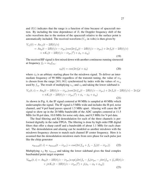
and R(t) indicates that the range is a function of time because of spacecraft motion.<br />
By including the time dependence of R, the Doppler frequency shift of the<br />
echo waveform due to the motion of the spacecraft relative to the surface point is<br />
automatically included. The received waveform (V rf in volts) is then given by<br />
V rf (t) = As rf (t − 2R(t)/c)<br />
= Au p (t − 2R(t)/c − iτ pri )cos(2πf cg (t − 2R(t)/c − iτ pri ) + 2πf u (t − 2R(t)/c)<br />
+ πK 1 (t − 2R(t)/c − iτ pri ) 2 ) + φ u + φ cg )<br />
(19)<br />
The received RF signal is first mixed down with another continuous running sinousoid<br />
at frequency f d = m d f ctu .<br />
s d (t) = cos(2πf d t + φ d ) (20)<br />
where φ d is an arbitary starting phase for the mixdown signal. To deliver an intermediate<br />
frequency of 90 MHz regardless of the transmit tuning, the value of m d<br />
is chosen from the range [903, 965] synchronized by index with the values of m cg<br />
used by f cg . The result of multiplying s rf and s d and taking the lower sideband is<br />
V if (t, i) = Au p (t − 2R(t)/c − iτ pri )cos(2πf cg (t − 2R(t)/c − iτ pri ) + 2πf u (t − 2R(t)/c) − 2πf d t<br />
+ πK 1 (t − 2R(t)/c − iτ pri ) 2 ) + φ u − φ d + φ cg )<br />
(21)<br />
As shown in Fig. 6, the IF signal centered at 90 MHz is sampled at 40 MHz which<br />
undersamples the signal. The IF signal is 5 MHz wide and includes the H-pol, noise<br />
channel, and V-pol band passes spaced 1.5 MHz apart. Aliasing will cause the IF<br />
signal to show up in the 20 MHz bandwidth of the ADC samples centered at 11.5<br />
MHz for H-pol data, 10.0 MHz for noise only data, and 8.5 MHz for V-pol data.<br />
The final filtering and IQ demodulation for each of the three channels is performed<br />
digitally in the radar FPGA. The filtering is done by high order FIR digital<br />
filters that offer a sharp cutoff and a bandwidth of about 1.1 MHz for each channel.<br />
The demodulation and aliasing can be modeled as another mixdown with the<br />
mixdown frequency chosen to match each channel IF center frequency. Here it is<br />
assumed that the demodulation mixdown starts from zero phase for each pulse just<br />
like the chirp generator<br />
s demod (t, i) = s demod (t − iτ pri ) = cos(2π(f cg + f u − f d )(t − iτ pri )) (22)<br />
Multiplying s if by s demod and taking the lower sideband gives the final complex<br />
basebanded point target response<br />
V bbpt (t, i) = Au p (t − 2R(t)/c − iτ pri )exp(j2π(f u − f d )iτ pri − j4π(f cg + f u )R(t)/c<br />
+ jπK 1 (t − 2R(t)/c − iτ pri ) 2 ) + j(φ u − φ d + φ cg ))<br />
(23)