QView QD1200 Operation Manual (HiRes 879 KB) - Qomo
QView QD1200 Operation Manual (HiRes 879 KB) - Qomo
QView QD1200 Operation Manual (HiRes 879 KB) - Qomo

Create successful ePaper yourself
Turn your PDF publications into a flip-book with our unique Google optimized e-Paper software.
PRECAUTIONS<br />
Please follow these precautions:<br />
To prevent fire or shock hazard, do not expose the unit to rain or moisture.<br />
To prevent electrical shock, do not open the cabinet. Refer to qualified<br />
personnel for service only.<br />
Do not use the unit continuously for more than 24 hours with camera auto<br />
focus on. It may cause damage to the camera lens.<br />
Be careful not to spill water or other liquids onto the unit, or allow combustible<br />
or metallic objects to get inside the cabinet.<br />
Unplug the visualizer from the wall outlet when it is not being used for<br />
a long period of time.<br />
Clean the cabinet with a soft cloth lightly moistened with a mild detergent<br />
solution.<br />
Clean the lens carefully with an air spray or soft dry cloth to avoid scratching<br />
it.<br />
When the lamps flash or become dark, they should be replaced with new<br />
ones.<br />
Avoid switching arm lights and back light frequently.<br />
CONTACTS:<br />
QOMO Hitevision, LLC<br />
Toll Free: 1-866-990QOMO<br />
E-Mail: info@qomo.com<br />
Web: www.qomo.com<br />
1
CONTENTS:<br />
PARTS IDENTIFICATION ............................................................................... 3<br />
CONTROL PANEL .......................................................................................... 3<br />
BUTTON INSTRUCTION................................................................................ 4<br />
REMOTE CONTROL ...................................................................................... 5<br />
CONNECTIONS ............................................................................................. 6<br />
BASIC PREPARATIONS................................................................................. 6<br />
OUTPUT MODE AND VERTICAL FREQUENCY (60Hz).............................. 10<br />
PAL/NTSC VIDEO OUTPUTS ...................................................................... 10<br />
INSTALLING QOMO VISUALIZER SOFTWARE ...........................................11<br />
WORKING ON THE STAGE ......................................................................... 13<br />
WORKING OUTSIDE THE STAGE............................................................... 13<br />
LIGHT ........................................................................................................... 14<br />
ADJUSTING IMAGE SIZE ............................................................................ 14<br />
WORKING WITH NEGATIVES ..................................................................... 14<br />
FOCUSING ................................................................................................... 15<br />
FREEZING IMAGE ....................................................................................... 15<br />
BRIGHTNESS ADJUSTMENT...................................................................... 15<br />
WHITE BALANCE ADJUSTMENT................................................................ 15<br />
AUTO ADJUSTMENT ................................................................................... 15<br />
TEXT/IMAGE MODE..................................................................................... 15<br />
COLOR AND B&W MODE SWITCH............................................................. 16<br />
SWITCHABLE VIDEO INPUTS .................................................................... 16<br />
SWITCHABLE RGB INPUTS........................................................................ 16<br />
PROJECTOR ON/STANDBY........................................................................ 16<br />
PROJECTOR INPUTS SELECTION............................................................. 16<br />
IMAGE ROTATION ....................................................................................... 16<br />
IMAGE REVERSION .................................................................................... 17<br />
INFRARED REMOTE CONTROL................................................................. 17<br />
PRESET FUNCTION .................................................................................... 17<br />
3 X 3 MULTIPLE SCREEN DISPLAY............................................................ 17<br />
USB PORT.................................................................................................... 17<br />
2
USB IMAGE CAPTURE ................................................................................ 18<br />
CONTROLLING THE VISUALIZER FROM THE COMPUTER ..................... 19<br />
CONTROLLING PROJECTOR BY VISUALIZER.......................................... 19<br />
FOLDING THE UNIT..................................................................................... 23<br />
SPECIFICATIONS ........................................................................................ 24<br />
TECHNICAL SUPPORT................................................................................ 26<br />
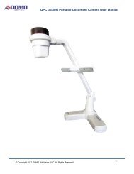
PARTS IDENTIFICATION<br />
Camera<br />
Camera stand<br />
Arm lights<br />
Connectors<br />
Button instruction<br />
Remote control slot<br />
Back light<br />
Stage<br />
Connectors<br />
<strong>Operation</strong> panel<br />
CONTROL PANEL<br />
Rot (Rotate the image)<br />
Frz (Freeze the image)<br />
Neg (Display film negatives)<br />
Text (Switch between image/text mode)<br />
3
Save (Save captured images)<br />
Far/Near (Focus far or near)<br />
Mem (Multiple Screen Display)<br />
Ppw (Control the projector On/Standby)<br />
Pin (Projector input signal selection)<br />
/ (Move the image up/down)<br />
POWER (Control the visualizer On/Off)<br />
CCD/PC1/PC2 (CCD/RGB input signal selection)<br />
S-VIDEO/ VIDEO (S-VIDEO/ VIDEO input signal selection)<br />
LAMP (Control the arm lights and back light)<br />
AUTO (To auto adjust brightness, auto white balance and auto focus)<br />
+ T/W (Increase and decrease magnification)<br />
BUTTON INSTRUCTION<br />
4
REMOTE CONTROL<br />
POWER (Control the visualizer power On/Off)<br />
ROTATE (Rotate the image)<br />
FREEZE (Freeze the image)<br />
LAMP (Control the arm lights and back light)<br />
SAVE (Save captured images)<br />
NEG (Display film negatives)<br />
MIRROR (V-reverse the image)<br />
XGA (Switch between SVGA mode and XGA mode)<br />
RECALL (Multiple screen display)<br />
TEXT (Switch between image/text mode)<br />
B&W (Switch between Color mode and Black & White mode)<br />
SPLIT (Image split function)<br />
PROJECTOR POWER (Control the projector On/Standby)<br />
PROJECTOR INPUT (Projector input signal selection)<br />
EXIT (Exit selected function)<br />
TELE/ WIDE (Increase and decrease magnification)<br />
FAR/NEAR (Focus near or far)<br />
5
AUTO (To auto adjust brightness, auto white balance and auto focus)<br />
CCD/PC1/PC2 (CCD/RGB input signal selection)<br />
S-VIDEO/ VIDEO (S-VIDEO/ VIDEO input signal selection)<br />
VOLUME+/- (Increase or decrease the volume)<br />
RED+/- (Increase or decrease the red hue)<br />
BLUE+/- (Increase or decrease the blue hue)<br />
BRIGHT+/- (Increase or decrease the brightness)<br />
SCROLL / (Move the image up/down)<br />
CONNECTIONS<br />
7<br />
8<br />
OUT<br />
OUT<br />
IN<br />
IN<br />
AUDIO VIDEO<br />
S-VIDEO<br />
AUDIO VIDEO<br />
AUDIO<br />
S-VIDEO AUDIO IN<br />
PROJECTOR OUT -COMPUTER- IN OUT-12V- IN<br />
Side Panel<br />
18<br />
PROJECTOR MIC<br />
USB<br />
RGB IN AUDIO IN RS232<br />
#1 AUDIO OUT #2 VIDEO OUT #3 S-VIDEO OUT<br />
#4 VIDEO AUDIO IN #5 VIDEO IN #6 S-VIDEO AUDIO IN<br />
#7 S-VIDEO IN #8 PC AUDIO IN<br />
#9 PROJECTOR Connector #10 COMPUTER OUT<br />
#11 COMPUTER IN #12 POWER OUT/IN<br />
#13 PROJECTOR RS232 Connector #14 MIC IN<br />
#15 USB Connector #16 RGB IN<br />
#17 RGB AUDIO IN #18 COMPUTER RS-232 Connector<br />
BASIC PREPARATIONS<br />
6
1. Use one hand holds the base of the visualizer, use the other hand<br />
carefully lift up the camera stand of the unit.<br />
2. Open the arm lights and rotate the camera head until they are in proper<br />
positions.<br />
Arm lights<br />
3. Making connections:<br />
Before making any connection, turn off all the power, including power of<br />
the visualizer and the equipment to be connected.<br />
Step 1: Connect power source.<br />
First connect the power cord to the 12V IN connector.<br />
Step 2: Connect to the projector.<br />
7
Rear Panel<br />
OUT<br />
OUT<br />
IN<br />
IN<br />
AUDIO VIDEO<br />
S-VIDEO<br />
AUDIO VIDEO<br />
AUDIO S-VIDEO AUDIO IN PROJECTOR OUT -COMPUTER- IN OUT-12V- IN<br />
RGB Input<br />
RS232 Cable<br />
Screen<br />
Projector<br />
Side Panel<br />
PROJECTOR MIC USB RGB IN AUDIO IN RS232<br />
Connect visualizer’s PROJECTOR port to the RGB IN port of the projector<br />
port with the RGB cable provided together the visualizer.<br />
If you need control a projector with the visualizer, please use the projector<br />
RS232 cable (6-pin to 9-pin) to make the connection between the projector<br />
and the visualizer. Some projector models may require a converter cable in<br />
addition to this standard RS232 cable to connect to the projector control<br />
port, for the pin locations and shape of some projectors’ control port<br />
connector may be different from the connector of a standard RS232 cable.<br />
After the visualizer is connected to the projector, you can control projector’s<br />
power on, standby and input selection with the visualizer. (For projectors<br />
other than Hitachi, the Code Writing program that comes with the visualizer<br />
is required for this function.)<br />
Step 3: Connect to a desktop computer.<br />
Rear Panel<br />
OUT OUT<br />
IN<br />
AUDIO VIDEO S-VIDEO AUDIO VIDEO<br />
IN<br />
AUDIO S-VIDEO AUDIO IN PROJECTOR OUT -COMPUTER- IN OUT-12V- IN<br />
To the<br />
Monitor<br />
RGB Output<br />
USB Connector<br />
RS232<br />
Cable<br />
Computer<br />
PROJECTOR MIC<br />
USB RGB IN AUDIO IN<br />
RS232<br />
8<br />
Side Panel
Note: You can connect a laptop computer to the RGB IN port of side panel<br />
with a RGB cable.<br />
Step 4: Connect to the first video equipment with S-Video input.<br />
S-Video Cable<br />
S-Video out<br />
Audio out<br />
Video equipment<br />
Rear Panel<br />
OUT<br />
OUT<br />
IN<br />
IN<br />
AUDIO<br />
VIDEO S-VIDEO AUDIO VIDEO<br />
AUDIO<br />
S-VIDEO<br />
AUDIO IN<br />
PROJECTOR<br />
OUT -COMPUTER- IN<br />
OUT-12V- IN<br />
Projector<br />
(or amplifier/speaker equipment)<br />
Audio input<br />
Output of the S-Video signal from the visualizer to the projector is already<br />
done in the step 2, where the RGB cable comes out from the visualizer and<br />
goes to the projector. After the connections as steps 2, 3, 4 are made, input<br />
signals from the computer、visualizer CCD and S-Video are going to the<br />
RGB1 input on the projector and will be displayed on the projector screen<br />
as RGB1. These signals can be seen in turn when pressing<br />
“CCD/PC1/PC2” and “S-VIDEO/VIDEO” on the control panel of the<br />
visualizer.<br />
Step 5: Connect to the second video equipment with video input.<br />
Video Cable<br />
Video out<br />
Audio out<br />
Video equipment<br />
Rear Panel<br />
OUT<br />
OUT<br />
IN<br />
IN<br />
AUDIO VIDEO S-VIDEO AUDIO VIDEO<br />
AUDIO<br />
S-VIDEO<br />
AUDIO IN PROJECTOR OUT -COMPUTER- IN OUT-12V- IN<br />
Projector Color monitor<br />
Video in<br />
9
Step 6: Connections for external control from the computer.<br />
Side Panel<br />
PROJECTOR MIC USB RGB IN AUDIO IN RS232<br />
USB cable<br />
RS-232 cable<br />
USB connector<br />
of the computer<br />
RS 232 connector<br />
of the computer<br />
Use the computer RS232 cable (9-pin to 9-pin) to make the<br />
connections shown below to control the visualizer from an external<br />
computer.<br />
USB connection enables capturing still images / video streams from<br />
the visualizer to the computer. Special software is required for this<br />
operation.<br />
4. Turn on the power by pressing the “POWER” button.<br />
OUTPUT MODE AND VERTICAL FREQUENCY (60Hz)<br />
The RGB output can output a signal in the SVGA /XGA format.<br />
In order to achieve the best picture quality you must set the outputs of the<br />
Visualizer to match the native resolution of your display unit.<br />
PAL/NTSC VIDEO OUTPUTS<br />
The S-Video and composite video outputs are set to NTSC (PAL) during<br />
manufacturing.<br />
10
INSTALLING QOMO VISUALIZER SOFTWARE<br />
This function is to snap and display images with the USB interface, which<br />
includes displaying static and dynamic pictures, snapping dynamic images<br />
and playback the dynamic images with the media player in Windows XP.<br />
A. Connect the computer and visualizer with the USB cable. Insert the<br />
software CD that comes with your purchased visualizer into the<br />
CD-ROM drive. Turn on the visualizer. The setup will run automatically<br />
on your system, and then the QOMO Software Setup window will<br />
appear as below.<br />
B. Click , you will see the following setup window:<br />
C. Click and select , you will see the<br />
following setup window:<br />
11
D. Click , then copy files<br />
E. Click to finish the setup.<br />
F. Shut down your computer when prompted, so the changes will take<br />
effect.<br />
* Please pay attention to the following:<br />
1. Computer hardware requirement: CPU: 2.4GHz, RAM: 256M or above,<br />
Graphic card 64M, USB 2.0 port, Hard disk 40G or more, Monitor<br />
12
display resolution higher than XGA (1024*768).<br />
2. Operating system: Windows XP SP2 (Service Pack 2).<br />
3. Must use the high-speed USB cable provided together with the<br />
visualizer.<br />
4. When connect the visualizer to a desktop computer with the high-speed<br />
USB cable provided together with visualizer, we recommend using the<br />
USB port on the rear of the mainframe as the USB port on the front of<br />
the computer might have interference.<br />
5. You need to install the USB driver again when you change a<br />
computer’s USB port. If this port has installed USB2.0 driver, then no<br />
need to install USB driver again.<br />
WORKING ON THE STAGE<br />
1. Place your material on the working surface.<br />
2. Select the enlargement required with the “ + T” and “W ” keys.<br />
3. Adjust the focus with the “Near” and “Far” keys or “AUTO” key.<br />
WORKING OUTSIDE THE STAGE<br />
For showing 3-dimensional objects with the visualizer, just place them on<br />
the working surface and adjust the “ + T” or “W ” and “AUTO” keys. If the<br />
object is too big for the stage or you want to show it from the side, just<br />
place it behind or in front of the unit and tilt the camera by hand (please<br />
take off the close-up lens first).<br />
Rotate 330 degrees<br />
vertically<br />
13
LIGHT<br />
The arm lights are on when the power is on. Each time you press the<br />
“LAMP” buttons, the lighting changes as below.<br />
The arm lights turn on<br />
The back light turns on<br />
All the lights turn off<br />
ADJUSTING IMAGE SIZE<br />
In order to reduce or enlarge the image size displayed on the screen, press<br />
the “ + T” or “W ” button.<br />
WORKING WITH NEGATIVES<br />
The visualizer is automatically set to display normal materials on the<br />
screen when the power is on. To display negatives, turn on the backlight by<br />
pressing the “LAMP” key, and then press the “Neg” button to display the<br />
film negatives. Press the “Neg” button again to display normal materials in<br />
the color mode.<br />
14
FOCUSING<br />
When the Visualizer is turned on the focus automatically adjusts to the<br />
stage, it is not necessary to readjust the focus if you are only working with<br />
flat materials (text, photos, etc.). Only 3D objects require a focus<br />
adjustment.<br />
Press the “AUTO” button to auto focus.<br />
Press the “FAR” or “NEAR” button once to focus manually.<br />
FREEZING IMAGE<br />
Press the “Frz” button to freeze the image. When the output signal is RGB,<br />
in order to show a still image on the screen, press the “Frz” button. The<br />
frozen image can’t be adjusted (Zoom in/out, color adjustment, etc.).<br />
BRIGHTNESS ADJUSTMENT<br />
If the image effect is not satisfactory, you can adjust the brightness to get a<br />
better image effect. Use the “BRIGHT +” or “BRIGHT -” button to adjust the<br />
brightness. To increase the brightness, press the “BRIGHT +” button. To<br />
decrease it, press the “BRIGHT -” button. To go back to the initial<br />
brightness press the “AUTO” button.<br />
WHITE BALANCE ADJUSTMENT<br />
Each time the lighting condition changes, the user should adjust the white<br />
balance of the CCD.<br />
Press the “AUTO” button to adjust the white balance automatically.<br />
AUTO ADJUSTMENT<br />
One of the <strong>QD1200</strong>’s special functions is auto adjustment. Press the<br />
“AUTO” button to auto adjust the brightness, the white balance and the<br />
focus.<br />
TEXT/IMAGE MODE<br />
Press the “Text” button to switch between image/text modes. To display a<br />
15
text file, switch to the text mode to get a clearer text effect.<br />
COLOR AND B&W MODE SWITCH<br />
Press “B&W” once to enter the Black & White mode; press again to return<br />
to the Color mode. (On the remote control)<br />
SWITCHABLE VIDEO INPUTS<br />
Press the “S-VIDEO/VIDEO” button to switch among S-Video and Video<br />
signals.<br />
SWITCHABLE RGB INPUTS<br />
Use the “CCD/PC1/PC2” button to switch between CCD and different RGB<br />
signals. Each time the “CCD/PC1/PC2” button is pressed, it provides<br />
seamless transitions among different sources such as Camera (CCD)、<br />
COMPUTER(IN)、and RGB (IN).<br />
Notes: RGB OUT always outputs RGB IN signals.<br />
PROJECTOR ON/STANDBY<br />
Press the “POWER” button to turn on the <strong>QD1200</strong>’s power and press the<br />
“Ppw” button to turn the projector power on. To turn the projector standby<br />
after use, press the “Ppw” button more than 2 seconds, and then the<br />
projector enters to the standby mode. (On the remote control, press the<br />
“PROJECTOR POWER” button)<br />
PROJECTOR INPUTS SELECTION<br />
When the projector is connected to several input sources, use the “Pin”<br />
button to switch signal inputs of the projector. (On the remote control, press<br />
the “PROJECTOR INPUT” button)<br />
IMAGE ROTATION<br />
In order to rotate the image, press the “Rot” button once, the displayed<br />
image will be rotated ±90 degrees clockwise. Press the “Rot” button again,<br />
the rotated image will be restored to the initial position.<br />
16
IMAGE REVERSION<br />
Press the “MIRROR” button once to V-reverse the image and the<br />
vertically mirrored image will be displayed. Press the “MIRROR” button<br />
again to exit.<br />
INFRARED REMOTE CONTROL<br />
The <strong>QD1200</strong>’s remote control can control the camera from different angels.<br />
Please note that an infrared remote control can only be used up to a<br />
certain distance to the unit. Objects situated between the visualizer and the<br />
infrared remote control and a weak battery may interfere with the reception.<br />
On the left side of the visualizer stage, there is a built-in remote control<br />
storage compartment where you can store the remote control when you not<br />
use it.<br />
PRESET FUNCTION<br />
Use the “SET” button to preset 8 steps of the Zoom/Focus position, when<br />
the button is pressed, it moves step by step. Press “RUN” button to the run<br />
preset. (On the remote control)<br />
3 X 3 MULTIPLE SCREEN DISPLAY<br />
Press “Mem” button, the stored images can be displayed in a 3 x 3 matrix.<br />
Press “Mem” once, the stored images can be displayed in a 3 x 3 matrix.<br />
Press the numeric buttons to display the corresponding images. Under this<br />
operation, the “Frz”, “Neg”, “Txt”, “Far”, “Near”, “Ppw”, “Pin”, “↓” and “↑”<br />
buttons do not function. Press “Mem” again to exit the 3 x 3 image display<br />
mode.<br />
On the remote control, the “RECALL” and numeric buttons are the image<br />
recall and selection keys.<br />
USB PORT<br />
The USB port can be used to store still images from the visualizer in a<br />
computer. No additional computer hardware is required. In this way, the<br />
17
visualizer can be used as a 3-D scanner for your computer.<br />
Connect the Visualizer to your computer with the supplied USB cable.<br />
The QOMO Visualizer Software is available on the supplied CD-ROM.<br />
USB IMAGE CAPTURE<br />
You can capture and control images on the visualizer from a computer<br />
connected with a USB connector.<br />
A. Connect the computer and the visualizer with the USB cable.<br />
B. Double click X:\ USB Capture\ (you can open this file from the<br />
CD and double click this software, or copy this file into any directory on<br />
your computer hard drive and double click it), you will see the following<br />
computer control window:<br />
The control keys’ operation is the same to the operating instruction of<br />
the “Controlling the Visualizer From a Computer” section.<br />
C. Menu operation instructions.<br />
Close / Open the computer control window.<br />
Display the image in full screen.<br />
Click<br />
to get a present picture frame from CCD.<br />
Download the 9 images stored in the visualizer into your desired<br />
18
folder on your computer.<br />
Display the current visualizer images continuously (the fastest<br />
frame rate is 10 frames per second)<br />
Stop image continuous display<br />
Choose the image displaying size.<br />
Open an image.<br />
Save the captured image to computer.<br />
CONTROLLING THE VISUALIZER FROM THE COMPUTER<br />
You can control the visualizer from a computer connected with a RS232<br />
connector.<br />
A. Connect the computer and the visualizer with the RS232 cable.<br />
B. Double click X:\ 232 Control\Control Panel (you can open this file from<br />
the CD and double click it, or copy this file to any directory on your<br />
computer’s hard drive and double click to launch it).<br />
CONTROLLING PROJECTOR BY VISUALIZER<br />
The code writing software is used to inputting projector’s control code, then<br />
can control various projector with the visualizer.<br />
1. Connect the visualizer to the projector with the RGB、VIDEO、S-VIDEO<br />
cables.<br />
2. Connect the RS232 cable to the computer’s connector. The visualizer’s<br />
RS232 port is located on its right side.<br />
3. After completion of the connection, turn on the visualizer,click [start] -><br />
[All Programs] -> Visualizer -><br />
and the following<br />
dialog box appears as below:<br />
19
When the indicator of “Current RS-232 Connection Status” is green, that<br />
means the connection between the visualizer and the computer’s RS232<br />
connector is good. If the indicator is red, please check if the RS232 cable is<br />
connected correctly. When all the cables are connected correctly, please<br />
click “Projector” to select your projector model under the drop-down list,<br />
then click “Send”. If you can not find your particular projector model in the<br />
“Projector”, please do the following:<br />
1).Select “Baud rate” and “parity” and input the projector control code.<br />
(The baud rate, parity and control code is supplied by projector’s<br />
manufacturer, please refer to the projector’ manual)<br />
The input format of projector’s control code is as follows:<br />
a. If the data is in the numerical value format, please input data directly,<br />
block them off with comma, do not distinguish lowercase and uppercase.<br />
For example: the “POWER ON” code in Hitachi projector manual is :<br />
20
BE EF 03 06 00 BA D2 01 00 00 60 01 00<br />
In the POWRE ON box,Input : be, ef, 03, 06, 00, ba, d2, 01, 00, 00, 60, 01,<br />
00. Then use the same input rule to input other code.<br />
b. If the data is in the character string format, input ‘character string’.<br />
For example: the “POWER ON” code in the SHARP C40/50 projector<br />
manual is :<br />
P O W E - - - 1<br />
( “-“ is space, is enter.)<br />
In the POWER ON box, input ’POWR 1’, 0d, 0a<br />
(Remarks: There are 3 spaces after POWER, 0d, 0a is enter.)<br />
Input other codes in the same way.<br />
c. If the data is in the numerical value and character format, then<br />
synthesize the above-mentioned formats.<br />
3).Once done, click “Add” to add your projector model, then Click “Send”.<br />
Afterward, click “Ok”. Now, you can use the visualizer to control your<br />
projector.<br />
4. Connect the visualizer’s projector control port to the RS232 port with a<br />
RS232 cable(Please disconnect the computer from the RS232 port first).<br />
Then use buttons on the operation panel to control the projector.<br />
The visualizer provides a 6-pin to 9-pin RS232 cable. If this cable does not<br />
match to your projector’s RS232 port, an additional RS232 cable is needed.<br />
This additional RS232 cable can be made based on the pin location of the<br />
projector’s RS232 control port. The pin locations of the visualizer are: the<br />
pin 1 is RXD (Received Data); the pin 5 is TXD (Transmitted Data); the pin<br />
4 is GND (Ground). Other pins are not defined. The pin location information<br />
of the projector is provided by the projector’s manufacturer. The projector’s<br />
RS232 control port normally has RXD pin, TXD pin and GND pin, the name<br />
may be different. The parallelism of each data pin<br />
is shown as follows: 6 5<br />
Visualizer’s RXD pin------------Projector’s TXD pin 4 3<br />
2 1<br />
21
Visualizer’s TXD pin------------Projector’s RXD pin<br />
Visualizer’s GND pin------------Projector’s GND pin<br />
5. If you can not use buttons on the operation panel to control the projector,<br />
please use Code-Writing software’s projector control code testing function<br />
to check if the control code is correct.<br />
Click “Projector” button, the following dialog box appears as below:<br />
Connect the visualizer to a computer with a RS232 cable (Please<br />
disconnect the projector from the RS232 port first) and select the Baud<br />
Rate and Parity based on the projector’s Baud Rate, then click the “TEST”<br />
button to pop up the Projector Code Test dialog box, input the Baud Rate<br />
and Parity based on the projector’s Baud rate, then click “Open”.<br />
Click the projector control buttons on the visualizer’s operating panel to<br />
check if the control code that the program received is the same as the<br />
sending code. If the receiving code is same to the sending code, the input<br />
codes are correct. If the visualizer can not control the projector, please do<br />
the following.<br />
22
1. Check to see if the source control codes of projector are correct.<br />
2. Check to make sure the connection between the visualizer and the<br />
projector is correct.<br />
FOLDING THE UNIT<br />
1. Fold the right arm light down first onto the base, then the left arm down.<br />
Rotate the camera head clockwise until the camera head is parallel to the<br />
camera stand.<br />
2. Carefully Fold the camera stand down to the front panel.<br />
23
Cautions:<br />
a. Don’t lay the unit down flat.<br />
b. Don’t try to stand it on its rear or sides.<br />
c. Don’t try to pick up this unit by pulling the camera stand.<br />
NOT THIS WAY<br />
SPECIFICATIONS<br />
Color system<br />
NTSC or PAL system<br />
Pickup device<br />
1/3″CCD<br />
Resolution XGA (1024 x 768)<br />
Total Pixels 850,000<br />
Lens<br />
12 x optical zoom, 8 x electrical zoom<br />
F=1.8~2.7 mm / f = 5.4 ~ 64.8 mm<br />
Zoom<br />
Powered<br />
Camera Rotation Vertically 330°<br />
Focus/Iris<br />
Auto/manual selectable<br />
White balance<br />
Auto<br />
Negative/positive conversion Yes<br />
Black/white and color selection Yes<br />
24
Image Freeze<br />
Image Save & Recall<br />
Lights<br />
Input connectors<br />
Output connectors<br />
Yes<br />
9 frames save, 3 x 3 multiple screen<br />
display<br />
Arm light: 1.5W LED lamps x 2<br />
Back light: 4W LED lamps<br />
C Video IN (RCA) (1)<br />
S Video IN (4-pin DIN) (1)<br />
Audio IN (Mini Jack) (2)<br />
MIC IN (phone jack)(1)<br />
PC Audio (2)<br />
RGB DB15FLC (2)<br />
RGB DB15FLC (2)<br />
C Video OUT (RCA) (1)<br />
S Video OUT (4-pin DIN) (1)<br />
Audio OUT (Mini Jack) (1)<br />
Operating system Windows XP SP2 (Service pack 2)<br />
Hardware Requirement<br />
USB connector<br />
RS-232 connector<br />
USB port USB 2.0<br />
Power requirements<br />
Dimension (W x D x H)<br />
Weight<br />
Accessories<br />
CPU higher than P2.4GHz<br />
Memory higher than 256 MB<br />
15~20 frames/sec<br />
D-Sub, 9-pin, male / 6-pin PS/2<br />
12V/4A external AC adapter<br />
Folded: 20.1″ x 16.1″ x 4.7″<br />
Setup: 20.1″ x 20.9″ x 22.4″<br />
Packing: 25.6″ x 21.2″ x 9.1″<br />
N.W: 5.5Kg (12.1lbs)<br />
G.W: 9.5Kg (20.9 lbs)<br />
AC power cord<br />
RGB cable<br />
Audio/Video cable<br />
S-Video cable<br />
Computer RS232 cable (9-pin to 9-pin)<br />
25
Projector RS232 cable (6-pin to 9-pin)<br />
USB cable<br />
Audio convert cable<br />
AC adapter<br />
User’s manual<br />
Quick Start-up guide<br />
Software CD<br />
Infrared remote control<br />
Warranty card<br />
* Design and specifications are subject to change without prior notice.<br />
TECHNICAL SUPPORT<br />
How to Reach QOMO:<br />
By Phone<br />
Call us at 1-866-990QOMO. Our expert personnel provide technical<br />
assistance from 9:00AM through 5:00PM Eastern Standard Time,<br />
Monday through Friday. Please gather the following information before<br />
calling:<br />
- Product model name(s) and numbers<br />
- Product serial number(s)<br />
- Detailed and specific questions<br />
Online<br />
Technical support is also available online at QOMO’s web site at<br />
www.qomo.com. You can enter your questions and concerns through<br />
our online form. Or you can email us at info@qomo.com.<br />
Copyrights © 2004 QOMO Hitevision, LLC. All Rights Reserved.<br />
26