FMK4023-FMK4028 (2006) - World Marketing of America, Inc.
FMK4023-FMK4028 (2006) - World Marketing of America, Inc.
FMK4023-FMK4028 (2006) - World Marketing of America, Inc.

Create successful ePaper yourself
Turn your PDF publications into a flip-book with our unique Google optimized e-Paper software.
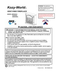
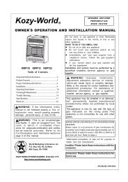
Kozy-<strong>World</strong> R<br />
FULL SIZE VENT-FREE<br />
FIREPLACE<br />
OWNER’S OPERATION AND INSTALLATION MANUAL<br />
<strong>FMK4023</strong><br />
FMK4024<br />
FMK4025<br />
FMK4026<br />
Table <strong>of</strong> Contents<br />
Safety Information Warnings......................................2<br />
Product Identification...................................................3<br />
Air for Combustion and Ventilation...........................4<br />
Installation.....................................................................6<br />
Operating heater.........................................................10<br />
Cleaning&Maintenance.............................................10<br />
Trouble Shooting.........................................................11<br />
Specifications..............................................................13<br />
Replacement Parts.....................................................14<br />
Parts List.......................................................................15<br />
Installing the Heater....................................................19<br />
WARNING: If the information in this<br />
manual is not followed exactly,a fire or<br />
explosion may result causing property<br />
damage,personalinjury, or loss <strong>of</strong> life.<br />
WARNING: This is an unvented gas-fired<br />
fireplace.It uses air (oxygen) from the room<br />
in which it is installed. Provisions for<br />
adequate combustion and ventilation air must<br />
be provided. Refer to Air For Combustion<br />
and Ventilation section on page 4 <strong>of</strong> this<br />
manual.<br />
Do not store or use gasoline or other flammable<br />
vapors and liquids in the vicinity <strong>of</strong> this or any<br />
other appliance.<br />
WHAT TO DO IF YOU SMELL GAS<br />
• Do not try to light any appliance.<br />
• Do not touch any electrical switch; do<br />
not use any phone in your building.<br />
• Immediately call your gas supplier from<br />
a neighbor’s phone. Follow the gas supplier’s<br />
instructions.<br />
• If you cannot reach your gas supplier,<br />
call the fire department. Installation and ser<br />
vice must be performed by a qualified<br />
installer,service agency,or local gas supplier.<br />
WARNING: Improper installation,<br />
adjustment, alteration, service or maintenance<br />
can cause injury or property damage.<br />
Refer to this manual for correct installation<br />
and operational procedures. For assistance<br />
or additional information, consult a qualified<br />
installer, service agency, or local gas supplier.<br />
This appliance may be installed in an aftermarket*,<br />
permanently located, manufactured<br />
(mobile) home, where not prohibited by<br />
local codes.<br />
This appliance is only for use with the type <strong>of</strong><br />
gas indicated on the rating plate. This<br />
appliance is not convertible for use with other<br />
gases.<br />
WATER VAPOR: A BY-PRODUCT OF NOVENTED ROOM<br />
HEATERS<br />
Water vapor is a by-product <strong>of</strong> gas combustion.An unvented<br />
room heater produces approxinately one(1) ounce (30ml)<br />
<strong>of</strong> water for every 1,000 BTU’s(3KW’s) <strong>of</strong> gas input per<br />
hour. Refer to page 3.<br />
Consumer: Please retain these instructions for future<br />
use.<br />
<strong>World</strong>-<strong>Marketing</strong> <strong>of</strong> <strong>America</strong>n,<strong>Inc</strong>.<br />
P.O.Box 192,Rt.22 West<br />
MillCreek,PA 17060<br />
Installer: Please leave these instructions with the<br />
consumer.<br />
KOZY-WORLD PHONE NUMBER:(814)643-1775<br />
http://www.worldmkting.com<br />
*Aftermarket: Completion <strong>of</strong> sale, not for purpose <strong>of</strong> resale,<br />
from the manufacturer.
SAFETY INFORMATION WARNINGS<br />
IMPORTANT: Read this<br />
owner’s manual carefully and<br />
completely before trying to<br />
assemble, operate, or service<br />
this fireplace. Improper use <strong>of</strong><br />
this fireplace can cause serious<br />
injury or death from burns,<br />
fire, explosion, electrical<br />
shock, and carbon monoxide<br />
poisoning.<br />
DANGER: Carbon monoxide<br />
poisoning may lead to death!<br />
Carbon Monoxide Poisoning:<br />
Early signs <strong>of</strong> carbon monoxide<br />
poisoning resemble the flu with<br />
headaches, dizziness, or nausea.<br />
If you have these signs, the fireplace<br />
may not be working properly. Get<br />
fresh air at once! Have the fireplace<br />
serviced. Some people are more<br />
affected by carbon monoxide than<br />
others. These include pregnant<br />
women, people with heart or lung<br />
disease, anemia, those under the<br />
influence <strong>of</strong> alcohol, and those<br />
at high altitudes.<br />
Propane/LP Gas: Propane/LP gas<br />
is odorless. An odor-making agent<br />
is added to Propane/LP gas. The<br />
odor helps you detect a Propane/LP<br />
gas leak . However, the odor added<br />
to Propane/LP gas can fade. Propane/LP<br />
gas may be present even<br />
though no odor exists.<br />
Make certain you read and understand<br />
all warnings. Keep this manual<br />
for reference. It is your guide to safe<br />
and proper operation <strong>of</strong> this fireplace.<br />
WARNING: Any change to<br />
this fireplace or its controls can<br />
be dangerous.<br />
WARNING: Do not allow fans to<br />
blow directly into the fireplace. Avoid<br />
any drafts that alter burner flame<br />
patterns. Ceiling fans can create drafts<br />
that alter burner flame patterns. Altered<br />
burner patterns can cause sooting.<br />
WARNING: Do not use accessories<br />
not approved for use with<br />
this fireplace.<br />
Due to high temperatures, the<br />
appliance should be located out <strong>of</strong><br />
traffic and away from furniture<br />
and draperies.<br />
Do not place clothing or other<br />
flammable material on or near the<br />
appliance. Never place any objects<br />
in the fireplace.<br />
Heater becomes very hot when<br />
running fireplace. Keep children and<br />
adults away from hot surfaces to<br />
avoid burns or clothing ignition.<br />
Fireplace will remain hot for a short<br />
time after shutdown. Allow surfaces<br />
to cool before touching.<br />
Carefully supervise young children<br />
when they are in the room with the<br />
fireplace.<br />
You must operate this fireplace with<br />
the fireplace screen in place. Make<br />
sure the fireplace screen is in place<br />
before running the fireplace.<br />
Keep the appliance area clear and<br />
free from combustible materials,<br />
gasoline, and other flammable<br />
vapors and liquids.<br />
1. This appliance is only for use<br />
with the type <strong>of</strong> gas indicated<br />
on the rating plate. This<br />
appliance is not convertible for<br />
use with other gases.<br />
2. Do not place propane/LP<br />
supply tank(s) indoors.<br />
3. If you smell gas<br />
• Shut <strong>of</strong>f gas supply.<br />
• Do not try to light any appliance.<br />
•Do not touch any electrical switch<br />
do not use any phone in your<br />
building.<br />
• Immediately call your gas supplier<br />
from a neighbor’s phone.<br />
Follow the gas supplier’s<br />
instructions.<br />
•If you cannot reach your gas<br />
supplier,call the fire department.<br />
4. This fireplace shall not be installed<br />
in a bedroom or bathroom.<br />
5. Do not use this fireplace as a<br />
wood-burning fireplace. Use only<br />
the logs provided with the fireplace.<br />
6. Do not add extra logs or ornaments<br />
such as pine cones, vermiculite, or<br />
rock wool.Using these added items<br />
can cause sooting. Do not add lava<br />
rock around base. Rock and debris<br />
could fall into the control area <strong>of</strong><br />
fireplace. After servicing, always<br />
replace screen before operating<br />
fireplace.<br />
7. You must operate this fireplace<br />
with the fireplace screen in place.<br />
Make sure the fireplace screen is<br />
in place before running the<br />
fireplace.<br />
8. This fireplace is designed to be<br />
smokeless. If logs ever appear to<br />
smoke, turn <strong>of</strong>f the fireplace and<br />
call a qualified service person.<br />
Note: During initial operation,<br />
slight smoking could occur due to<br />
log curing and fireplace burning<br />
manufacturing residues.<br />
9. To prevent the creation <strong>of</strong> soot,<br />
follow the instructions in Cleaning<br />
and Maintenance on page 10.<br />
10. Before using furniture polish, wax,<br />
carpet cleaner, or similar products,<br />
turn fireplace <strong>of</strong>f. If heated, the<br />
vapors from these products may<br />
create a white powder residue<br />
within burner box or on adjacent<br />
walls or furniture.<br />
11.This fireplace needs fresh air<br />
ventilation to run properly. This<br />
fireplace has an Oxygen Depletion<br />
Sensing (ODS) safety shut<strong>of</strong>f<br />
system. The ODS shuts down the<br />
fireplace if not enough fresh air is<br />
available. See Air for Combustion<br />
and Ventilation, pages 4 through 5.<br />
If fireplace keeps shutting <strong>of</strong>f, see<br />
Troubleshooting, pages 11 through<br />
12.<br />
12. Do not run fireplace<br />
•Where flammable liquids or<br />
vapors are used or stored.<br />
•Under dusty conditions.<br />
13. Do not use this fireplace to cook<br />
food or burn paper and other<br />
objects.<br />
14. Do not use fireplace if any part has<br />
been under water. lmmediately call<br />
a qualified service technician to<br />
inspect the room fireplace and to<br />
replace any part <strong>of</strong> the control<br />
system, and any gas control, which<br />
has been under water.<br />
2
SAFETY<br />
INFORMATION<br />
Continued<br />
15. Turn <strong>of</strong>f and unplug fireplace and<br />
let cool before servicing. Only a<br />
qualified service person should<br />
service and repair fireplace.<br />
16. Operating fireplace above<br />
elevtions <strong>of</strong> 4,500 feet could<br />
cause pilot outage.<br />
17. Do not operate fireplace if any log<br />
is broken. Do not operate fire<br />
place if a log is chipped(dimesized<br />
or larger).<br />
18. To prevent performance problems,<br />
do not use fuel tanks <strong>of</strong> less than<br />
100 lbs. capacity.<br />
LOCAL CODES<br />
lnstall and use fireplace with care.<br />
Follow all local codes. In the<br />
absence <strong>of</strong> local codes, use the<br />
latest edition <strong>of</strong> The National Fuel<br />
Gas Code. ANS Z223.1, also known<br />
as NFPA54*.<br />
*Available from:<br />
<strong>America</strong>n National Standards<br />
lnstitute, lnc.<br />
1430 Broadway<br />
New York. NY10018<br />
National Fire Protection<br />
Association, lnc.<br />
Batterymarch Park<br />
Quincy. MA 02269<br />
This fireplace is designed for<br />
vent-free operation. State and local<br />
codes in some areas prohibit the<br />
use <strong>of</strong> vent-free fireplace.<br />
UNPACKING<br />
1. Remove top inner pack.<br />
2. Tilt carton so that fireplace is upright.<br />
3. Remove protective side packaging.<br />
4. Slide fireplace out <strong>of</strong> carton bottom.<br />
5. Remove protective plastic wrap<br />
6. Take out the base from the package<br />
and install it as shown Figure (Page<br />
23).<br />
7. Remove screen by lifting and then<br />
pulling forward.<br />
8. Remove log set by cutting plastic<br />
ties.<br />
9. Carefully unwrap logs.<br />
10.Check for any shipping damage. If<br />
fireplace or any logs are damaged,<br />
promptly inform dealer where you<br />
bought the fireplace.<br />
PRODUCT FEATURES<br />
SAFETY PILOT<br />
This fireplace has a pilot with an<br />
Oxygen Depletion Sensing (ODS)<br />
safety shut<strong>of</strong>f system. The ODS/<br />
pilot is a required feature for ventfree<br />
fireplace. The ODS/pilot shuts<br />
<strong>of</strong>f the fireplace if there is not<br />
enough fresh air.<br />
PIEZO IGNITION SYSTEM<br />
This fireplace has a piezo ignitor.<br />
This system requires no matches,<br />
batteries, or other sources to light<br />
fireplace.<br />
PRODUCT IDENTIFICATION<br />
Figure1 - FULL SIZE VENT-FREE FIREPLACE<br />
WATER VAPOR: A BY-PRODUCT OF UNVENTED ROOM HEATERS<br />
Water vapor is a by-product <strong>of</strong> gas combustion. An unvented room heater produces approximately one(1) ounce<br />
(30ml) <strong>of</strong> water for every 1,000 BTU’s(3KW’s)<strong>of</strong> gas input per hour.<br />
Unvented room heaters are recommended as supplemental heater(a room). Rather than a primary heat source<br />
(an entire house). In most supplemental heat applications, the water vapor does not create a problem. In most<br />
applications,the water vapor enhances the low humidity atmosphere experienced during cold weather.The folling<br />
steps will help insure that water vapor does not become a problem.<br />
1.Be sure the heater is a sized properly for the application, including ample combustion air and circulation air.<br />
2.If high humidity is experienced,dehumidifier may be used to help lower the water vapor content <strong>of</strong> the air.<br />
3.Do not use an unvented room heater as the primary heat source.<br />
3
AIR FOR COMBUSTION AND VENTILATION<br />
WARNING: This fireplace<br />
shall not be installed in a confined<br />
space or unusually tight construction<br />
unless provisions are provided<br />
for adequate combustion and ventilation<br />
air. Read the following instructions<br />
to insure proper fresh air<br />
for this and other fuel-burning appliances<br />
in your home.<br />
PROVIDING ADEQUATE<br />
VENTILATION<br />
The following are excerpts from<br />
National Fuel Gas Code, NFPA 54/<br />
ANS Z223.1.Section 5.3, Air for<br />
Combustion and Ventilation.<br />
All spaces in homes fall into one<br />
<strong>of</strong> the three following ventilation<br />
classifications:<br />
1. Unusually Tight Construction<br />
2. Unconfined Space<br />
3. Confined Space<br />
The information on pages 4 through<br />
5 will help you classify your space<br />
and provide adequate ventilation.<br />
Confined and Unconfined Space<br />
The National Fuel Gas Code, ANS<br />
Z223.1 defines a confined space as<br />
a space whose volume is less<br />
than 50 cubic feet per 1,000 Btu per<br />
hour (4.8 m 3 per kw) <strong>of</strong> the aggregate<br />
input rating <strong>of</strong> all appliances<br />
installed in that space.An<br />
unconfining space is defined as a<br />
space whose volume is not less<br />
than 50 cubic feet per 1,000 Btu per<br />
hour (4.8 m 3 per kw) <strong>of</strong> the aggregate<br />
input rating <strong>of</strong> all appliances<br />
installed in that space. Rooms communicating<br />
directly with the space<br />
in which the appliances are<br />
installed*, through openings not<br />
furnished with doors, are considered<br />
a part <strong>of</strong> the unconfined<br />
space.<br />
This fireplace shall not be installed<br />
in a confined space or unusually<br />
tight construction unless provisions<br />
are provided for adequate combustion<br />
and ventilation air.<br />
* Adjoining rooms are communicating<br />
only if there are door-less<br />
passage ways or ventilation grills<br />
between them.<br />
AIR FOR COMBUSTION AND VENTILATION<br />
Unusually Tight Construction<br />
DETERMINING FRESH-AIR FLOW FOR HEATER LOCATION<br />
Determining if You Have a Confined or Unconfined Space<br />
Use this worksheet to determine if you have a confined or unconfined space.<br />
Space: <strong>Inc</strong>ludes the room in which you will install heater plus any adjoining rooms with doorless passageways<br />
or ventilation grills between the rooms.<br />
1. Determine the volume <strong>of</strong> the space (length×width×height).<br />
Length×Width×Height= cu.ft. (volume <strong>of</strong> space)<br />
Example: Space size 20ft. (length)×16ft. ( width)×8ft. (ceiling height)=2560 cu. ft. (volume <strong>of</strong> space)<br />
If additional ventilation to adjoining room is supplied with grills or openings, add the volume <strong>of</strong> these<br />
rooms to the total volume <strong>of</strong> the space.<br />
2. Divide the space volume by 50 cubic feet to determine the maximum Btu/Hr the space can support.<br />
(volume <strong>of</strong> space)÷50 cu. ft.=(Maximum Btu/Hr the space can support)<br />
The air that leaks around doors<br />
and windows may provide enough<br />
fresh air for combustion and<br />
ventilation. However, in buildings <strong>of</strong><br />
unusually tight construction, you<br />
must provide additional fresh air.<br />
Unusually tight construction is<br />
defined as construction where:<br />
a) walls and ceilings exposed to<br />
the outside atmosphere have a<br />
continuous water vapor retarder with<br />
a rating <strong>of</strong> one perm ( 6×10 -11 kg per<br />
pa-sec-m 2 ) or less with openings<br />
gasketed or sealed and<br />
b) weather stripping has been<br />
added on openable windows and<br />
doors and<br />
c) caulking or sealants are applied<br />
to areas such as joints around<br />
window and door frames, between<br />
sole plates and floors, between wallceiling<br />
joints, between wall panels,<br />
at penetrations for plumbing,<br />
electrical, and gas lines, and at other<br />
openings.<br />
If your home meets all <strong>of</strong> the<br />
three criteria above, you must provide<br />
additional fresh air. See Ventilation<br />
Air From Inside Building, page<br />
5.<br />
If your home does not meet all <strong>of</strong> the<br />
three criteria above, proceed to<br />
Determining Fresh-Air Flow For<br />
Heater Location, page 4.<br />
Example: 2560 cu. ft. (volume <strong>of</strong> space)÷50 cu.ft.=51.2 or 51,200(maximum Btu/Hr the space can support)<br />
4
3. Add the Btu/Hr <strong>of</strong> all fuel burning appliances in the space.<br />
Vent-free heater<br />
Btu/Hr<br />
Gas water heater*<br />
Btu/Hr<br />
Example:<br />
Gas furnace<br />
Btu/Hr<br />
Gas water heater 30,000 Btu/Hr<br />
Vented gas heater<br />
Btu/Hr<br />
Vent-free heater + 26,000 Btu/Hr<br />
Gas heater logs<br />
Btu/Hr Total = 56,000 Btu/Hr<br />
Other gas appliances* +<br />
Btu/Hr<br />
Total = Btu/Hr<br />
*Do not include direct-vent gas appliances. Direct-vent draws combustion air from the outdoors and<br />
vents to the outdoors.<br />
4. Compare the maximum Btu/Hr the space can support with the actual amount <strong>of</strong> Btu/Hr used.<br />
Btu/Hr (maximum the space can support)<br />
Btu/Hr (actual amount <strong>of</strong> Btu/Hr used)<br />
Example : 51,200 Btu/Hr(maximum the space can support)<br />
56,000 Btu/Hr(actual amount <strong>of</strong> Btu/Hr used)<br />
The space in the above example is a confined space because the actual Btu/Hr used is more than the<br />
maximum Btu/Hr the space can support.<br />
You must provide additional fresh air. Your options are as follows:<br />
A. Rework the worksheet by adding the space <strong>of</strong> an adjoining room. If the extra space provides an unconfined<br />
space, remove door to adjoining room or add ventilation grills between rooms. See Ventilation Air From<br />
Inside Building, page 6.<br />
B. Install a lower Btu/Hr heater, if lower Btu/Hr size makes the room unconfined.<br />
If the actual Btu/Hr used is less than the maximum Btu/Hr the space can support, the space is an<br />
unconfined space. You will need no additional fresh air ventilation.<br />
WARNING: If the area in which the fireplace may be operated is smaller than that<br />
defined as an unconfined space or if the building is <strong>of</strong> unusually tight construction,<br />
provide adequate combustion and ventilation air by one <strong>of</strong> the methods described in<br />
the National Fuel Gas Code, ANS Z223.1, Section 5.3 or applicable local codes.<br />
Ventilation Air From lnside Building<br />
This fresh air would come from an adjoining unconfined<br />
space. When ventilating to an adjoining<br />
unconfined space, you must provide two permanent<br />
openings: one within 12" <strong>of</strong> the ceiling and<br />
one within 12" <strong>of</strong> the floor on the wall connecting<br />
the two spaces (see options 1 and 2, Figure 2).<br />
You can also remove door into adjoining room<br />
(see option 3, Figure 2). Follow the National Fuel<br />
Gas Code. NFPA 54/ANS Z223.1. Section 5.3, Air<br />
for Combustion and Ventilation for required size <strong>of</strong><br />
ventilation grills or ducts.<br />
Provide extra fresh air by using ventilation grills or<br />
ducts. You must provide two permanent openings:<br />
one within 12" <strong>of</strong> the ceiling and one within 12" <strong>of</strong> the<br />
floor. Connect these items directly to the outdoors or<br />
spaces open to the outdoors. These spaces include<br />
attics and crawl spaces. Follow the National Fuel<br />
Gas Code, NFPA 54/ANS Z223.1, Section 5.3. Air<br />
for Combustion and Ventilation for required size <strong>of</strong><br />
ventilation grills or ducts.<br />
IMPORTANT:Do not provide openings for inlet<br />
or outlet air into attic if attic has a thermostatcontrolled<br />
power vent. Heated air entering the<br />
attic will activate the power vent.<br />
Figure 2 -Ventilation Air From Inside Building<br />
WARNING: Rework the worksheet, adding the space <strong>of</strong> the adjoining unconfined space.<br />
The combined spaces must have enough fresh air to supply all appliances in both spaces.<br />
5
INSTALLATION<br />
NOTICE: This fireplace is<br />
intended for use as supplemental<br />
fireplace. Use this fireplace along<br />
with your primary heating system.<br />
Do not install this fireplace as your<br />
primary heat source. If you have a<br />
central heating system, you may<br />
run the system's circulating blower<br />
while using the fireplace. This will<br />
help circulate the heat throughout<br />
the house . In the event <strong>of</strong> a power<br />
outage, you can use this fireplace<br />
as your primary heat source.<br />
WARNING: A qualified service<br />
person must install fireplace. Follow<br />
all local codes.<br />
WARNING: Never install the<br />
fireplace:<br />
• in a bedroom or bathroom<br />
• in a recreational vehicle<br />
• where curtains, furniture, clothing,<br />
or other flammable objects are<br />
less than 36 inches from the<br />
front, top or sides <strong>of</strong> the heater<br />
• in high traffic areas<br />
• in windy or drafty areas<br />
Figure 4 -Minimum Clearance to Wall<br />
CAUTION: This fireplace creates<br />
warm air currents. These currents<br />
move heat to wall surfaces<br />
next to fireplace. Installing fireplace<br />
next to vinyl or cloth wall coverings or<br />
operating fireplace where impurities<br />
(such as tobacco smoke, aromatic<br />
candles,cleaning fluids, oil or<br />
kerosenelamps, etc.) in the air exist,<br />
may discolor walls.<br />
WARNING: Maintain the<br />
minimum clearances. If you can,<br />
provide greater clearances from<br />
floor, ceiling, and adjoining side and<br />
back walls.<br />
IMPORTANT: Vent-free fireplace add<br />
moisture to the air. Although this is<br />
beneficial, installing fireplace in rooms<br />
without enough ventilation air may<br />
cause mildew to form from too much<br />
moisture. See Air for Combustion and<br />
Ventilation, pages 4 through 5.<br />
CHECK GAS TYPE<br />
Use only the type <strong>of</strong> gas indicated on<br />
the plate. If your gas supply can not<br />
meet that requirement, do not install<br />
fireplace. Call dealer where you bought<br />
fireplace for proper type fireplace.<br />
CLEARANCES TO COMBUSTIBLES<br />
(Vent-Free Operation Only)<br />
Carefully follow the instructions below.<br />
This fireplace is a freestanding unit<br />
designed to set directly on the floor.<br />
IMPORTANT: You must maintain<br />
minimum wall and ceiling clearances<br />
during installation. The minimum<br />
clearances are shown in Figure 4.<br />
Measure from outermost point <strong>of</strong> fireplace<br />
top.<br />
Minimum Wall and Ceiling<br />
Clearances(see Figure 4)<br />
A. Clearances from outermost point<br />
<strong>of</strong> fireplace top to any combustible<br />
side wall should not be less than<br />
12 inches.<br />
B. Clearances from the fireplace top<br />
to the ceiling should not be less<br />
than 48 inches.<br />
6
CONNECTING TO GAS SUPPLY<br />
WARNING: A qualified service person<br />
must connect fireplace to gas<br />
supply. Follow all local codes.<br />
CAUTION: Never connect fireplace<br />
directly to the gas supply. This fireplace<br />
requires an external regulator (not<br />
supplied). lnstall the external regulator<br />
between the fireplace and gas supply.<br />
INSTALLATION ITEMS NEEDED<br />
Before installing fireplace, make sure you<br />
have the items listed below.<br />
• piping (check local codes)<br />
• sealant (resistant to natural or propane/<br />
LP gas)<br />
• equipment shut<strong>of</strong>f valve*<br />
• test gauge connection**<br />
• sediment trap<br />
• see joint<br />
• pipe wrench<br />
• Flixible gas hose(check local codes)<br />
* A CSA design-certified equipment shut<strong>of</strong>f<br />
valve with 1/8" NPT tap is an acceptable<br />
alternative to test gauge connection. Purchase<br />
the optional CSA design-certified<br />
equipment shut<strong>of</strong>f valve from your dealer.<br />
See Accessories, page 14.<br />
WARNING: Never connect fireplace<br />
to private (non-utility) gas wells. This gas<br />
is commonly known as wellhead gas.<br />
INSTALLATION<br />
Continued<br />
The installer must supply an external<br />
regulator. The external regulator will reduce<br />
incoming gas pressure. You must<br />
reduce incoming gas pressure to between<br />
11 to 14 inches <strong>of</strong> water. If you do<br />
not reduce incoming gas pressure,fireplace<br />
regulator damage could occur. lnstall<br />
external regulator with the vent pointing<br />
down as shown in Figure 6. Pointing the<br />
vent down protects it from freezing rain<br />
or sleet.<br />
CAUTION: Use only new, black<br />
iron or steel pipe. Internally-tinned copper<br />
tubing may be used in certain<br />
areas. Check your local codes. Use<br />
pipe <strong>of</strong> 1/2" diameter or greater to allow<br />
proper gas volume to fireplace. If pipe<br />
is too small, undue loss <strong>of</strong> pressure<br />
will occur.<br />
Installation must include an equipment<br />
shut<strong>of</strong>f valve, union, and plugged 1/8" NPT<br />
tap. Locate NPT tap within reach for test<br />
gauge hook up. NPT tap must be upstream<br />
from fireplace (see Figure 7).<br />
IMPORTANT: Install equipment shut<strong>of</strong>f<br />
valve in an accessible location. The<br />
equipment shut<strong>of</strong>f valve is for turning on<br />
or shutting <strong>of</strong>f the gas to the appliance.<br />
Apply pipe joint sealant lightly to threads.<br />
This will prevent excess sealant from<br />
going into pipe. Excess sealant in pipe<br />
could result in clogged fireplace valves.<br />
CAUTION: Use pipe joint sealant<br />
that is resistant to liquid petroleum(LP)<br />
gas.<br />
We recommend that you install a sediment<br />
trap in supply line as shown in<br />
Figure 7. Locate sediment trap where it is<br />
within reach for cleaning. Install in piping<br />
system between fuel supply and heater.<br />
Locate sediment trap where trapped matter<br />
is not likely to freeze. A sediment trap<br />
traps moisture and contaminants. This<br />
keeps them from going into fireplace<br />
controls. If sediment trap is not installed<br />
or is installed wrong, fireplace may not<br />
run properly.<br />
CAUTION: Avoid damage to<br />
regulator. Hold gas regulator with wrench<br />
when connecting into gas piping and/or<br />
fittings.<br />
NG MODELS:<br />
5” to 10.5” W.C.<br />
Gas supplier provides external<br />
rregulator for natual gas.<br />
Figure 6-External Regulator<br />
With Vent Pointing Down<br />
Purchase<br />
Figure 5-Gas Regulator Location and<br />
Gas Line Access Into Stove Cabinet<br />
Figure 7 -Gas Connection<br />
* Purchase the optional CSA design-certified equipment shut<strong>of</strong>f valve from<br />
your dealer. See Accessories, page 14.<br />
** 11” W.C. pressure is the minimum inlet pressure for purpose <strong>of</strong> input adjustment.<br />
7
INSTALLATION<br />
Continued<br />
CHECKING GAS CONNECTIONS<br />
WARNING: Test all gas piping<br />
and connections for leaks after installing<br />
or servicing. Correct all leaks at<br />
once.<br />
Pressure Testing Gas Supply<br />
Piping System<br />
Test Pressures In Excess Of 1/2<br />
PSIG(3.5kPa)<br />
1. Disconnect fireplace with its<br />
appliance main gas valve (control<br />
valve) and equipment shut<strong>of</strong>f valve<br />
from gas supply piping system.<br />
Pressures in excess <strong>of</strong> 1/2 psig<br />
will damage fireplace regulator.<br />
2. Cap <strong>of</strong>f open end <strong>of</strong> gas pipe<br />
where equipment shut<strong>of</strong>f valve<br />
was connected.<br />
3. Pressurize supply piping system<br />
by either using compressed air or<br />
opening propane/LP supply valve.<br />
4. Check all joints <strong>of</strong> gas supply<br />
piping system. Apply mixture <strong>of</strong><br />
liquid soap and water to gas<br />
joints. Bubbles forming show a<br />
leak.<br />
5. Correct all leaks at once.<br />
6. Reconnect fireplace and equip<br />
ment shut<strong>of</strong>f valve to gas supply.<br />
Check reconnected fittings for<br />
leaks.<br />
WARNING: Never use an open<br />
flame to check for a leak. Apply a<br />
mixture <strong>of</strong> liquid soap and water to<br />
all joints. Bubbles forming show a<br />
leak. Correct all leaks at<br />
once.<br />
Pressure Testing fireplace Gas<br />
Connections<br />
1.Open equipment shut<strong>of</strong>f valve<br />
(see Figure 8).<br />
2 Open gas supply valve.<br />
3. Make sure control knob <strong>of</strong> fireplace<br />
is in the OFF position.<br />
4. Check all joints from equipment<br />
shut<strong>of</strong>f valve to control valve (see<br />
Figure 9). Apply mixture <strong>of</strong> liquid<br />
soap and water to gas joints.<br />
Bubbles forming show a leak.<br />
5. Correct all leaks at once.<br />
6. Light fireplace ( see Operating<br />
fireplace, pages 9 and 10 ) Check<br />
all other internal joints for leaks.<br />
7. Turn <strong>of</strong>f fireplace (see To Turn Off<br />
Gas to Appliance, page 9 ).<br />
CAUTION: Make sure external<br />
regulator has been installed between<br />
natural supply and fireplace.<br />
See guidelines under Connecting to<br />
Gas Supply, page 7.<br />
Test Pressures Equal To or Less<br />
Than 1/2 PSIG ( 3.5 kPa )<br />
1. Close equipment shut<strong>of</strong>f valve (see Fig<br />
ure 8).<br />
2. Pressurize supply piping system by ei<br />
ther using compressed air or opening<br />
gas supply tank valve.<br />
3. Check all joints from gas meter to equip<br />
ment shut<strong>of</strong>f valve (see Figure 9). Apply<br />
mixture <strong>of</strong> liquid soap and water to gas<br />
joints. Bubbles forming show a leak.<br />
Figure 8 -Equipment Shut<strong>of</strong>f Valve<br />
Figure 9 -Checking Gas Joints<br />
8
INSTALLING LOGS<br />
WARNING: Failure to position<br />
the parts in accordance with these<br />
diagrams may result in property<br />
damage or personal injury.<br />
CAUTION: After installation and<br />
periodically thereafter, check to ensure<br />
that no flame comes in<br />
contact with any log. With the fireplace<br />
set to HIGH, check to see if<br />
flames contact any log. If so, reposition<br />
logs according to the log installation<br />
instructions in this manual.<br />
Flames contacting logs will create<br />
soot.<br />
IMPORTANT: Make sure log does not<br />
cover any burner ports (see Figure10).<br />
Figure 10 -Installing One-Piece Log<br />
Set (Top View)<br />
OPERATING FIREPLACE<br />
•FOR YOUR SAFETY •<br />
READ BEFORE<br />
LIGHTING<br />
WARNING: If you do not<br />
follow these instructions exactly, a fire<br />
or explosion may result causing property<br />
damage, personal injury or<br />
loss <strong>of</strong> life.<br />
A. This appliance has a pilot which<br />
must be lighted by hand. When<br />
lighting the pilot, follow these<br />
instructions exactly.<br />
B. BEFORE LIGHTING smell all<br />
around the appliance area for<br />
gas. Be sure to smell next to the<br />
floor because some gas is<br />
heavier than air and will settle<br />
on the floor.<br />
INSTALLATION<br />
Continued<br />
C. Use only your hand to push in or turn<br />
the gas control knob. Never use tools.<br />
If the knob will not push in or turn by<br />
hand, don't try to repair it, Call a quali<br />
fied service technician or gas supplier.<br />
Forced or attempted repair may result<br />
in a fire or explosion.<br />
D. Do not use this appliance if any part<br />
has been under water. Immediately<br />
call a qualified service technician to<br />
inspect the appliance and to replace<br />
any part <strong>of</strong> the control system and any<br />
gas control which has been under<br />
water.<br />
LIGHTING INSTRUCTIONS<br />
1. STOP! Read the safety information,<br />
page 2.<br />
2. Make sure equipment shut<strong>of</strong>f<br />
valve is fully open.<br />
3. Turn control knob clockwise<br />
to the OFF position.<br />
4. Wait five (5) minutes to clear out<br />
any gas. Then smell for gas,<br />
including near the floor. If you<br />
smell gas, STOP! Follow "B" in<br />
the safety information, page 2. If<br />
you don't smell gas, go to the<br />
next step.<br />
5. Turn control knob counterclockwise<br />
to the PILOT position. Press in<br />
control knob for five seconds (see<br />
Figure 11).<br />
Note: You may be running this<br />
fireplace for the first time after<br />
hooking up to gas supply. If so,<br />
the control knob may need to<br />
be pressed in for 30 seconds<br />
or less. This will allow air to<br />
bleed from the gas system.<br />
6. With control knob pressed in,<br />
press and release ignitor button.<br />
This will light pilot. The pilot is<br />
attached to the front burner. If<br />
needed, keep pressing ignitor<br />
button until pilot lights.<br />
Note: If pilot does not stay lit,<br />
contact a qualified service<br />
person or gas supplier for<br />
repairs. Until repairs are made,<br />
light pilot with match. To light<br />
pilot with match, see Manual<br />
Lighting Procedure.<br />
7. Keep control knob pressed in for<br />
30 seconds after lighting pilot.<br />
After 30 seconds release control<br />
knob. If control knob does not<br />
pop out when released, contact a<br />
qualified service person or gas<br />
supplier for repairs.<br />
Note: If pilot goes out, repeat<br />
steps 3 through 7. This fireplace<br />
has a safety interlock system.<br />
Wait one (1) minute for system<br />
to reset before lighting pilot again.<br />
8. Turn control knob counterclockwise<br />
to desired heating<br />
level. The burners should light.<br />
Set control knob to any heat level<br />
between HI and LO.<br />
NOTICE: During initial operation<br />
<strong>of</strong> new fireplace, burning logs<br />
will give <strong>of</strong>f a paper-burning smell.<br />
Orange flame will also be present.<br />
Open a window to vent smell. This<br />
will only last a few hours.<br />
CAUTION: Do not try to adjust<br />
heating levels by using the<br />
equipment shut<strong>of</strong>f valve.<br />
TO TURN OFF GAS TO<br />
APPLIANCE<br />
Shutting Off fireplace<br />
Turn control knob clockwise to<br />
the OFF position.<br />
Shutting Off Burners Only (Pilot<br />
stays lit)<br />
Turn control knob clockwise to<br />
the PILOT/IGN position.<br />
Pilot Burner<br />
WHAT TO DO IF YOU SMELL GAS<br />
SEE WARNING in Page 1 for proper<br />
instructiors.<br />
Figure 11 -Control Knob and Ignitor<br />
Button location<br />
Figure 12 -Pilot<br />
9
OPERATING FIREPLACE<br />
Continued<br />
THERMOSTAT CONTROL<br />
OPERATION<br />
The thermostat control knob can be<br />
set to any comfort level between HI<br />
and LO. The thermostat will gradually<br />
modulate the heat output and flame<br />
height from higher to lower settings,<br />
or pilot, in order to maintain the<br />
comfort level you select. The ideal<br />
comfort setting will vary by household<br />
depending upon the amount <strong>of</strong> space<br />
to be heated, the output <strong>of</strong> the<br />
central heating system, etc.<br />
Note: Selecting the HI setting with the<br />
control knob will cause the burners<br />
to remain fully on,without modulating<br />
down in most cases.<br />
MANUAL LIGHTING<br />
PROCEDURE<br />
1. Follow steps 1 through 5 under<br />
Lighting Instructions.<br />
2. Press control knob and light<br />
pilot with match.<br />
3. Keep control knob pressed in<br />
for 30 seconds after lighting<br />
pilot. After 30 seconds, release<br />
control knob.<br />
INSPECTING BURNERS<br />
Check pilot flame pattern and<br />
burner flame patterns <strong>of</strong>ten.<br />
PILOT FLAME PATTERN<br />
Figure13 shows a correct pilot flame<br />
pattern. Figure14 shows an incorrect pilot<br />
flame pattern. The incorrect pilot flame is<br />
not touching the thermocouple.This will<br />
cause the thermocouple to cool. When<br />
the thermocouple cools, the heater will<br />
shut down.<br />
If pilot flame pattern is incorrect, as shown<br />
in Figure 14<br />
• turn <strong>of</strong>f fireplace (see To Turn<br />
Off Gas to Appliance)<br />
• see Troubleshooting, pages 11<br />
through 12<br />
BURNER FLAME PATTERN<br />
Figure 15 shows a correct burner flame<br />
pattern. Figure 16 shows an incorrect burner<br />
flame pattern. If burner flame pattern is<br />
incorrect,<br />
• turn heater <strong>of</strong>f (see to Turn Off Gas to<br />
Appliance, page 9)<br />
• see Troubleshooting, pages 11 through<br />
12<br />
CLEANING AND MAINTENANCE<br />
WARNING: Turn <strong>of</strong>f fireplace and<br />
let cool before cleaning.<br />
CAUTION: You must keep<br />
control areas, burner, and<br />
circulating air passageways <strong>of</strong><br />
fireplace clean. Inspect these<br />
areas <strong>of</strong> fireplace before each<br />
use. Have fireplace inspected<br />
yearly by a qualified service person.<br />
Heater may need more<br />
frequent cleaning due to<br />
excessive lint from carpeting,<br />
bedding material, pet hair, etc.<br />
CLEANING ODS/IGNITOR AND<br />
BURNER<br />
Clean with a vacuum cleaner.<br />
CLEANING MAIN AIR INLET HOLE<br />
We recommend that you clean the unit<br />
every three months or after 2500 hours<br />
<strong>of</strong> operation. We also recommend that<br />
you keep the burner tube and pilot assembly<br />
clean and free <strong>of</strong> dust and<br />
dirt. To clean these parts we recommend<br />
using compressed air no greater<br />
than 30 PSI. You can use a vacuum<br />
cleaner in the blow position. If<br />
using compressed air in a can,<br />
please follow the directions on the<br />
can. If you don't follow directions<br />
on the can, you could damage the<br />
pilot assembly.<br />
1. Shut <strong>of</strong>f the unit, including the<br />
pilot. Allow the unit to cool for<br />
at least thirty minutes.<br />
2. Inspect burner, pilot and<br />
primary air inlet holes on<br />
injector holder for dust and dirt<br />
(see Figure 17).<br />
3. Blow air through the<br />
ports/slots and holes in the<br />
burner.<br />
4. Check the injector holder<br />
located at the end <strong>of</strong> the<br />
burner tube again. Remove<br />
any large particles <strong>of</strong> dust, dirt,<br />
lint, or pet hair with a s<strong>of</strong>t cloth<br />
or vacuum cleaner nozzle.<br />
5. Blow air into the primary air<br />
holes on the injector holder.<br />
6. In case any large clumps <strong>of</strong><br />
dust have now been pushed<br />
into the burner repeat steps 3<br />
and 4.<br />
10
CLEAN AND MAINTENANCE<br />
Continued<br />
Clean the pilot assembly also. A<br />
yellow tip on the pilot flame<br />
indicates dust and dirt in the pilot<br />
assembly. There is a small pilot air<br />
inlet hole about two inches from<br />
where the pilot flame comes out <strong>of</strong><br />
the pilot assembly (see Figure 18).<br />
With the unit <strong>of</strong>f, lightly blow air<br />
through the air inlet hole. You may<br />
blow through a drinking straw if<br />
compressed air is not available.<br />
CABINET<br />
Air Passageways<br />
• Use a vacuum cleaner or pressurized<br />
air to clean.<br />
EXTERIOR<br />
• Use a s<strong>of</strong>t cloth dampened with a<br />
mild soap and water mixture. Wipe<br />
the cabinet to remove dust.<br />
LOGS<br />
• If you remove logs for cleaning,<br />
refer to Installing Logs, page<br />
13, to properly replace logs.<br />
• Replace log(s) if broken or chipped<br />
(dime-sized or larger).<br />
MAIN BURNER<br />
Periodically inspect all burner flame<br />
holes with the fireplace running. All<br />
slotted burner flame holes should<br />
be open with yellow flame present. All<br />
round burner flame holes should be<br />
open with a small blue flame<br />
present. Some burner flame holes<br />
may become blocked by debris or<br />
rust, with no flame present. If so,<br />
turn <strong>of</strong>f fireplace and let cool. Either<br />
remove blockage or replace burner.<br />
Blocked burner flame holes will<br />
create soot.<br />
TROUBLE SHOOTING<br />
Note: All troubleshooting items<br />
are listed in order <strong>of</strong> operation.<br />
WARNING: Turn <strong>of</strong>f and let cool<br />
before servicing. Only a qualified<br />
service person should service and<br />
repair fireplace.<br />
CAUTION: Never use a wire,<br />
needle, or similar object to clean<br />
ODS/pilot. This can damage ODS/<br />
pilot unit.<br />
OBSERVED PROBLEM<br />
POSSIBLE CAUSE<br />
REMEDY<br />
When ignitor button is pressed, there is<br />
spark at ODS/pilot but no ignition<br />
1. Gas supply turned <strong>of</strong>f or equipment<br />
shot<strong>of</strong>f valve closed<br />
2. Control knob not in PILOT position<br />
3. Control knob not pressed in while in<br />
PILOT position<br />
4. Air in gas lines when installed.<br />
5. Depleted gas supply<br />
6. ODS/pilot is clogged<br />
7. Gas regulator setting is not correct<br />
1. Turn on gas supply or open<br />
equipment shut<strong>of</strong>f valve<br />
2. Turn control knob to PILOT position<br />
3. Press in control knob while in PILOT<br />
position<br />
4. Continue holding down control<br />
knob. Repeat igniting operation<br />
until air is removed<br />
5. Contact local propane/LP gas<br />
company<br />
6. Clean ODS/pilot (see Cleaning<br />
and Maintenance,page 10 ) or replace<br />
ODS/pilot assembly<br />
7. Replace gas control<br />
11
TROUBLESHOOTING<br />
Continued<br />
OBSERVED PROBLEM POSSIBLE CAUSE REMEDY<br />
ODS/pilot lights but flame goes out<br />
when control knob is released<br />
1. Control knob not fully pressed in<br />
2. Control knob not pressed in long enough<br />
3. Equipment shut<strong>of</strong>f valve not fully open<br />
4. Thermocouple connection loose<br />
at control valve<br />
5. Pilot flame not touching thermcouple<br />
which allows thermocouple to cool,<br />
causing pilot flame to go out. This<br />
problem could be caused by one or<br />
both <strong>of</strong> the following<br />
A) Low gas pressure<br />
B) Dirty or partially clogged ODS/<br />
pilot<br />
6. Thermocouple damaged<br />
7. Control valve damaged<br />
1. Press in control knob fully<br />
2. After ODS/pilot lights, keep<br />
control knob pressed in 30<br />
seconds.<br />
3. Fully open equipment shut<strong>of</strong>f<br />
valve<br />
4. Hand tighten until snug, then<br />
tighten 1/4 turn more.<br />
5. A) Contact local propane/LP gas<br />
company.<br />
B) Clean ODS/pilot (see Cleaning<br />
and Maintenance, page 10 ) or replace<br />
ODS/pilot assembly<br />
6. Replace thermocouple<br />
7. Replace control valve<br />
Burner does not light after ODS/pilot is<br />
lit<br />
1. Burner orifice clogged<br />
2. Inlet gas pressure is too low<br />
3. Burner orifice diameter is too small<br />
4. Thermocouple leads disconnected<br />
or improperly connected<br />
1.Clean burner (see Cleaning<br />
and Maintenance, page 10) or replace<br />
burner orifice.<br />
2. Contact local propane/LP gas<br />
company<br />
3. Replace burner orifice<br />
4. Reconnect leads (see wiring diagram)<br />
Delayed ignition burner<br />
1. Manifold pressure is too low<br />
2. Burner orifice clogged<br />
1. Contact local gas company<br />
2. Clean burner (see Cleaning and<br />
Maintenance, page 10)<br />
Burner backfiring during combustion<br />
1. Damaged burner<br />
2. Gas regulator defective<br />
1. Clean burner orifice (see Cleaning<br />
and Maintenance, page 10)<br />
2. Replace gas regulator<br />
Slight smoke or odor during initial<br />
operation<br />
1. Residues from manufacturing<br />
processes<br />
2. Not enough air<br />
3. Gas regulator defective<br />
1. Problem will stop after a few hours<br />
<strong>of</strong> operation<br />
2. Check burner for dirt and debris.<br />
If found, clean burner (see Cleaning<br />
and Maintenance, page 10)<br />
3. Replace gas regulator<br />
Dark residue on logs or inside <strong>of</strong><br />
fireplace<br />
1. Improper log placement<br />
2. Air holes at burner inlet blocked<br />
3. Burner flame holes blocked<br />
1. Properly locate logs (see installing<br />
logs, page 19)<br />
2. Clean out air holes at burner inlet.<br />
Periodically repeat as needed.<br />
3. Remove blockage or replace burner<br />
Heater produces a clicking/ticking<br />
noise just after burner is lit or shut <strong>of</strong>f<br />
1. Metal expanding while heating<br />
or contracting while cooling<br />
1. This is common with most heaters. If<br />
noise is excessive, contact qualified<br />
service person<br />
12
SPECIFICATIONS<br />
FMK4024<br />
FMK4026<br />
<strong>FMK4023</strong><br />
FMK4025<br />
Btu 20000/40000 20000/40000<br />
Gas Type LP Gas Natural Gas<br />
Ignition Piezo Piezo<br />
Manifold Pressure 8"W.C. 3"W.C.<br />
Inlet Gas Pressure<br />
(In. <strong>of</strong> water)*<br />
Maximum 14" 10.5"<br />
Minimum 11" 5"<br />
Dimensions, <strong>Inc</strong>hes (H×W×D)<br />
Heater 48”X42 5/16” X 14 1/2” 48”X42 5/16” X 14 1/2”<br />
Carton 46 “X 46 1/2” X 17 1/2” 46 “X 46 1/2” X 17 1/2”<br />
Weight, Lb<br />
Stove 145(143**) 145(143**)<br />
Shipping 165(162**) 165(162**)<br />
* For purposes <strong>of</strong> input adjustment.<br />
** The weight <strong>of</strong> <strong>FMK4023</strong> FMK4024<br />
13
REPLACEMENT<br />
REPLACEMENT PARTS<br />
Note: Use only original replacement<br />
parts. This will protect your warranty<br />
coverage for parts replaced under<br />
warranty.<br />
PARTS UNDER WARRANTY<br />
Contact authorized dealers <strong>of</strong> this<br />
product. If they can't supply original<br />
replacement part(s) call KOZY-WORLD’s<br />
Technical Service Department at (814)643-<br />
1775 for referral information.<br />
When calling KOZY-WORLD or your<br />
dealer,have ready<br />
• Your name<br />
• Your address<br />
• Model and serial numbers <strong>of</strong><br />
your fireplace<br />
• How fireplace was malfunctioning<br />
• Type <strong>of</strong> gas used (propane/LP or<br />
natural gas)<br />
• Purchase date<br />
• Warranty card<br />
Usually, we will ask you to return<br />
the defective part to the factory.<br />
PARTS NOT UNDER WARRANTY<br />
Contact authorized dealers <strong>of</strong> this<br />
product or Parts Central. If they can't supply<br />
original replacement part(s) call KOZY-<br />
WORLD at (814)643-1775 for referral<br />
information.<br />
When calling KOZY-WORLD, have ready<br />
• Model number <strong>of</strong> your fireplace<br />
• The replacement part number<br />
ACCESSORIES<br />
Purchase these fireplace accessories<br />
from your local dealer or Parts<br />
Central. If they cannot supply these<br />
accessories, call KOZY-WORLD at (814)<br />
643-1775 for referral information. You can<br />
also write to the address listed on the front<br />
page <strong>of</strong> this manual.<br />
EQUIPMENT SHUTOFF VALVE<br />
Equipment shut<strong>of</strong>f valve with 1/8" NPT tap.<br />
This part is not currently available from<br />
KOZY-WORLD.<br />
FLEXIBLE GAS HOSE<br />
• Flexible gas hose is used for connecting<br />
the heater to gas supply.<br />
• The flexible gas hose must be CSA<br />
approved.<br />
14
PARTS LIST<br />
This list contains replaceable parts used in your fireplace.<br />
When ordering parts, follow the instructions listed under Replacement<br />
Parts on page 14 <strong>of</strong> this manual.<br />
<strong>FMK4023</strong><br />
FMK4024<br />
FMK4025<br />
FMK4026<br />
15
Parts list<br />
<strong>FMK4023</strong><br />
FMK4024<br />
FMK4025<br />
FMK4026<br />
16
ILLUSTRATED<br />
PARTS BREAKDOWN<br />
FMK4025<br />
FMK4026<br />
17
ILLUSTRATED<br />
PARTS BREAKDOWN<br />
<strong>FMK4023</strong><br />
FMK4024<br />
18
1. Install base and flex tube.<br />
• Take out the base from the package<br />
• Line the holes on the upper surface <strong>of</strong> the left and right base with the corresponding holes on the lower<br />
surface <strong>of</strong> the heater,then fasten with self-tapping screws(Figure 4-1).<br />
• Place the mid base between the left and right base on proper position(Figure 4-2).<br />
Figure 6<br />
2. Install the decorating logs.<br />
• Take out the screen from the fireplace<br />
• Fasten decorating logs 1,2,3 onto the correspondent angle iron (Figure 6).<br />
• Fasten decrations logs.4 onto the correspondent angle iron in front <strong>of</strong> fixbox.(see figure 7)<br />
Figure 5<br />
Figure 6<br />
• Insert the pinhole in the upper part <strong>of</strong> log 4 into the pin on the left side <strong>of</strong> log 1. Place the lower part on<br />
the flat ro<strong>of</strong> at the left side <strong>of</strong> log 3 (Figure 8).<br />
• Insert the pinhole in the upper side <strong>of</strong> log 5 into the pin on the right side <strong>of</strong> log 1. Place the lower part on<br />
the flat ro<strong>of</strong> at the right side <strong>of</strong> log 4(Figure 8).<br />
Figure 7<br />
Figure 8<br />
• Install the screen to the fireplace<br />
3. Install the fireplace according to the operating indication in the owner’s manual.<br />
19
BLOWER ACCESSORY MODEL 20-6028<br />
Accessory 20-6028<br />
Tools required: Philips screwdriver<br />
NOTICE: Shut <strong>of</strong>f gas fireplace during<br />
the following blower installation<br />
1. From back <strong>of</strong> fireplace remove the<br />
Knock-out center panel with two<br />
brackets at the four sides with a<br />
Philips head screwdriver (see<br />
Figure 9-F).<br />
2. Guide the four strand wire <strong>of</strong><br />
downlead through the jacket hole,<br />
connect the two yellow leads and<br />
the temperature control switch on<br />
the temperature controlled bracket<br />
together, secure the temperature<br />
controlled bracket on the reflect<br />
panel <strong>of</strong> firebox using two<br />
self-tapping screws. (See Figure<br />
12-F).<br />
3. Using the previously removed<br />
screws, mount blower assembly to<br />
stove by reattaching the knock-out<br />
center panel to rear panel. Draw<br />
the four strand cable backward so<br />
as to expose the three black,<br />
green, white lines on the four<br />
strand cable at the back <strong>of</strong> rear<br />
panel. Be sure not to drop the<br />
temperature controlled wire <strong>of</strong>f the<br />
reflect panel. Connect the green<br />
grounding means wire and four<br />
strand cable together, connect the<br />
two black motor<br />
downleads respectively and<br />
remaining two black and white<br />
wires together by the same<br />
means (see Figure 12-F). (Note:<br />
the three wires must be<br />
connected at the rear panel)<br />
4. Use the thread that binds the<br />
electrical wire to clean up and<br />
pack the outside connection wire<br />
<strong>of</strong> the cable.<br />
6 Place operation control housing<br />
just inside control compartment<br />
door in front <strong>of</strong> stove.Using two<br />
black screws, provided in blower<br />
kit,mount blower operation control<br />
housing to mounting tab in left<br />
side <strong>of</strong> lower control compartment<br />
(see Figure 14-F).<br />
7 Check to make sure that the<br />
power cord is completely clear <strong>of</strong><br />
blower wheel and there are no<br />
foreign objects in blower wheel.<br />
8 Use screws provided in blower kit<br />
to assemble the plate which<br />
assembled with strain relief<br />
bushing and power cord on the<br />
knockout center panel.<br />
9 Peel <strong>of</strong>f the backing paper and<br />
stick the supplied wiring diagram<br />
decal on the back panel as show<br />
in Figure 13-F.<br />
10 Plug power cord into a convenient<br />
3-prong grounded wall receptacle<br />
near the stove.<br />
WARNING: 1. ELECTRICAL<br />
GROUNDING INSTRUCTIONS this<br />
appliance is equipped with a<br />
three-prong grounding plug for<br />
your protection against shock<br />
hazard and should be plugged<br />
directly into a properly grounded<br />
three-prong receptacle.<br />
2. Do not let the wires touch the<br />
reflect panel <strong>of</strong> the firebox. Let<br />
the wires <strong>of</strong> the motor and green<br />
wire through the hole <strong>of</strong> the<br />
Knock-out panel.<br />
11 Using Auto/O/Man switch,<br />
turn blower on and check for<br />
operation. Turn on Auto/O/<br />
Man switch to the desired<br />
position-Man position will<br />
remain constantly on. Auto<br />
position will be controlled by<br />
the thermostat on fan blower<br />
unit. To stop the operation,<br />
turn unit switch to the O<br />
position.<br />
12 AIl remaining parts from<br />
blower kit may be discarded.<br />
Figure 9-F Removing Stove Knock-out<br />
Panel<br />
Figure 10-F Installing Bushing<br />
Figure 11-F Attaching Bracket To<br />
Blower<br />
20
21<br />
20-6028