ADC 10-bit 2 Gsps Evaluation Board - TSEV83102G0B User Guide
ADC 10-bit 2 Gsps Evaluation Board - TSEV83102G0B User Guide
ADC 10-bit 2 Gsps Evaluation Board - TSEV83102G0B User Guide

Create successful ePaper yourself
Turn your PDF publications into a flip-book with our unique Google optimized e-Paper software.
<strong>ADC</strong> <strong>10</strong>-<strong>bit</strong> 2 <strong>Gsps</strong> <strong>Evaluation</strong><br />
<strong>Board</strong> - TSEV83<strong>10</strong>2G0B<br />
..............................................................................................<br />
<strong>User</strong> <strong>Guide</strong>
Table of Contents<br />
Section 1<br />
Overview............................................................................................... 1-1<br />
1.1 Description ................................................................................................1-1<br />
1.2 TSEV83<strong>10</strong>2G0B <strong>Evaluation</strong> <strong>Board</strong> ...........................................................1-2<br />
1.3 <strong>Board</strong> Mechanical Characteristics.............................................................1-3<br />
1.4 Analog Input, Clock Input and De-embedding Fixture Accesses..............1-4<br />
1.5 Digital Outputs Accesses ..........................................................................1-4<br />
1.6 Power Supplies and Ground Accesses.....................................................1-4<br />
1.7 <strong>ADC</strong> Function Setting Accesses ...............................................................1-4<br />
Section 2<br />
Layout Information ................................................................................ 2-1<br />
2.1 <strong>Board</strong> ........................................................................................................2-1<br />
2.2 AC Inputs/Digital Outputs..........................................................................2-1<br />
2.3 DC Function Settings ................................................................................2-1<br />
2.4 Power Supplies .........................................................................................2-2<br />
Section 3<br />
Operating Procedures and<br />
Characteristics ...................................................................................... 3-1<br />
3.1 Introduction ...............................................................................................3-1<br />
3.2 Operating Procedure (ECL Mode) ............................................................3-1<br />
3.3 Use with DMUX <strong>Evaluation</strong> <strong>Board</strong> ............................................................3-2<br />
3.4 Electrical Characteristics...........................................................................3-3<br />
3.5 Operating Characteristics..........................................................................3-4<br />
Section 4<br />
Application Information ......................................................................... 4-1<br />
4.1 Introduction ...............................................................................................4-1<br />
4.2 Analog Inputs ............................................................................................4-1<br />
4.3 Clock Inputs ..............................................................................................4-1<br />
4.4 Setting the Digital Output Data Format .....................................................4-1<br />
4.5 <strong>ADC</strong> Gain Adjust.......................................................................................4-2<br />
4.6 SMA Connectors and Microstrip Lines De-embedding Fixture .................4-2<br />
4.7 Die Junction Temperature Monitoring.......................................................4-3<br />
4.8 Decimation Function .................................................................................4-5<br />
4.9 Pattern Generator Enable .........................................................................4-5<br />
4.<strong>10</strong> Data Ready Output Signal Reset..............................................................4-6<br />
4.11 Sampling Delay Adjusting .........................................................................4-6<br />
4.12 Test Bench Description.............................................................................4-7<br />
TSEV83<strong>10</strong>2G0B - <strong>Evaluation</strong> <strong>Board</strong> <strong>User</strong> <strong>Guide</strong> i<br />
2166D–BDC–01/04
Table of Contents<br />
ii TSEV83<strong>10</strong>2G0B - <strong>Evaluation</strong> <strong>Board</strong> <strong>User</strong> <strong>Guide</strong><br />
2166D–BDC–01/04<br />
Section 5<br />
Package Description............................................................................. 5-1<br />
5.1 TS83<strong>10</strong>2G0B Pinout .................................................................................5-1<br />
5.2 Thermal Characteristics ............................................................................5-3<br />
5.2.1 Thermal Resistance from Junction to Ambient: Rthja ........................5-3<br />
5.2.2 Thermal Resistance from Junction to Case: Rthjc .............................5-4<br />
5.2.3 Heatsink..............................................................................................5-4<br />
5.3 Ordering Information .................................................................................5-5<br />
Section 6<br />
Schematics ........................................................................................... 6-1<br />
6.1 TSEV83<strong>10</strong>2G0B Electrical Schematic ......................................................6-1
Section 1<br />
Overview<br />
1.1 Description The TSEV83<strong>10</strong>2G0B <strong>Evaluation</strong> <strong>Board</strong> (EB) is a prototype board which has been<br />
designed in order to facilitate the evaluation and the characterization of the<br />
TS83<strong>10</strong>2G0B device (in CBGA152) up to its 3 GHz full power bandwidth at up to 2 <strong>Gsps</strong><br />
in the extended temperature range.<br />
The high speed of the TS83<strong>10</strong>2G0B requires careful attention to circuit design and layout<br />
to achieve optimal performance. This four metal layer board with an internal ground<br />
plane has the functions that allow a quick and simple evaluation of the TS83<strong>10</strong>2G0B<br />
<strong>ADC</strong> performances over the temperature range.<br />
The TS83<strong>10</strong>2G0B <strong>Evaluation</strong> <strong>Board</strong> (EB) is very straightforward as it only implements<br />
the TS83<strong>10</strong>2G0B <strong>ADC</strong> device, SMA connectors for input/output accesses and a<br />
2.54 mm pitch connector compatible with high speed acquisition system high frequency<br />
probes.<br />
The board has been designed to be fully compatible with Atmel’s DMUX evaluation<br />
board (TSEV81<strong>10</strong>2G0).<br />
The board also implements a de-embedding fixture in order to facilitate the evaluation of<br />
the high frequency insertion loss of the input microstrip lines.<br />
The board is constructed like a sandwich of two dielectric layers, featuring low insertion<br />
loss and enhanced thermal characteristics for operation in the high frequency domain<br />
and extended temperature range.<br />
The board dimensions are 120 mm x 150 mm.<br />
The board set comes fully assembled and tested, with the TS83<strong>10</strong>2G0B installed and<br />
with a heatsink.<br />
TSEV83<strong>10</strong>2G0B - <strong>Evaluation</strong> <strong>Board</strong> <strong>User</strong> <strong>Guide</strong> 1-1<br />
Rev. 2166D–BDC–01/04
Overview<br />
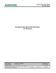
1.2 TSEV83<strong>10</strong>2G0B<br />
<strong>Evaluation</strong> <strong>Board</strong><br />
Figure 1-1. TSEV83<strong>10</strong>2G0B Block Diagram<br />
1-2 TSEV83<strong>10</strong>2G0B - <strong>Evaluation</strong> <strong>Board</strong> <strong>User</strong> <strong>Guide</strong><br />
2166D–BDC–01/04<br />
CLK<br />
Differential<br />
Clock inputs<br />
CLKB<br />
VIN<br />
Differential<br />
analog inputs<br />
VINB<br />
TEST<br />
CAL1<br />
CAL2<br />
VCC<br />
VEE<br />
GND<br />
DVEE<br />
GAIN<br />
SDA<br />
OA<br />
+5V<br />
-5V<br />
-5V<br />
Z0 = 50Ω<br />
Z0 = 50Ω<br />
Z0 = 50Ω<br />
Z0 = 50Ω<br />
VEE<br />
CLK<br />
CLKB<br />
VIN<br />
VINB<br />
GA<br />
PGEB<br />
SDA<br />
SDAEN<br />
TS83<strong>10</strong>2G0B<br />
DRRB<br />
VCC<br />
GND<br />
VPLUSD<br />
VEE<br />
DVEE<br />
DIODE<br />
L = 50 mm typ<br />
LVIN/VINb = LCLK/CLKb = 43 mm typ<br />
Loutputs = 58 mm typ<br />
Short-circuit<br />
possibility<br />
here<br />
DR/DRB<br />
D0/D0B<br />
D7/D7B<br />
PC/PCB<br />
VCC = +5V<br />
GND = 0V<br />
VEE<br />
Z0 = 50Ω<br />
Z0 = 50Ω<br />
Z0 = 50Ω<br />
Z0 = 50Ω<br />
VPLUSD = -0.8V (ECL)<br />
VPLUSD = 1.6V (LVDS)<br />
VEE = -5V<br />
DVEE = -5V<br />
DRRB<br />
B/BG<br />
J - diode<br />
V - diode<br />
V-GND<br />
I-GND
1.3 <strong>Board</strong><br />
Mechanical<br />
Characteristics<br />
Overview<br />
The board’s layer number, thickness, and functions are given below, from top to bottom.<br />
Table 1-1. <strong>Board</strong>’s Layer Thickness Profile<br />
Layer Characteristics<br />
Layer 1<br />
Copper layer<br />
Layer 2<br />
RO4003 dielectric layer<br />
(Hydrocarbon/Wovenglass)<br />
Layer 3<br />
Copper layer<br />
Layer 4<br />
BT/Epoxy dielectric layer<br />
Layer 5<br />
Copper layer<br />
Layer 6<br />
BT/Epoxy dielectric layer<br />
Layer 7<br />
Copper layer<br />
Layer 8<br />
BT/Epoxy dielectric layer<br />
Layer 9<br />
Copper layer<br />
Layer <strong>10</strong><br />
BT/Epoxy dielectric layer<br />
Layer 11<br />
Copper layer<br />
Copper thickness = 40 µm<br />
AC signal traces = 50Ω microstrip lines<br />
DC signal traces (B/GB, GAIN, DIODE, OA, TEST, SDA)<br />
Layer thickness = 200 µm<br />
Dielectric constant = 3.4 at <strong>10</strong> GHz<br />
-0.044 dB/inch insertion loss at 2.5 GHz<br />
-0.318 dB/inch insertion loss at 18 GHz<br />
Copper thickness = 39 µm<br />
Ground plane = reference plane 50Ω microstrip return<br />
Layer thickness = 330 µm<br />
Copper thickness = 35 µm<br />
Power and ground planes<br />
Layer thickness = 330 µm<br />
Copper thickness = 35 µm<br />
Power and ground planes (identical to layer 5)<br />
Layer thickness = 330 µm<br />
Copper thickness = 35 µm<br />
Ground planes (identical to layer 3)<br />
Layer thickness = 200 µm<br />
Copper thickness = 35 µm<br />
Power and ground planes<br />
The TSEV83<strong>10</strong>2G0B is an eleven layer PCB made of six copper layers and five dielectric<br />
layers. The six metal layers correspond respectively from top to bottom to the AC<br />
and DC signals layer (layer 1), two ground layers (layers 3 and 5), and one supply layer<br />
(layer 7).<br />
Considering the severe mechanical constraints due to the wide temperature range and<br />
the high frequency domain in which the board is to operate, it is necessary to use a<br />
sandwich of two different dielectric materials, with specific characteristics:<br />
� A low insertion loss RO4003 Hydrocarbon/Wovenglass dielectric layer of 200 µm<br />
thickness, chosen for its low loss (-0.318 dB/inch) and enhanced dielectric<br />
consistency in the high frequency domain. The RO4003 dielectric layer is dedicated to<br />
the routing of the 50Ω impedance signal traces (the RO4003 typical dielectric<br />
constant is 3.4 at <strong>10</strong> GHz). The RO4003 dielectric layer characteristics are very close<br />
to PTFE in terms of insertion loss characteristics.<br />
� A BT/Epoxy dielectric layer of 0.9 mm total thickness which is sandwiched between<br />
the upper ground plane and the back-side supply layer.<br />
TSEV83<strong>10</strong>2G0B - <strong>Evaluation</strong> <strong>Board</strong> <strong>User</strong> <strong>Guide</strong> 1-3<br />
2166D–BDC–01/04
Overview<br />
1.4 Analog Input,<br />
Clock Input and<br />
De-embedding<br />
Fixture Accesses<br />
1.5 Digital Outputs<br />
Accesses<br />
1.6 Power Supplies<br />
and Ground<br />
Accesses<br />
1.7 <strong>ADC</strong> Function<br />
Setting Accesses<br />
1-4 TSEV83<strong>10</strong>2G0B - <strong>Evaluation</strong> <strong>Board</strong> <strong>User</strong> <strong>Guide</strong><br />
2166D–BDC–01/04<br />
The BT/Epoxy layer has been chosen because of its enhanced mechanical characteristics<br />
for elevated temperature operation. The typical dielectric constant is 4.5 at 1 MHz.<br />
More precisely, the BT/Epoxy dielectric layer offers enhanced characteristics compared<br />
to FR4 Epoxy, namely:<br />
� Higher operating temperature values: 170° C (125° C for FR4).<br />
� Better withstanding of thermal shocks (-65° C up to 170° C).<br />
The total board thickness is 1.6 mm. The previously described mechanical and frequency<br />
characteristics makes the board particularly suitable for device evaluation and<br />
characterization in the high frequency domain and in military temperature ranges.<br />
The differential active inputs (Analog, Clock, De-embedding fixture) are provided by<br />
SMA connectors.<br />
Reference: VITELEC 142-0701-851.<br />
Connector mounting plates have been used for fastening the SMA connectors.<br />
Access to the differential output data port is provided by a 2.54 mm pitch connector,<br />
compatible with the high speed digital acquisition system. It enables access to the converter<br />
output data, as well as proper 50Ω differential termination.<br />
The power supply accesses are provided by five 2 mm section banana jacks respectively<br />
for DVEE , VEET , VDD , VPLUSD and VCC .<br />
The power supply access is provided by one 4 mm section banana jack for VEE .<br />
The Ground accesses are provided by four 2 mm and one 4 mm banana jacks.<br />
For <strong>ADC</strong> function setting accesses (B/GB, Die junction temp., Test), 2 mm section<br />
banana jacks are provided.<br />
Three potentiometers are provided for <strong>ADC</strong> gain adjust, Sampling delay adjust and Offset<br />
adjust.<br />
One sub-screw is provided for Asynchronous data ready reset.
Section 2<br />
Layout Information<br />
2.1 <strong>Board</strong> The TS83<strong>10</strong>2G0B requires proper board layout for optimum full speed operation.<br />
The following explains the board layout recommendations and demonstrates how the<br />
<strong>Evaluation</strong> <strong>Board</strong> fulfills these implementation constraints.<br />
A single low impedance ground plane is recommended, since it allows the user to lay<br />
out signal traces and power planes without interrupting the ground plane.<br />
Therefore a multi-layer board structure has been retained for the TSEV83<strong>10</strong>2G0B.<br />
Six copper metal layers are used, dedicated respectively (from top to bottom) to the signal<br />
traces, ground planes and power supplies.<br />
2.2 AC Inputs/Digital<br />
Outputs<br />
2.3 DC Function<br />
Settings<br />
The board uses 50Ω impedance microstrip lines for the differential analog inputs, clock<br />
inputs, and differential digital outputs.<br />
The input signals and clock signals must be routed on one layer only, without using any<br />
through-hole vias. The line lengths are matched to within 2 mm.<br />
The digital output lines are 50Ω differentially terminated.<br />
The output data trace lengths are matched to within 0.25 inch (6 mm) to minimize the<br />
data output delay skew.<br />
For the TSEV83<strong>10</strong>2G0B the propagation delay is approximately 6.1 ps/mm<br />
(155 ps/inch). The RO4003 typical dielectric constant is 3.4 at <strong>10</strong> GHz.<br />
For more informations about different output termination options refer to the specification<br />
application notes.<br />
The DC signal traces are low impedance.<br />
They have been routed with a 50Ω impedance near the device because of space<br />
restriction.<br />
TSEV83<strong>10</strong>2G0B - <strong>Evaluation</strong> <strong>Board</strong> <strong>User</strong> <strong>Guide</strong> 2-1<br />
Rev. 2166D–BDC–01/04
Layout Information<br />
2.4 Power Supplies The bottom metal layers 5 and 7 and 11 are dedicated to power supply traces (VEE, DVEE, VEET, VDD, VPLUSD and VCC). The supply traces are approximately 6 mm wide in order to present low impedance, and<br />
are surrounded by a ground plane connected to the two inner ground planes.<br />
The analog and digital negative power supply traces are independent, but the possibility<br />
exists to short-circuit both supplies on the top metal layer).<br />
No difference in <strong>ADC</strong> high speed performance is observed when connecting both negative<br />
supply planes together. Obviously one single negative supply plane could be used<br />
for the circuit.<br />
Each power supply incoming is bypassed by a 1 µF Tantalum capacitor in parallel with<br />
1 nF chip capacitor.<br />
Each power supply access is decoupled very close to the device by <strong>10</strong> nF and <strong>10</strong>0 pF<br />
surface mount chip capacitors in parallel.<br />
Note: The decoupling capacitors are superposed. In this configuration, the <strong>10</strong>0 pF capacitors<br />
must be mounted first.<br />
2-2 TSEV83<strong>10</strong>2G0B - <strong>Evaluation</strong> <strong>Board</strong> <strong>User</strong> <strong>Guide</strong><br />
2166D–BDC–01/04
Section 3<br />
Operating Procedures and<br />
Characteristics<br />
3.1 Introduction This section describes a typical single-ended configuration for analog inputs and clock<br />
inputs.<br />
The single-ended configuration is preferable, as it corresponds to the most straightforward<br />
and quickest TSEV83<strong>10</strong>2G0B board setting for evaluating the TS83<strong>10</strong>2G0B at full<br />
speed in its temperature range.<br />
The inverted analog input VINB and clock input CLKB common mode level is Ground<br />
(on-chip 50Ω terminated). In this configuration, no balun transformer is needed to convert<br />
properly the single-ended mixer output to balanced differential signals for the<br />
analog inputs.<br />
In the same way, no balun is necessary to feed the TS83<strong>10</strong>2G0B clock inputs with balanced<br />
signals.<br />
Directly connect the RF sources to the in-phase analog and clock inputs of the<br />
converter.<br />
However, dynamic performances can be somewhat improved by entering either analog<br />
or clock inputs in differential mode.<br />
3.2 Operating<br />
Procedure (ECL<br />
Mode)<br />
1. Connect the power supplies and Ground accesses<br />
(V CC = +5V, GND = 0V, V PLUSD = 0V, V EE = DV EE = -5V) through the dedicated<br />
banana jacks.<br />
The -5V power supplies should be turned on first.<br />
Note: one single -5V power supply can be used for supplying the digital DV EE and<br />
analog V EE power planes.<br />
2. The board is set by default for digital outputs in binary format.<br />
3. Connect the CLK clock signal.<br />
The inverted phase clock input CLKB may be left open (as on-chip 50Ω terminated).<br />
Use a low phase noise RF source. The clock input level is typically<br />
4 dBm and should not exceed +<strong>10</strong> dBm into the 50Ω termination resistor (maximum<br />
ratings for the clock input power level is 15 dBm).<br />
TSEV83<strong>10</strong>2G0B - <strong>Evaluation</strong> <strong>Board</strong> <strong>User</strong> <strong>Guide</strong> 3-1<br />
Rev. 2166D–BDC–01/04
Operating Procedures and Characteristics<br />
3.3 Use with DMUX<br />
<strong>Evaluation</strong> <strong>Board</strong><br />
3-2 TSEV83<strong>10</strong>2G0B - <strong>Evaluation</strong> <strong>Board</strong> <strong>User</strong> <strong>Guide</strong><br />
2166D–BDC–01/04<br />
4. Connect the analog signal V IN . The inverted phase clock input V INB may be left<br />
open (as on cavity 50Ω terminated). Use a low phase noise RF source. Full<br />
scale range is 0.5V peak to peak around 0V, (±250 mV), or -2 dBm into 50Ω.<br />
Input frequency can range from DC up to 1.8 GHz. At 3.0 GHz, the <strong>ADC</strong> attenuates<br />
the input signal by -3 dB. The board insertion loss (S21) will be furnished in<br />
the definitive document release.<br />
5. Connect the high speed data acquisition system probes to the output connector.<br />
The connector pitch (2.54 mm) is compatible with high speed digital acquisition<br />
system probes. The digital data are on-board differentially terminated. However,<br />
the output data can be picked up either in single-ended or differential mode.<br />
The TSEV81<strong>10</strong>2G0 DMUX evaluation board has been designed to be fully compatible<br />
with the TSEV83<strong>10</strong>2G0B <strong>ADC</strong> evaluation board.<br />
The DEMUX input configuration has been optimized to be connected to the<br />
TS83<strong>10</strong>2G0B <strong>ADC</strong> (CBGA152 package).<br />
When using the DEMUX board with the <strong>ADC</strong> board, do not forget to set, for proper use,<br />
CLKINTYPE in mode DR/2 (jumper on-board).<br />
The power-up sequence should be:<br />
1. Supply the <strong>ADC</strong> first<br />
2. Supply the DMUX<br />
3. Perform an asynchronous reset on the DMUX board<br />
When this power up sequence has been completed, the synchronization between the<br />
DEMUX and <strong>ADC</strong> boards can be achieved via the DEMUXDelADjCtrl potentiometer on<br />
the DEMUX evaluation board. To achieve a good synchronization between the two<br />
boards, it is recommended to run the <strong>ADC</strong> at its full speed (max sampling rate) and tune<br />
the DEMUX Delay Adjust Control potentiometer to the left and take down the settings for<br />
which the boards are de-synchronized and similarly to the right to see the loss of synchronization<br />
at the other extremity. The right setting of the potentiometer is in the middle<br />
of these two settings and should be right for all sampling rates of the <strong>ADC</strong>.<br />
Please refer to the "<strong>ADC</strong>s and Demux Application Notes" document for more<br />
information.
3.4 Electrical<br />
Characteristics<br />
Table 3-1. Absolute Maximum Ratings<br />
Operating Procedures and Characteristics<br />
Parameter Symbol Comments Value Unit<br />
Positive supply voltage V CC GND to 5.5 V<br />
Digital negative supply voltage DV EE GND to -5.5 V<br />
Digital positive supply voltage V PLUSD GND -1.1 to 2.0 V<br />
Negative supply voltage V EE GND to -5.5 V<br />
Maximum difference between negative supply voltages DV EE to V EE 0.3 V<br />
Analog input voltages V IN or V INB -1.5 to +1.5 V<br />
Maximum difference between V IN and V INB V IN - V INB -1.5 to +1.5 V<br />
Clock input voltage V CLK or V CLKB -1 to +1 V<br />
Maximum difference between V CLK and V CLKB V CLK - V CLKB -1 to +1 V<br />
Static input voltage VD GA/SDA -5 to +0.8 V<br />
Digital input voltage VD SDAEN, DRRB,<br />
B/GB, PGEB<br />
-5 to +0.8 V<br />
Digital output voltage VO VPLUSD -2.2 to VPLUSD +0.3 V<br />
Maximum junction temperature T j +125 ° C<br />
Storage temperature T stg -65 to +150 ° C<br />
Lead temperature (soldering <strong>10</strong>s) Tleads +300 ° C<br />
Note: Absolute maximum ratings are limiting values (referenced to GND = 0V), to be applied individually, while other parameters are<br />
within specified operating conditions. Long exposure to maximum rating may affect device reliability. The use of a thermal heat<br />
sink is mandatory.<br />
TSEV83<strong>10</strong>2G0B - <strong>Evaluation</strong> <strong>Board</strong> <strong>User</strong> <strong>Guide</strong> 3-3<br />
2166D–BDC–01/04
Operating Procedures and Characteristics<br />
3.5 Operating<br />
Characteristics<br />
Table 3-2. Electrical Operating Characteristics<br />
Parameter Symbol<br />
Positive supply voltage<br />
(dedicated to TS83<strong>10</strong>2G0B <strong>ADC</strong> only)<br />
Positive supply current<br />
(dedicated to TS83<strong>10</strong>2G0B <strong>ADC</strong> only)<br />
Positive supply voltage not used by default – installed<br />
(dedicated to MC<strong>10</strong>0EL16 differential receivers)<br />
Positive supply current not used by default – installed<br />
(dedicated to MC<strong>10</strong>0EL16 differential receivers)<br />
3-4 TSEV83<strong>10</strong>2G0B - <strong>Evaluation</strong> <strong>Board</strong> <strong>User</strong> <strong>Guide</strong><br />
2166D–BDC–01/04<br />
The power supplies denoted by VCC, VEE, DVEE and VPLUSD are dedicated to the<br />
TS83<strong>10</strong>2G0B <strong>ADC</strong>.<br />
The power supplies denoted VEET, VDD are dedicated to the optional MC<strong>10</strong>0EL16 asynchronous<br />
differential receivers.<br />
Value<br />
Min Typ Max<br />
V CC 4.75 5 5.25 V<br />
V PLUSD<br />
–<br />
ECL: -0.8<br />
LVDS: 1.6<br />
V EEA -5.25 -5 -4.75 V<br />
V EED -5.25 -5 -4.75 V<br />
–<br />
Unit<br />
I CC – 144 205 mA<br />
I PLUSD – 164 – mA<br />
I EEA – 514 630 mA<br />
I EED – 170 180 mA<br />
V EET -5.25 -5 -4.75 V<br />
V DD -2.15 -2 -185 V<br />
I EET – 180 – mA<br />
I DD – 480 – mA<br />
Nominal power dissipation (without receivers) PD – 4.6<br />
5.1<br />
(TJ = 125° C)<br />
W<br />
Analog input impedance ZIN – 50 – Ω<br />
Full power analog input bandwidth (-3 dB) – – 3.0 – GHz<br />
Analog input voltage range (differential mode) V IN -125 – 125 mV<br />
Clock input impedance – – 50 – Ω<br />
Clock input voltage compatibility (single-ended or<br />
differential) (See Application Notes)<br />
– ECL levels or 4 dBm (typ) into 50Ω –<br />
Clock input power level into 50Ω termination resistor – -2 2 4 dBm<br />
V<br />
V
Section 4<br />
Application Information<br />
4.1 Introduction For this section, also refer to the product "Main features" (TS83<strong>10</strong>2G0B Datasheet).<br />
More particularly, refer to sections related to single-ended and differential input<br />
configurations.<br />
4.2 Analog Inputs The analog inputs can be entered in differential or single-ended mode without any high<br />
speed performance degradation.<br />
The board digitizes single-ended signals by choosing either input and leaving the other<br />
input open, as the latter is on-board 50Ω terminated. The nominal in-phase inputs are<br />
VIN (See Section 3).<br />
4.3 Clock Inputs The clock inputs can be entered in differential or single-ended mode without any performance<br />
degradation for a clock frequency up to 500 MHz. At higher rates, it is<br />
recommended to drive the clock inputs differentially. Moreover, the typical in phase<br />
clock input amplitude is 1V peak to peak, centered on 0V (Ground), or -1.3V (ECL) on<br />
common mode.<br />
As for the analog input, either clock input can be chosen (if the single-ended output<br />
mode is used), leaving the other input open, as both clock inputs are on-chip 50Ω terminated.<br />
The nominal in-phase clock input is CLK (Section 3).<br />
4.4 Setting the<br />
Digital Output<br />
Data Format<br />
For this section, refer to the <strong>Evaluation</strong> <strong>Board</strong> Electrical schematic and to the components<br />
placement document (respectively Figure 6-2 on page 6-3 and Figure 6-8 on page<br />
6-4).<br />
Refer also to the TS83<strong>10</strong>2G0B specification about digital output coding.<br />
The TS83<strong>10</strong>2G0B delivers data in natural binary code or in Gray code. If the B/GB input<br />
is left floating or tied to GND the data format selected will be natural binary, if this input<br />
is tied to VEE the data will follow the Gray code.<br />
Use the jumper denoted B/GB to select the output data port format:<br />
� If B/GB is left floating or tied to GND, the data output format is true binary.<br />
� If B/GB is tied to V EE or driven with ECL low level, the data outputs are in the Gray<br />
format.<br />
TSEV83<strong>10</strong>2G0B - <strong>Evaluation</strong> <strong>Board</strong> <strong>User</strong> <strong>Guide</strong> 4-1<br />
Rev. 2166D–BDC–01/04
Application Information<br />
4-2 TSEV83<strong>10</strong>2G0B - <strong>Evaluation</strong> <strong>Board</strong> <strong>User</strong> <strong>Guide</strong><br />
2166D–BDC–01/04<br />
The VPLUSD positive supply voltage allows the adjustment of the output common mode<br />
level from -1.05V (VPLUSD = -0.8V for ECL output compatibility) to +1.35V (VPLUSD = 1.6V<br />
for LVDS output compatibility).<br />
Each output voltage varies between -0.9V and -1.2V (respectively +1.2V and +1.5V),<br />
leading to ±0.3V = 660 mV in differential for VPLUSD = -0.8V (respectively 1.6V).<br />
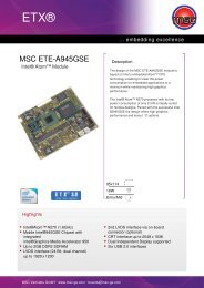
4.5 <strong>ADC</strong> Gain Adjust The <strong>ADC</strong> gain is adjustable by the means of pin R9 (pad input impedance is 1 MΩ in<br />
parallel with 2 pF). A jumper denoted GAIN has been foreseen in order to have access<br />
to the <strong>ADC</strong> gain adjust pin.<br />
The GAIN potentiometer is dedicated to adjusting the <strong>ADC</strong> gain from approximately<br />
0.85 up to 1.15.<br />
The gain adjust transfer function is given below.<br />
4.6 SMA Connectors<br />
and Microstrip<br />
Lines Deembedding<br />
Fixture<br />
Figure 4-1. <strong>ADC</strong> Gain Adjust<br />
<strong>ADC</strong> Gain<br />
1.20<br />
1.15<br />
1.<strong>10</strong><br />
1.05<br />
1.00<br />
0.95<br />
0.90<br />
0.85<br />
0.80<br />
-600 -400 -200 0 200 400 600<br />
Vgain (command voltage) (mV)<br />
Attenuation in microstrip lines can be found by taking the difference in the log magnitudes<br />
of the S21 scattering parameters measured on two different lengths of<br />
meandering transmission lines.<br />
Such a measurement also removes common losses such as those due to transitions<br />
and connectors.<br />
The S21 scattering parameter corresponds to the amount of power transmitted through<br />
a two-port network.<br />
The characteristic impedance of the microstrip meander lines must be close to 50Ω to<br />
minimize impedance mismatch with the 50Ω network analyzer test ports.<br />
Impedance mismatch will cause ripples in the S21 parameter as a function of both the<br />
degree of mismatch and the length of the line.
4.7 Die Junction<br />
Temperature<br />
Monitoring<br />
Application Information<br />
Figure 4-2 and Figure 4-3 illustrate the recommanded implementation of the die junction<br />
temperature monitoring function for the Revision B of the <strong>10</strong>-<strong>bit</strong> 2 <strong>Gsps</strong> <strong>ADC</strong>.<br />
The user has the choice between two possible configurations:<br />
1. The <strong>ADC</strong> decimation test mode is NOT ALLOWED.<br />
Because of the use of 1 internal diode-mounted transistors, the user has to implement<br />
2 x 2 head-to-tail protection diodes to avoid potential reverse current flows to damage<br />
the diode pin.<br />
Note that Atmel usually recommends the use of 2 x 3 head-to-tail protection diodes but<br />
in this particular case, it is necessary to have exactly 2 diodes in the A<strong>10</strong> to ground<br />
direction of conduction.<br />
Figure 4-2. Recommended Die Junction Temperature Monitoring Function Implementation,<br />
Test Mode Not Allowed<br />
<strong>ADC</strong> Pin<br />
A<strong>10</strong><br />
2. The <strong>ADC</strong> test mode can be allowed<br />
In case the user wants to still be able to switch from the normal mode to the test mode or<br />
to the die junction temperature monitoring, the protection diode configuration is slightly<br />
different and takes into account the fact that the test mode can be activated by applying<br />
VEE = -5V to the diode pin.<br />
This explains why 7 protection diodes are needed in the other direction, as described in<br />
Figure 4-3.<br />
Figure 4-3. Recommended Diode Pin Implementation Allowing for Both Die Junction<br />
Temperature Monitoring Function and Test Mode<br />
TSEV83<strong>10</strong>2G0B - <strong>Evaluation</strong> <strong>Board</strong> <strong>User</strong> <strong>Guide</strong> 4-3<br />
GND<br />
<strong>ADC</strong> Pin<br />
A<strong>10</strong><br />
GND<br />
IGND<br />
Idiode<br />
Vdiode<br />
VGND<br />
IGND<br />
Idiode<br />
Vdiode<br />
VGND<br />
V<br />
V<br />
1 mA<br />
1 mA<br />
2166D–BDC–01/04
Application Information<br />
4-4 TSEV83<strong>10</strong>2G0B - <strong>Evaluation</strong> <strong>Board</strong> <strong>User</strong> <strong>Guide</strong><br />
2166D–BDC–01/04<br />
For Revision B, the VDIODE characteristic corresponds to a single diode characteristic<br />
over temperature, thus starting at 0.9V, as illustrated in Figure 4-4, which is only an<br />
interpolated VDIODE characteristic (to be confirmed by future measurements).<br />
This modification in Revision B devices implies the modification of the processing of the<br />
VDIODE characteristic if any but above all, it allows the user to implement a digital temperature<br />
sensor to be interfaced with the ASIC (DSP, FPGA, etc...) loading the <strong>ADC</strong>.<br />
Figure 4-4. Diode Pin Implementation in Test Mode<br />
A typical configuration with a standard digital temperature sensor is depicted in<br />
Figure 4-5.<br />
Figure 4-5. Typical Configuration with a Digital Temperature Sensor<br />
A<strong>10</strong><br />
GND<br />
<strong>ADC</strong> Pin<br />
A<strong>10</strong><br />
GND<br />
DXT<br />
DXN<br />
Temperature<br />
Sensor<br />
VEE = -5V
4.8 Decimation<br />
Function<br />
4.9 Pattern<br />
Generator<br />
Enable<br />
Application Information<br />
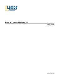
The expected diode mounted transistors V DIODE value (including chip parasitic resistance)<br />
versus junction temperature is given in Figure 4-6 (I DIODE = 1 mA).<br />
Figure 4-6. Junction Temperature Versus Diode Voltage for I = 1 mA<br />
Diode Voltage (mV)<br />
940<br />
930<br />
920<br />
9<strong>10</strong><br />
900<br />
890<br />
880<br />
870<br />
860<br />
850<br />
840<br />
830<br />
820<br />
8<strong>10</strong><br />
800<br />
790<br />
-<strong>10</strong> 0 <strong>10</strong> 20 30 40 50 60 70 80 90 <strong>10</strong>0 1<strong>10</strong><br />
Junction Temperature (°C)<br />
Note: The operating die junction temperature must be kept below 125° C; therefore, an adequate<br />
cooling system has to be set up.<br />
The decimation function can be used for debug of the <strong>ADC</strong> at initial stages. This function<br />
indeed allows to reduce the <strong>ADC</strong> output rate by 32, thus allowing for a quick debug<br />
phase of the <strong>ADC</strong> at maximum speed rate.<br />
When active, this fuction makes the <strong>ADC</strong> output only 1 out of 32 data, thus resulting in a<br />
data rate which is 32 times slower than the clock rate.<br />
The TS83<strong>10</strong>2G0B is able to generate by itself (without any analog input signal) a serie<br />
of patterns. If the TEST input is left floating or tied to GND the TS83<strong>10</strong>2G0B will digitize<br />
the analog input signal according to B/GB. If this input is driven with ECL low level or<br />
tied to VEE, TS83<strong>10</strong>2G0B will generate Checker <strong>Board</strong> patterns.<br />
Use the jumper denoted TEST for enabling the pattern generator.<br />
TSEV83<strong>10</strong>2G0B - <strong>Evaluation</strong> <strong>Board</strong> <strong>User</strong> <strong>Guide</strong> 4-5<br />
2166D–BDC–01/04
Application Information<br />
4.<strong>10</strong> Data Ready<br />
Output Signal<br />
Reset<br />
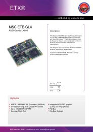
4.11 Sampling Delay<br />
Adjusting<br />
Figure 4-7. Sampling Delay Adjust<br />
Delay<br />
400p<br />
300p<br />
200p<br />
4-6 TSEV83<strong>10</strong>2G0B - <strong>Evaluation</strong> <strong>Board</strong> <strong>User</strong> <strong>Guide</strong><br />
2166D–BDC–01/04<br />
A sub-screw connector is provided for the DRRB command.<br />
The Data Ready signal is reset on the falling edge of the DRRB input command, on ECL<br />
logical low level (-1.8V). DRRB may also be tied to VEE = -5V for Data Ready output signal<br />
master reset. As long as DRRB remains at a logical low level, (or tied to VEE = -5V),<br />
the Data Ready output remains at logical zero and is independent of the external free<br />
running encoding clock.<br />
The Data Ready output signal (DR, DRB) is reset to logical zero after TRDR = 720 ps<br />
typically.<br />
TRDR is measured between the -1.3V point of the falling edge of the DRRB input command<br />
and the zero crossing point of the differential Data Ready output signal (DR,<br />
DRB).<br />
The Data Ready Reset command may be a pulse of 1 ns minimum time width.<br />
The Data Ready output signal restarts on the DRRB command rising edge, ECL logical<br />
high levels (-0.8V).<br />
DRRB may also be grounded, or is allowed to float, for normal free running of the Data<br />
Ready output signal.<br />
One delay adjust, controlled by SDA potentiometer, is available in order to add a delay<br />
to the input clock of the <strong>ADC</strong>. This allows the user to tune the instant of the internal sampling.<br />
To enable this delay adjustment there is an SDAEN pin on the chip. In the current<br />
revision, the SDAEN function corresponds to the OA labels (OA jumper and OA<br />
potentiometer).<br />
The OA potentiometer has been removed and short-circuited to VEE. Use the jumper denoted OA to enable the sampling delay adjustment:<br />
� If OA is left floating or tied to GND, the SDA is disabled<br />
� If OA is tied to V EE , the SDA is enabled<br />
The SDA input varies from -0.5 to 0.5V, according to the SDA potentiometer position.<br />
The variation of the delay around its nominal value as a function of the SDA voltage is<br />
more or less linear, as shown in Figure 4-7 (simulation results).<br />
: (cross(clip((VT("delop") - VT("delon")) 4e-<strong>10</strong> 2e-09) 0 2 "rising") - cross(clip((VT("delip") - VT("delin")) 2.5e-<strong>10</strong> 2e-09) 0 2 "rising")) (60°C)<br />
Delay in the variable delay cell at 60°C<br />
<strong>10</strong>0p<br />
-500m -400m -300m -200m -<strong>10</strong>0m 0m<br />
SDAVAL<br />
<strong>10</strong>0m<br />
200m 300m 400m 500m<br />
Note: The variation of the delay as a function of temperature is insignificant.
4.12 Test Bench<br />
Description<br />
Figure 4-8. Differential Analog and Clock Input Configuration<br />
Synchro <strong>10</strong> MHz<br />
Figure 4-9. Single-ended Analog and Clock Input Configuration<br />
Synchro <strong>10</strong> MHz<br />
RF Generator<br />
-121 dBc/Hz at 1 KHz<br />
offset from fc<br />
RF Generator<br />
-117 dBc/Hz at 20 KHz<br />
offset from fc<br />
GPIB<br />
Data Acquisition<br />
System<br />
PC<br />
Data Acquisition<br />
System<br />
GPIB<br />
RF Generator<br />
RF Generator<br />
PC<br />
0 − 180°<br />
Hybrid<br />
Application Information<br />
0 − 180°<br />
Hybrid<br />
TSEV83<strong>10</strong>2G0B - <strong>Evaluation</strong> <strong>Board</strong> <strong>User</strong> <strong>Guide</strong> 4-7<br />
BPF<br />
<strong>10</strong> Data<br />
BPF<br />
<strong>10</strong> Data<br />
DR<br />
CLKB CLK<br />
TS83<strong>10</strong>2G0B<br />
<strong>ADC</strong><br />
Tunable delay line<br />
(50Ω) CLKB CLK<br />
DR<br />
TS83<strong>10</strong>2G0B<br />
<strong>ADC</strong><br />
Tunable delay line<br />
VINB<br />
VIN<br />
VINB (50Ω)<br />
VIN<br />
2166D–BDC–01/04
Application Information<br />
4-8 TSEV83<strong>10</strong>2G0B - <strong>Evaluation</strong> <strong>Board</strong> <strong>User</strong> <strong>Guide</strong><br />
2166D–BDC–01/04
5.1 TS83<strong>10</strong>2G0B<br />
Pinout<br />
Figure 5-1. TS83<strong>10</strong>2G0B Pinout of CBGA152 Package<br />
16<br />
15<br />
14<br />
13<br />
12<br />
11<br />
<strong>10</strong><br />
9<br />
8<br />
7<br />
6<br />
5<br />
4<br />
3<br />
2<br />
1<br />
Section 5<br />
Package Description<br />
A B C D E F G H J K L M N P Q R<br />
NC<br />
GND<br />
DVEE<br />
VPLUSD<br />
B/GB<br />
DECB/<br />
DIODE<br />
GND GND VPLUSD VPLUSD VPLUSD GND DVEE DVEE GND VPLUSD VPLUSD VPLUSD GND GND<br />
DVEE DVEE DVEE DVEE<br />
VPLUSD VPLUSD GND VPLUSD<br />
GND VPLUSD VPLUSD VPLUSD<br />
GND VEE VPLUSD VEE<br />
PGEB GND VEE VEE VEE<br />
VEE<br />
VCC<br />
SDA<br />
GND<br />
VEE<br />
GND<br />
GND OR D0 D1 D2 D3 DR D4 D5 D6 D7 D8 D9 GND<br />
GND ORB D0B D1B D2B D3B DRB D4B D5B D6B D7B D8B D9B GND<br />
VEE VEE VCC VCC<br />
VCC VCC GND GND<br />
VCC<br />
VEE<br />
TS83<strong>10</strong>2G0B<br />
CBGA152<br />
(cavity down)<br />
VCC GND<br />
VEE GND<br />
VEE VEE GND GND GND<br />
GND VEE GND GND GND GND VEEH VCCTH VCCTH VEE VEE GND VEE VEE VEE<br />
NC GND GND GND GND GND GND VEEH VEEH VCCTH<br />
VEE VEE GND<br />
Note: If required, four NC balls can be electrically connected to GND to simplify PCB routing.<br />
TSEV83<strong>10</strong>2G0B - <strong>Evaluation</strong> <strong>Board</strong> <strong>User</strong> <strong>Guide</strong> 5-1<br />
GND<br />
GND<br />
NC<br />
GND<br />
DVEE<br />
VPLUSD<br />
GND<br />
VEE<br />
GA<br />
VCC<br />
GND<br />
VINb<br />
VIN<br />
GND GND NC<br />
GND GND GND CLK CLKb GND VEEH VEEH VCCTH VEE GND DRRB SDAEN GND<br />
A B C D E F G H J K L M N P Q R<br />
16<br />
15<br />
14<br />
13<br />
12<br />
11<br />
<strong>10</strong><br />
9<br />
8<br />
7<br />
6<br />
5<br />
4<br />
3<br />
2<br />
1<br />
Rev. 2166D–BDC–01/04
Package Description<br />
Table 5-1. TSEV83<strong>10</strong>2G0B Pin Description<br />
Symbol Pin Number Function<br />
Power Supplies<br />
V CC K1, K2, J3, K3, B6, C6, A7, B7, C7, P8, Q8, R8 +5V analog supply<br />
GND<br />
V EE<br />
5-2 TSEV83<strong>10</strong>2G0B - <strong>Evaluation</strong> <strong>Board</strong> <strong>User</strong> <strong>Guide</strong><br />
2166D–BDC–01/04<br />
B1, C1, D1, G1, M1, Q1, B2, C2, D2, E2, F2,<br />
G2, N2, P2, Q2, A3, B3, D3, E3, F3, G3, N3,<br />
P4, Q4, R4, A5, P5, Q5, P6, Q6, P7, Q7, R7,<br />
B9, B<strong>10</strong>, B11, R11, P12, A14, B14, C14, G14,<br />
K14, P14, Q14, R14, B15, Q15, B16, Q16<br />
H1, J1, L1, H2, J2, L2, M2, C3, H3, L3, M3, P3,<br />
Q3, R3, A4, B4, C4, B5, C5, A8, B8, C8, C9,<br />
P9, Q9, C<strong>10</strong>, Q<strong>10</strong>, R<strong>10</strong><br />
Analog ground<br />
-5V analog supply<br />
VPLUSD P<strong>10</strong>, C11, P11, Q11, A12, B12, C12, Q12,<br />
R12, D14, E14, F14, L14, M14, N14<br />
Digital positive supply<br />
DVEE A13, B13, C13, P13, Q13, R13, H14, J14 -5V digital supply<br />
Analog Inputs<br />
V IN<br />
V INB<br />
Clock Inputs<br />
R5<br />
R6<br />
CLK E1 In-phase (+) clock input<br />
In-phase (+) analog input signal of the differential sample<br />
and hold preamplifier<br />
Inverted phase (-) analog input signal of the differential<br />
sample and hold preamplifier<br />
CLKB F1 Inverted phase (-) clock input<br />
Digital outputs<br />
D0, D1, D2, D3, D4,<br />
D5, D6, D7, D8, D9<br />
D0B, D1B, D2B, D3B,<br />
D4B, D5B, D6B, D7B,<br />
D8B, D9B<br />
D16, E16, F16, G16, J16, K16, L16, M16, N16,<br />
P16<br />
D15, E15, F15, G15, J15, K15, L15, M15, N15,<br />
P15<br />
In-phase (+) digital outputs<br />
D0 is the LSB. D9 is the MSB<br />
Inverted phase (-) digital outputs<br />
OR C16 In-phase (+) Out-of-Range output<br />
ORB C15 Inverted phase (-) Out-of-Range output<br />
DR H16 In-phase (+) Data Ready Signal output<br />
DRB H15 Inverted phase (-) Data Ready Signal output<br />
Additional Functions<br />
B/GB A11<br />
Binary or Gray select output format control<br />
- Binary output format if B/GB is floating or connected to<br />
GND<br />
- Gray output format if B/GB is driven with ECL low level or<br />
B/GB is connected to V EE
Table 5-1. TSEV83<strong>10</strong>2G0B Pin Description (Continued)<br />
Symbol Pin Number Function<br />
DIODE A<strong>10</strong><br />
PGEB A9<br />
5.2 Thermal<br />
Characteristics<br />
5.2.1 Thermal Resistance<br />
from Junction to<br />
Ambient: Rthja<br />
Package Description<br />
Decimation function enable or die junction temperature<br />
monitoring:<br />
- Decimation active when LOW (die junction temperature<br />
monitoring NOT possible)<br />
- Normal mode when HIGH or left floating<br />
- Die junction temperature monitoring when current is<br />
applied<br />
Active low pattern generator enable<br />
- Digitized input delivered at outputs according to B/GB if<br />
PGEB is floating or connected to GND<br />
- Checkerboard pattern delivered at outputs if PGEB is<br />
driven with ECL low level or connected to V EE<br />
DRRB N1 Asynchronous Data Ready Reset function<br />
GA R9 Gain Adjust<br />
SDA A6 Sampling delay adjust<br />
SDAEN P1<br />
Table 5-2. Thermal Resistance<br />
Sampling delay adjust enable:<br />
- inactive if floating or connected to GND<br />
- active if ECL low or connected to V EE<br />
Table 5-2 lists the converter’s thermal performance parameters of the device itself, with<br />
no external heatsink added.<br />
Air Flow (m/s)<br />
Estimated ja Thermal<br />
Resistance (° C/W)<br />
0 45 Figure 5-2. Thermal Resistance from Junction to Ambient: Rthja<br />
0.5 35.8<br />
1 30.8<br />
1.5 27.4<br />
2 24.9<br />
2.5 23<br />
3 21.5<br />
4 19.3<br />
5 17.7<br />
TSEV83<strong>10</strong>2G0B - <strong>Evaluation</strong> <strong>Board</strong> <strong>User</strong> <strong>Guide</strong> 5-3<br />
Rthja (°C/W)<br />
50<br />
40<br />
30<br />
20<br />
<strong>10</strong><br />
0<br />
0<br />
1 2 3 4 5<br />
Air flow (m/s)<br />
2166D–BDC–01/04
Package Description<br />
5.2.2 Thermal Resistance<br />
from Junction to<br />
Case: Rthjc<br />
5-4 TSEV83<strong>10</strong>2G0B - <strong>Evaluation</strong> <strong>Board</strong> <strong>User</strong> <strong>Guide</strong><br />
2166D–BDC–01/04<br />
Maximum thermal Junction to Case resistance is 4.0° C/Watt.<br />
This value does not include thermal contact resistance between the package and external<br />
heatsink (glue, paste, or thermal foil interface for example).<br />
As an example, we can take 2.0° C/W for 50 µm thickness of thermal grease.<br />
5.2.3 Heatsink It is recommended to use a 50 mm x 50 mm x 30 mm heatsink (respectively L x l x H) in<br />
case of natural convection cooling mode (with no air flow).<br />
A fan heatsink or direct conduction cooling is recommended, due to high power dissipation<br />
(4.7W).<br />
A method should be chosen for cooling that allows less than 4.0° C/W for the case to<br />
ambient thermal resistance (Rthca).<br />
The thermal resistance of the board is a high value (within a range of 30° C/W); thus an<br />
external heatsink is mandatory.<br />
The heatsink must be fixed to the heatspreader which is at -5V. So the heatsink needs<br />
to be electrically isolated; using adequate low Rth electrical isolation.<br />
Example: 4.0° C/W Rthca (case to ambient) +2.0° C/W thermal grease resistance<br />
+4.0° C/W Rthjc = <strong>10</strong>.0° C/W total (Rthja).<br />
The heatsink should make contact with the package on the side opposite to the balls, in<br />
a 8.5 mm diameter circle:<br />
Figure 5-3. CBGA152 <strong>Board</strong> Assembly<br />
24.2<br />
20.2<br />
Note: The measures are given in mm.<br />
50.5<br />
Cooling system efficiency can be monitored using the Temperature Sensing Diodes,<br />
integrated in the device.<br />
8.5<br />
31<br />
<strong>Board</strong><br />
32.5
5.3 Ordering<br />
Information<br />
Package Description<br />
Part Number Package Temperature Range Screening Level Comments<br />
JTSX83<strong>10</strong>2G0-1V1B Die Ambient Prototype<br />
ON REQUEST ONLY<br />
(Please contact Marketing)<br />
TSX83<strong>10</strong>2G0BGL CBGA 152 Ambient Prototype Prototype Version<br />
TS83<strong>10</strong>2G0BCGL CBGA 152<br />
TS83<strong>10</strong>2G0BVGL CBGA 152<br />
“C” grade:<br />
0° C < T C; T J < 90° C<br />
“V” grade:<br />
-20° C < T C ; T J < 1<strong>10</strong>° C<br />
Standard<br />
Standard<br />
TSEV83<strong>10</strong>2G0BGL CBGA 152 Ambient Prototype<br />
<strong>Evaluation</strong> <strong>Board</strong><br />
(delivered with heatsink)<br />
TSEV83<strong>10</strong>2G0B - <strong>Evaluation</strong> <strong>Board</strong> <strong>User</strong> <strong>Guide</strong> 5-5<br />
2166D–BDC–01/04
Package Description<br />
5-6 TSEV83<strong>10</strong>2G0B - <strong>Evaluation</strong> <strong>Board</strong> <strong>User</strong> <strong>Guide</strong><br />
2166D–BDC–01/04
6.1 TSEV83<strong>10</strong>2G0B<br />
Electrical<br />
Schematic<br />
Section 6<br />
Schematics<br />
Figures 6-2 to Figures 6-8 shows the electrical schematic of the TSEV83<strong>10</strong>2G0B.<br />
The pinout used for the evaluation board has been translated from Atmel's pinout (refer<br />
to page 5-1) to the JEDEC standard shown in Figure 6-1. This explains the discrepancies<br />
between the pinout used on page 5-1 and the one given in the electrical schematic<br />
in Figure 6-2.<br />
TSEV83<strong>10</strong>2G0B - <strong>Evaluation</strong> <strong>Board</strong> <strong>User</strong> <strong>Guide</strong> 6-1<br />
Rev. 2166D–BDC–01/04
Schematics<br />
Figure 6-1. TS83<strong>10</strong>2G0B pinout in JEDEC Standard<br />
1 2 3 4 5 6 7 8 9 <strong>10</strong> 11 12 13 14 15 16<br />
6-2 TSEV83<strong>10</strong>2G0B - <strong>Evaluation</strong> <strong>Board</strong> <strong>User</strong> <strong>Guide</strong><br />
2166D–BDC–01/04<br />
R<br />
Q<br />
P<br />
N<br />
M<br />
L<br />
K<br />
J<br />
H<br />
G<br />
F<br />
E<br />
D<br />
C<br />
B<br />
A<br />
NC<br />
GND<br />
DVEE<br />
VPLUSD<br />
B/GB<br />
DECB/<br />
DIODE<br />
GND GND VPLUSD VPLUSD VPLUSD GND DVEE DVEE GND VPLUSD VPLUSD VPLUSD GND GND<br />
DVEE DVEE DVEE DVEE<br />
VPLUSD VPLUSD GND VPLUSD<br />
GND VPLUSD VPLUSD VPLUSD<br />
GND VEE VPLUSD VEE<br />
PGEB GND VEE VEE VEE<br />
VEE<br />
VCC<br />
SDA<br />
GND<br />
VEE<br />
GND<br />
GND OR D0 D1 D2 D3 DR D4 D5 D6 D7 D8 D9 GND<br />
GND ORB D0B D1B D2B D3B DRB D4B D5B D6B D7B D8B D9B GND<br />
VEE VEE VCC VCC<br />
VCC VCC GND GND<br />
VCC<br />
VEE<br />
TS83<strong>10</strong>2G0B<br />
CBGA152<br />
(cavity down)<br />
VCC GND<br />
VEE GND<br />
VEE VEE GND GND GND<br />
GND VEE GND GND GND GND VEEH VCCTH VCCTH VEE VEE GND VEE VEE VEE<br />
NC GND GND GND GND GND GND VEEH VEEH VCCTH<br />
VEE VEE GND<br />
GND<br />
GND<br />
NC<br />
GND<br />
DVEE<br />
VPLUSD<br />
GND<br />
VEE<br />
GA<br />
VCC<br />
GND<br />
VINb<br />
VIN<br />
GND GND NC<br />
GND GND GND CLK CLKb GND VEEH VEEH VCCTH VEE GND DRRB SDAEN GND<br />
1 2 3 4 5 6 7 8 9 <strong>10</strong> 11 12 13 14 15 16<br />
R<br />
Q<br />
P<br />
N<br />
M<br />
L<br />
K<br />
J<br />
H<br />
G<br />
F<br />
E<br />
D<br />
C<br />
B<br />
A
Figure 6-2. TSEV83<strong>10</strong>2G0B Electrical Schematic<br />
XJ<strong>10</strong><br />
VEE<br />
J7<br />
1 2<br />
3 4<br />
5 6<br />
7 8<br />
9 <strong>10</strong><br />
11 12<br />
13 14<br />
15 16<br />
17 18<br />
19 20<br />
21 22<br />
23 24<br />
25 26<br />
27 28<br />
29 30<br />
31 32<br />
33 34<br />
35 36<br />
37 38<br />
39 40<br />
41 42<br />
43 44<br />
45 46<br />
47 48<br />
49 50<br />
51 52<br />
53 54<br />
55 56<br />
57 58<br />
59 60<br />
61 62<br />
63 64<br />
65 66<br />
67 68<br />
69 70<br />
71 72<br />
73 74<br />
75 76<br />
77 78<br />
79 80<br />
81 82<br />
83 84<br />
85 86<br />
87 88<br />
89 90<br />
91 92<br />
93 94<br />
95 96<br />
CON2X48<br />
BUF_PCb<br />
BUF_PC<br />
B17<br />
TEST<br />
1<br />
BUF_D0b<br />
BUF_D0<br />
PTTEST<br />
CAVALIER<br />
NC<br />
J<strong>10</strong> 2<br />
2<br />
Jumper<br />
C13<br />
VEE<br />
<strong>10</strong>nF<br />
1<br />
1<br />
1<br />
C14<br />
<strong>10</strong>0pF<br />
3<br />
FICHE BANANE 2mm rouge<br />
DVEE<br />
VEE<br />
3<br />
BUF_D1b<br />
BUF_D1<br />
50 ohms impedance lines<br />
same line length<br />
1<br />
N1<br />
N2<br />
N3<br />
N14<br />
N15<br />
N16<br />
P8<br />
P9<br />
A8<br />
A9<br />
A11<br />
B8<br />
B9<br />
B11<br />
B12<br />
C3<br />
C8<br />
C11<br />
C12<br />
C14<br />
C15<br />
C16<br />
D1<br />
D2<br />
D3<br />
E2<br />
E3<br />
H1<br />
H2<br />
H3<br />
J3<br />
J14<br />
J15<br />
K3<br />
K15<br />
K16<br />
BUF_D2b<br />
BUF_D2<br />
V1<br />
B/GB<br />
2<br />
2<br />
XJ1<br />
1<br />
PTB/GB<br />
B1<br />
NC<br />
J1<br />
1<br />
FICHE BANANE 2mm rouge / B/GB Jumper<br />
1<br />
PCb<br />
PC<br />
D0b<br />
3<br />
BUF_D3b<br />
BUF_D3<br />
3<br />
D1b<br />
D1<br />
D2b<br />
D2<br />
D3b<br />
D3<br />
DRb<br />
DR<br />
D4b<br />
D4<br />
D5b<br />
D5<br />
D6b<br />
D6<br />
D7b<br />
D7<br />
D8b<br />
D8<br />
D9b<br />
D9<br />
D0<br />
BUF_DRb<br />
BUF_DR<br />
B2<br />
1<br />
FICHE BANANE 2mm noire<br />
B3<br />
BUF_D4b<br />
BUF_D4<br />
1<br />
D1<br />
ZENER<br />
NC<br />
DIODE<br />
C129<br />
<strong>10</strong>0nF<br />
NC<br />
FICHE BANANE 2mm noire / V-GND<br />
1<br />
BUF_D5b<br />
BUF_D5<br />
2<br />
BUF_D6b<br />
BUF_D6<br />
BUF_D7b<br />
BUF_D7<br />
Q3<br />
R3<br />
Q4<br />
R4<br />
Q5<br />
R5<br />
Q6<br />
R6<br />
Q7<br />
R7<br />
Q8<br />
R8<br />
Q9<br />
R9<br />
Q<strong>10</strong><br />
R<strong>10</strong><br />
Q11<br />
R11<br />
Q12<br />
R12<br />
Q13<br />
R13<br />
Q14<br />
R14<br />
PCb (ORb)<br />
PC (OR)<br />
D0b<br />
D0<br />
D1b<br />
D1<br />
D2b<br />
D2<br />
DVEE<br />
DVEE<br />
DVEE<br />
DVEE<br />
DVEE<br />
DVEE<br />
DVEE<br />
DVEE<br />
VEE<br />
VEE<br />
VEE<br />
VEE<br />
VEE<br />
VEE<br />
VEE<br />
VEE<br />
VEE<br />
VEE<br />
VEE<br />
VEE<br />
VEE<br />
VEE<br />
VEE<br />
VEE<br />
VEE<br />
VEE<br />
VEE<br />
VEE<br />
VEE<br />
VEE<br />
VEE<br />
VEE<br />
VEE<br />
VEE<br />
VEE<br />
VEE<br />
D3b<br />
D3<br />
DRb<br />
DR<br />
D4b<br />
D4<br />
D5b<br />
D5<br />
D6b<br />
D6<br />
D7b<br />
D7<br />
D8b<br />
D8<br />
D9b<br />
D9<br />
A2<br />
A3<br />
A4<br />
A7<br />
A12<br />
A15<br />
B1<br />
B2<br />
B3<br />
B4<br />
B5<br />
B6<br />
B7<br />
B13<br />
B14<br />
B15<br />
B16<br />
C1<br />
C2<br />
C4<br />
C5<br />
C6<br />
C7<br />
C13<br />
D14<br />
D15<br />
D16<br />
E1<br />
E14<br />
E15<br />
F14<br />
F15<br />
G14<br />
G15<br />
G16<br />
J2<br />
K2<br />
L2<br />
L16<br />
M13<br />
P1<br />
P2<br />
P3<br />
P7<br />
P<strong>10</strong><br />
P14<br />
P15<br />
P16<br />
Q1<br />
Q2<br />
Q15<br />
Q16<br />
R2<br />
R15<br />
B5<br />
1<br />
BANANA JACK 2mm red / V-DIODE<br />
B6<br />
1<br />
FICHE BANANE 2mm noire / I-GND<br />
BUF_D8b<br />
BUF_D8<br />
CLK<br />
CLKB<br />
A5<br />
A6<br />
CLK<br />
S2<br />
BUF_D9b<br />
BUF_D9<br />
1<br />
1<br />
Clock<br />
2<br />
DRRB<br />
50 ohms impedance lines<br />
2<br />
OA<br />
A13<br />
DRRB<br />
A14<br />
OA (SDAEN)<br />
VIN<br />
VINB<br />
E16<br />
VIN F16<br />
VINB<br />
CLKB<br />
PTGAIN<br />
PTSDA<br />
PTOA<br />
GAIN<br />
SDA OA<br />
NC NC NC<br />
P2<br />
P3<br />
1K 25 turns<br />
1K 25 turns<br />
NC<br />
XJ2<br />
XJ8<br />
XJ9<br />
J2 2 GAIN J8 2 SDA J9 2 OA<br />
2<br />
R49<br />
2<br />
2<br />
Jumper<br />
3K9 1%<br />
Jumper<br />
R51 Jumper<br />
CAVALIER<br />
C55 C56<br />
CAVALIER<br />
C125 C126<br />
0R 5% CAVALIER<br />
C127 C128<br />
<strong>10</strong>nF <strong>10</strong>0pF<br />
<strong>10</strong>nF <strong>10</strong>0pF<br />
<strong>10</strong>nF <strong>10</strong>0pF<br />
Schematics<br />
TSEV83<strong>10</strong>2G0B - <strong>Evaluation</strong> <strong>Board</strong> <strong>User</strong> <strong>Guide</strong> 6-3<br />
SDA<br />
TEST<br />
VIN<br />
GAIN<br />
DIODE<br />
B/GB<br />
F1<br />
SDA<br />
J1<br />
TEST<br />
J16<br />
GAIN<br />
K1<br />
DIODE<br />
L1<br />
B/GB<br />
GND<br />
GND<br />
GND<br />
GND<br />
GND<br />
GND<br />
GND<br />
GND<br />
GND<br />
GND<br />
GND<br />
GND<br />
GND<br />
GND<br />
GND<br />
GND<br />
GND<br />
GND<br />
GND<br />
GND<br />
GND<br />
GND<br />
GND<br />
GND<br />
GND<br />
GND<br />
GND<br />
GND<br />
GND<br />
GND<br />
GND<br />
GND<br />
GND<br />
GND<br />
GND<br />
GND<br />
GND<br />
GND<br />
GND<br />
GND<br />
GND<br />
GND<br />
GND<br />
GND<br />
GND<br />
GND<br />
GND<br />
GND<br />
GND<br />
GND<br />
GND<br />
GND<br />
GND<br />
GND<br />
C26<br />
<strong>10</strong>0pF<br />
C25<br />
<strong>10</strong>nF<br />
CAVALIER<br />
B4<br />
BANANA JACK 2mm red / I-DIODE<br />
1<br />
CLK<br />
CLKB<br />
1<br />
1<br />
ClockB<br />
S3<br />
2<br />
2<br />
1<br />
1<br />
VIN<br />
S4<br />
2<br />
2<br />
VCC<br />
VCC<br />
VCC<br />
VCC<br />
VCC<br />
VCC<br />
VCC<br />
VCC<br />
VCC<br />
VCC<br />
VCC<br />
VCC<br />
VPLUSD<br />
VPLUSD<br />
VPLUSD<br />
VPLUSD<br />
VPLUSD<br />
VPLUSD<br />
VPLUSD<br />
VPLUSD<br />
VPLUSD<br />
VPLUSD<br />
VPLUSD<br />
VPLUSD<br />
VPLUSD<br />
VPLUSD<br />
VPLUSD<br />
VINB<br />
1<br />
1<br />
VINB<br />
S5<br />
A<strong>10</strong><br />
B<strong>10</strong><br />
C9<br />
C<strong>10</strong><br />
F2<br />
F3<br />
G1<br />
G2<br />
G3<br />
H14<br />
H15<br />
H16<br />
K14<br />
L3<br />
L14<br />
L15<br />
M1<br />
M2<br />
M3<br />
M15<br />
M16<br />
P4<br />
P5<br />
P6<br />
P11<br />
P12<br />
P13<br />
TS83<strong>10</strong>2G0<br />
2<br />
XS2<br />
2<br />
VPLUSD VCC<br />
BOUCHON_SMA<br />
VEE<br />
VEE<br />
VEE<br />
XS3<br />
1<br />
1<br />
CAL1<br />
S7<br />
2<br />
R52<br />
0R 5%<br />
ST13<br />
R50<br />
3K9 1%<br />
R54<br />
3K9 1%<br />
BOUCHON_SMA<br />
XS4<br />
2<br />
2<br />
1<br />
2<br />
BOUCHON_SMA<br />
XS5<br />
1<br />
1<br />
CAL2<br />
2<br />
P1<br />
1K 25 turns<br />
S8<br />
1<br />
1<br />
1<br />
1<br />
1<br />
1<br />
BOUCHON_SMA<br />
1<br />
1<br />
1<br />
S1<br />
CONN SMC FC / DRRB<br />
3<br />
3<br />
3<br />
R53<br />
3K9 1%<br />
DRRB<br />
1<br />
3<br />
3 4<br />
3 4<br />
2<br />
5<br />
2 5<br />
1<br />
3<br />
3<br />
VCC<br />
VCC<br />
VCC<br />
VEE VCC VPLUSD<br />
DVEE<br />
C17 C18 C27 C28 C35 C36A C36B<br />
<strong>10</strong>0pF <strong>10</strong>nF <strong>10</strong>0pF <strong>10</strong>nF <strong>10</strong>0pF <strong>10</strong>nF <strong>10</strong>nF<br />
C29 C30A C30B C31 C32A C32B C21 C22A C22B C19 C20A C20B<br />
<strong>10</strong>0pF <strong>10</strong>nF <strong>10</strong>nF <strong>10</strong>0pF <strong>10</strong>nF <strong>10</strong>nF <strong>10</strong>0pF <strong>10</strong>nF <strong>10</strong>nF <strong>10</strong>0pF <strong>10</strong>nF <strong>10</strong>nF<br />
C37 C38A C38B C41 C42A C42B C3 C4A C4B<br />
<strong>10</strong>0pF <strong>10</strong>nF <strong>10</strong>nF <strong>10</strong>0pF <strong>10</strong>nF <strong>10</strong>nF <strong>10</strong>0pF <strong>10</strong>nF<br />
<strong>10</strong>nF<br />
C1 C2 C39 C40 C5 C6 C45 C46 C11 C12 C9 C<strong>10</strong><br />
<strong>10</strong>0pF <strong>10</strong>nF <strong>10</strong>0pF <strong>10</strong>nF <strong>10</strong>0pF <strong>10</strong>nF <strong>10</strong>0pF <strong>10</strong>nF <strong>10</strong>0pF <strong>10</strong>nF <strong>10</strong>0pF <strong>10</strong>nF<br />
2166D–BDC–01/04
Schematics<br />
Figure 6-3. Component Side Description Figure 6-4. Metal Layer 2 and 4: Ground Planes<br />
Figure 6-5. Metal Layer 3 and 3 bis: Power Supplies<br />
and Ground Planes<br />
Figure 6-7. TSEV83<strong>10</strong>2G0B <strong>Evaluation</strong> <strong>Board</strong>: Top View<br />
(Signal Side) without Heatsink<br />
6-4 TSEV83<strong>10</strong>2G0B - <strong>Evaluation</strong> <strong>Board</strong> <strong>User</strong> <strong>Guide</strong><br />
2166D–BDC–01/04<br />
Figure 6-6. Metal Layer 5: Solder Side<br />
Figure 6-8. TSEV83<strong>10</strong>2G0B <strong>Evaluation</strong> <strong>Board</strong>:<br />
Bottom View
Atmel Corporation Atmel Operations<br />
2325 Orchard Parkway<br />
San Jose, CA 95131, USA<br />
Tel: 1(408) 441-0311<br />
Fax: 1(408) 487-2600<br />
Regional Headquarters<br />
Europe<br />
Atmel Sarl<br />
Route des Arsenaux 41<br />
Case Postale 80<br />
CH-1705 Fribourg<br />
Switzerland<br />
Tel: (41) 26-426-5555<br />
Fax: (41) 26-426-5500<br />
Asia<br />
Room 1219<br />
Chinachem Golden Plaza<br />
77 Mody Road Tsimshatsui<br />
East Kowloon<br />
Hong Kong<br />
Tel: (852) 2721-9778<br />
Fax: (852) 2722-1369<br />
Japan<br />
9F, Tonetsu Shinkawa Bldg.<br />
1-24-8 Shinkawa<br />
Chuo-ku, Tokyo <strong>10</strong>4-0033<br />
Japan<br />
Tel: (81) 3-3523-3551<br />
Fax: (81) 3-3523-7581<br />
Memory<br />
2325 Orchard Parkway<br />
San Jose, CA 95131, USA<br />
Tel: 1(408) 441-0311<br />
Fax: 1(408) 436-4314<br />
Microcontrollers<br />
2325 Orchard Parkway<br />
San Jose, CA 95131, USA<br />
Tel: 1(408) 441-0311<br />
Fax: 1(408) 436-4314<br />
La Chantrerie<br />
BP 70602<br />
44306 Nantes Cedex 3, France<br />
Tel: (33) 2-40-18-18-18<br />
Fax: (33) 2-40-18-19-60<br />
ASIC/ASSP/Smart Cards<br />
Zone Industrielle<br />
13<strong>10</strong>6 Rousset Cedex, France<br />
Tel: (33) 4-42-53-60-00<br />
Fax: (33) 4-42-53-60-01<br />
1150 East Cheyenne Mtn. Blvd.<br />
Colorado Springs, CO 80906, USA<br />
Tel: 1(719) 576-3300<br />
Fax: 1(719) 540-1759<br />
Scottish Enterprise Technology Park<br />
Maxwell Building<br />
East Kilbride G75 0QR, Scotland<br />
Tel: (44) 1355-803-000<br />
Fax: (44) 1355-242-743<br />
Disclaimer: Atmel Corporation makes no warranty for the use of its products, other than those expressly contained in the Company’s standard<br />
warranty which is detailed in Atmel’s Terms and Conditions located on the Company’s web site. The Company assumes no responsibility for any<br />
errors which may appear in this document, reserves the right to change devices or specifications detailed herein at any time without notice, and<br />
does not make any commitment to update the information contained herein. No licenses to patents or other intellectual property of Atmel are<br />
granted by the Company in connection with the sale of Atmel products, expressly or by implication. Atmel’s products are not authorized for use<br />
as critical components in life support devices or systems.<br />
© Atmel Corporation 2004. All rights reserved. Atmel ® is a registered trademark of Atmel Corporation.<br />
Other terms and product names may be the trademarks of others.<br />
RF/Automotive<br />
Theresienstrasse 2<br />
Postfach 3535<br />
74025 Heilbronn, Germany<br />
Tel: (49) 71-31-67-0<br />
Fax: (49) 71-31-67-2340<br />
1150 East Cheyenne Mtn. Blvd.<br />
Colorado Springs, CO 80906, USA<br />
Tel: 1(719) 576-3300<br />
Fax: 1(719) 540-1759<br />
Biometrics/Imaging/Hi-Rel MPU/<br />
High Speed Converters/RF Datacom<br />
Avenue de Rochepleine<br />
BP 123<br />
38521 Saint-Egreve Cedex, France<br />
Tel: (33) 4-76-58-30-00<br />
Fax: (33) 4-76-58-34-80<br />
Literature Requests<br />
www.atmel.com/literature<br />
Printed on recycled paper.<br />
2166D–BDC–01/04 /0M