Automotive Control with Hydraulic Inching AM2 / AM4 ... - HANSA-TMP
Automotive Control with Hydraulic Inching AM2 / AM4 ... - HANSA-TMP
Automotive Control with Hydraulic Inching AM2 / AM4 ... - HANSA-TMP

Create successful ePaper yourself
Turn your PDF publications into a flip-book with our unique Google optimized e-Paper software.
AUTOMOTIVE CONTROL <strong>with</strong> HYDRAULIC INCHING<br />
Closed Circuit<br />
Variable Displacement<br />
Axial Piston Pump TPV 5000<br />
<strong>AM2</strong>/<strong>AM4</strong>-II<br />
The automotive control pump has the function of automatically adapt the displacement to the variation in the<br />
number of revolutions of the pump (and thus of the diesel engine); set the number of revolution whenever the<br />
machine start up and limit the power absorbed by the transmission to the diesel engine output.<br />
The inching valve (variable restrictor) is available as optional, <strong>with</strong> mechanical or hydraulic control version.<br />
<strong>Automotive</strong> <strong>Control</strong><br />
<strong>Automotive</strong> <strong>Control</strong> <strong>with</strong> <strong>Hydraulic</strong> <strong>Inching</strong><br />
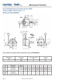
Direction of rotation<br />
Correlation between direction of rotation (shaft view) control and direction of flow.<br />
PUMP FLOW DIRECTION<br />
SHAFT<br />
ROTATION<br />
LEFT<br />
(counterclockwise)<br />
RIGHT<br />
(clockwise)<br />
Energized<br />
Solenoid<br />
Pressure<br />
Port<br />
1 B<br />
2 A<br />
1 A<br />
2 B<br />
Pag. 12 HT 16 / M / 604 / 1111 / E
Closed Circuit<br />
Variable Displacement<br />
AUTOMOTIVE CONTROL <strong>with</strong> HYDRAULIC INCHING<br />
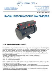
Installation Drawing<br />
Axial Piston Pump TPV 5000<br />
<strong>AM2</strong>/<strong>AM4</strong>-II<br />
METRIC Version<br />
A – B: Pressure Ports – SAE Flange 6000 - 3/4"<br />
f: SAE flanges fixing holes - M10 depth 15 mm.<br />
D1 – D2: Drain Port – 1/2" G<br />
S: Suction – 1" G<br />
Va: Boost Pump Pressure Relief Valve<br />
V1 – V2: Main Port Pressure Relief Valve<br />
Bp: By-pass Valve<br />
Sl: Stroke Limiter<br />
Zm: Mechanical Zero adjustment screw<br />
p: Boost Pressure gauge Port – 1/8" G<br />
p1: a – b Pilot Line Gauge Port – 1/4" G<br />
Pi: <strong>Inching</strong> Inlet Line – 1/8" G<br />
Lp: Power Limiter Adjusting Screw<br />
Pm: Machine Start-Up Adjusting Screw<br />
P1r: Minimum Pressure Adjusting Screw<br />
p 2: Pilot Pressure Gauge Port – ¼ “G<br />
p A-B: A-B Gauge Port (A-B) – ¼“ G<br />
SAE Version<br />
A – B: Pressure Ports – SAE Flange 6000 - 3/4"<br />
f: SAE flanges fixing holes - 3/8"-16 UNC 2B depth 15 mm.<br />
D1 – D2: Drain Port – 3/4"-16 UNF-2B<br />
S: Suction – 1" 5/16-12 UNF-2B<br />
Va: Boost Pump Pressure Relief Valve<br />
V1 – V2: Main Port Pressure Relief Valve<br />
Bp: By-pass Valve<br />
Sl: Stroke Limiter<br />
Zm: Mechanical Zero adjustment screw<br />
p: Boost Pressure gauge Port – 3/8"-24 UNF-2B<br />
p1: a – b Pilot Line Gauge Port– 7/16"-20 UNF-2B<br />
Pi: <strong>Inching</strong> Inlet Line- 3/8"-24 UNF-2B<br />
Lp: Power Limiter Adjusting Screw<br />
Pm: Machine Start-Up Adjusting Screw<br />
P1r: Minimum Pressure Adjusting Screw<br />
p 2: Pilot Pressure Gauge Port – 7/16"-20 UNF-2B<br />
p A-B: A-B Gauge Port (A-B) – 7/16"-20 UNF-2B<br />
HT 16 / M / 604 / 1111 / E Pag. 13