Systems for Fiber Optic Applications - PZT & Piezo Actuators: Sub ...
Systems for Fiber Optic Applications - PZT & Piezo Actuators: Sub ...
Systems for Fiber Optic Applications - PZT & Piezo Actuators: Sub ...

Create successful ePaper yourself
Turn your PDF publications into a flip-book with our unique Google optimized e-Paper software.
<strong>Piezo</strong> • Nano • Positioning<br />
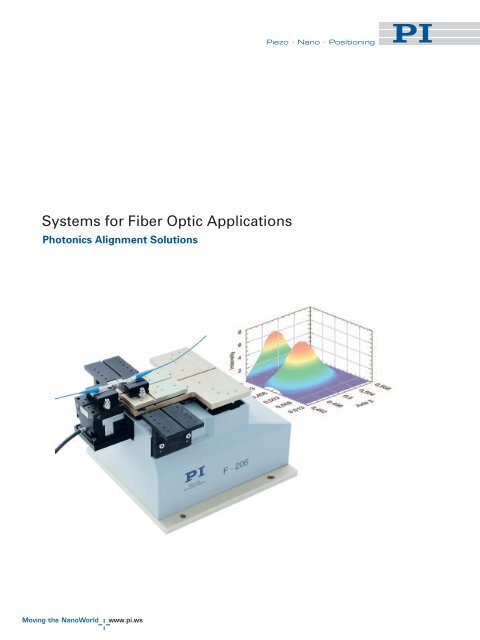
<strong>Systems</strong> <strong>for</strong> <strong>Fiber</strong> <strong>Optic</strong> <strong>Applications</strong><br />
Photonics Alignment Solutions
<strong>Piezo</strong> • Nano • Positioning<br />
Contents<br />
Solutions <strong>for</strong> <strong>Fiber</strong> <strong>Optic</strong>s <strong>Applications</strong><br />
Contents . . . . . . . . . . . . . . . . . . . . . . . . . . . . . . . . . . . . . . . . . . . . . . . . . . . . . . . . . . . . . . . 2<br />
Moving the NanoWorld - The PI Company<br />
Precision Positioning <strong>for</strong> Science and Industry . . . . . . . . . . . . . . . . . . . . . . . . . . . . . . . . 3<br />
Thinking in <strong>Systems</strong><br />
All from One Hand . . . . . . . . . . . . . . . . . . . . . . . . . . . . . . . . . . . . . . . . . . . . . . . . . . . . . . . 4<br />
Software from PI<br />
Operating Positioning <strong>Systems</strong> Effectively & Conveniently . . . . . . . . . . . . . . . . . . . . . 5<br />
Programming<br />
Quick Integration in LabVIEW & Other Programming Languages . . . . . . . . . . . . . . . . 6<br />
PIMikroMove<br />
Host Software <strong>for</strong> Motion <strong>Systems</strong> . . . . . . . . . . . . . . . . . . . . . . . . . . . . . . . . . . . . . . . . . 8<br />
Selection Guide Photonics Alignment Solutions . . . . . . . . . . . . . . . . . . . . . . . . . . . . . . 9<br />
6D-Alignment <strong>Systems</strong><br />
F-206 6-DoF HexAlign Precision Alignment System . . . . . . . . . . . . . . . . . . . . . . . . . 10<br />
Options & Accessories <strong>for</strong> Hexapods . . . . . . . . . . . . . . . . . . . . . . . . . . . . . . . . . . . . . . . 12<br />
Photometer / Pattern Recognition<br />
F-361 High-Speed <strong>Optic</strong>al Power Meter . . . . . . . . . . . . . . . . . . . . . . . . . . . . . . . . . . . . . 14<br />
F-311 PIMotion&Vision - Integration of Vision System<br />
and Micro/Nanopositioning . . . . . . . . . . . . . . . . . . . . . . . . . . . . . . . . . . . . . . . . . . . . . . 16<br />
High-Speed Alignment <strong>Systems</strong><br />
P-611 NanoCube ® XYZ Rapid Photonics NanoAlignment Add-on System . . . . . . . . 18<br />
F-130, F-131 Compact XYZ Hybrid Motorized/<strong>Piezo</strong>electric<br />
Photonics Alignment <strong>Systems</strong> . . . . . . . . . . . . . . . . . . . . . . . . . . . . . . . . . . . . . . . . . . . . 20<br />
Accessories<br />
F-603 <strong>Fiber</strong>, Objective and Waveguide Holders . . . . . . . . . . . . . . . . . . . . . . . . . . . . . . . 22<br />
2
<strong>Piezo</strong> • Nano • Positioning<br />
Moving the Nanoworld<br />
NanoAutomation ® : Precision Positioning <strong>for</strong> Science and Industry<br />
PI headquarters in Karlsruhe<br />
Future Technology Solutions<br />
Today PI delivers micro- and<br />
nanopositioning solutions <strong>for</strong> all<br />
important high-tech markets:<br />
Semiconductor Technology<br />
<strong>Optic</strong>al Metrology, Microscopy<br />
Biotechnology and Medical Devices<br />
Precision Automation and Handling<br />
Precision Machining<br />
Data Storage<br />
Photonics, <strong>Fiber</strong> <strong>Optic</strong>s, Telecom<br />
Nano Technology<br />
Microsystems Technology<br />
Aerospace Engineering<br />
Astronomy<br />
PI is market and technological<br />
leader <strong>for</strong> precision positioning<br />
systems with accuracies well<br />
under one nanometer. Nanometer-range<br />
motion control is<br />
the key to worlds where millions<br />
of transistors fit on one<br />
square millimeter, where molecules<br />
are manipulated, where<br />
thousands of “virtual slices”<br />
are made in the observation of<br />
living cells, or where optical<br />
fiber bundles no larger than a<br />
human hair are aligned in six<br />
degrees of freedom.<br />
Worlds We Call NanoWorlds<br />
Continuous innovation and<br />
reinvestment of profits over<br />
the decades has allowed PI to<br />
attain its present market<br />
status. This status is also based<br />
on long-term customer relationships<br />
and on the freedom<br />
to trans<strong>for</strong>m ideas into reality.<br />
semiconductor manufacturing<br />
or biotechnology would become<br />
dependent on progress in<br />
nanopositioning. Today, not<br />
even the precision machining<br />
industry can do without<br />
nanometer-level positioning<br />
systems.<br />
Key Technologies In-House<br />
PI follows a vertical integration<br />
strategy designed to develop<br />
and maintain all key technologies<br />
in-house. We supervise<br />
each and every step from<br />
design to delivery in the<br />
following areas: software,<br />
precision mechanics, digital<br />
and analog control electronics,<br />
sub-nanometer capacitive position<br />
sensors, piezo ceramics<br />
and piezo actuators. This assures<br />
the highest quality and<br />
reduces cost.<br />
PI reception desk:<br />
Our employees look<br />
<strong>for</strong>ward to your visit<br />
Over 30 Years Experience<br />
When PI introduced piezoelectric<br />
nanopositioning technology<br />
more than 30 years ago,<br />
typical customers were research<br />
labs and universities<br />
working on laser cavity tuning,<br />
Fabry-Perot interferometers<br />
and filters. Few <strong>for</strong>esaw that<br />
whole industrial sectors like<br />
3
<strong>Piezo</strong> • Nano • Positioning<br />
Thinking in <strong>Systems</strong><br />
All in One Hand—All from One Hand<br />
Digital controllers include advanced<br />
algorithms to improve<br />
the system per<strong>for</strong>mance: coordinate<br />
trans<strong>for</strong>mation matrices<br />
matched to the mechanical<br />
geometries allow <strong>for</strong> commanding<br />
complex systems in<br />
Cartesian coordinates; filters<br />
support servo-control by suppressing<br />
resonant vibrations;<br />
pre-shaping of control signals<br />
minimizes trajectory deviation<br />
during dynamic scans. All functions<br />
are easily accessible<br />
through fast and modern interfaces<br />
and comprehensive user<br />
software and software drivers.<br />
Flexibility Through Competent<br />
Partners<br />
High quality requires qualified<br />
partners. Over the years PI has<br />
thus qualified a number of<br />
highly specialized suppliers<br />
with whom we now work as<br />
partners—partners whose conception<br />
of quality is every bit as<br />
high as our own.<br />
Drive, sensors, mechanics and control<br />
electronics with software—components<br />
of PI’s positioning systems<br />
To assure that the subassemblies<br />
used satisfy PI's quality requirements,<br />
PI fabricates all<br />
components itself, develops the<br />
ultra-high-resolution sensors<br />
and controllers, and programs<br />
both control algorithms and operating<br />
software. In Lederhose<br />
(Thuringia) at PI Ceramic, piezoelectric<br />
drives are developed,<br />
optimized and manufactured.<br />
With PIC, PI is the only positioning<br />
system manufacturer<br />
worldwide which develops its<br />
own piezoelectric actuators to<br />
meet market requirements. The<br />
resulting flexibility is an important<br />
reason <strong>for</strong> the technological<br />
leadership enjoyed by PI<br />
and its customers.<br />
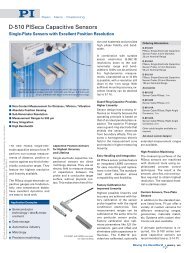
Capacitive Sensors <strong>for</strong><br />
Nanometrology<br />
4<br />
Special sensors can fulfill the<br />
requirements of many applications<br />
<strong>for</strong> dynamics, linearity<br />
and stability better than that<br />
provided by standard strain<br />
gauges. Non-contact capacitive<br />
sensors measure position<br />
without drift and provide linearity<br />
to 0,01% of the measurement<br />
range. The high resolution<br />
of up to 0.0005 % allows<br />
detection and compensation of<br />
the smallest position errors. PI<br />
uses capacitive sensors developed<br />
in-house, making it possible<br />
to adapt the sensor geometries<br />
to the space available.<br />
Placing the sensors as close as<br />
possible to the moving plat<strong>for</strong>m,<br />
PI provides direct metrology<br />
systems—systems in<br />
which motion is detected where<br />
it is used. PI capacitive sensors<br />
are also offered as stand-alone<br />
products <strong>for</strong> nanometrology applications.<br />
Control of Positioning<br />
<strong>Systems</strong><br />
The characteristics of drives<br />
and sensors are made usable<br />
by the drive and control electronics.<br />
PI has designed all electronics<br />
to match the mechanics<br />
optimally. Electronic amplifiers<br />
<strong>for</strong> piezoelectric actuators must<br />
provide low noise and drift.<br />
Fast rise times make possible<br />
sub-millisecond response times<br />
and optimized control algorithms<br />
minimize settling times.<br />
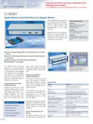
An automation plat<strong>for</strong>m<br />
like the C-880 features<br />
built-in fiber alignment<br />
routines and can<br />
control up to 18 axes.<br />
The systems are easy to<br />
program and are supplied<br />
with a variety of<br />
comprehensive software<br />
drivers and tools<br />
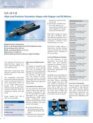
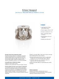
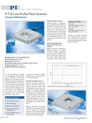
The F-206<br />
HexAlign<br />
alignment system<br />
features 6<br />
degrees of freedom<br />
and<br />
0.1 µm minimal<br />
incremental<br />
motion. An<br />
optional highspeed,<br />
piezodriven<br />
scanning<br />
module with<br />
1 nm resolution<br />
is also available
<strong>Piezo</strong> • Nano • Positioning<br />
PI Software<br />
Operating Positioning <strong>Systems</strong> Effectively & Conveniently<br />
<strong>Piezo</strong> • Nano • Positioning<br />
<strong>Piezo</strong>Walk ® Drives<br />
<strong>Piezo</strong> Nanopositioners<br />
Parallel Kinematic<br />
Nanopositioners<br />
QuickScan VoiceCoil<br />
Scanners<br />
GCS<br />
PILine ® Ultrasonic Drivers<br />
Micropositioners<br />
Parallel Kinematic<br />
<strong>Piezo</strong>Walk ® <strong>Systems</strong><br />
Hexapods<br />
Communication between PI components is based upon a universal command set (GCS – General Command Set). It decouples hardware and software, and is used <strong>for</strong> all drive<br />
principles.<br />
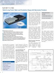
The high quality of positioning<br />
systems is made apparent in<br />
daily operation by PI software.<br />
Starting with simple commissioning,<br />
through convenient<br />
operation with a graphical interface,<br />
to quick and simple integration<br />
in customized programs<br />
with high per<strong>for</strong>mance, PI software<br />
covers all aspects important<br />
to an application.<br />
in syntax and function. Through<br />
the use of the GCS command<br />
set with its convenient functions,<br />
the orientation phase<br />
and application development<br />
process is significantly acceler-<br />
ated. The GCS commands are<br />
available at the controller terminal,<br />
in macros and in the <strong>for</strong>m<br />
of a universal driver set <strong>for</strong> Lab-<br />
VIEW (VIs), Windows dynamic<br />
link libraries (DLL) and Linux<br />
libraries <strong>for</strong> 32- and 64-bit plat<strong>for</strong>ms.<br />
This facilitates the development<br />
of custom macros, as<br />
well as integration with programming<br />
languages like<br />
LabV IEW, C++ or MATLAB.<br />
Universal Command Set<br />
Simplifies Commissioning<br />
and Programming<br />
For uni<strong>for</strong>m operation of nano<br />
and micropositioning systems,<br />
the universal PI General Command<br />
Set (GCS) is used. GCS<br />
operation is independent of the<br />
controller or drive principle<br />
used, so that several positioning<br />
systems can be controlled<br />
together, or new systems can be<br />
introduced with a minimum of<br />
programming ef<strong>for</strong>t. With GCS<br />
the development of custom application<br />
programs is simplified<br />
and less prone to errors, because<br />
the commands <strong>for</strong> all<br />
supported devices are identical<br />
All about software in the internet—a server offers download of manuals and software<br />
CD mirrors<br />
Software Updates Online<br />
PI supports users with free updates,<br />
detailed online help and<br />
well structured manuals which<br />
ease initiation of the inexperienced<br />
but still answer the<br />
detailed questions of the professional.<br />
Supported Operating <strong>Systems</strong><br />
Microsoft Windows Vista<br />
Microsoft Windows XP<br />
Microsoft Windows 2000<br />
Linux<br />
5
<strong>Piezo</strong> • Nano • Positioning<br />
Programming<br />
Quick Integration in LabVIEW<br />
The integration and control of PI<br />
positioning systems under Lab-<br />
VIEW is greatly simplified by the<br />
provision of comprehensive<br />
LabVIEW libraries. The Lab-<br />
VIEW drivers support all controllers<br />
from PI, independent of<br />
the type of connected stage or<br />
controller interface. Thus it is<br />
possible to operate piezo, DC<br />
motor, piezomotor, hybrid and<br />
hexapod controllers with one<br />
driver together in one application.<br />
Quick access to the full functionality<br />
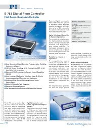
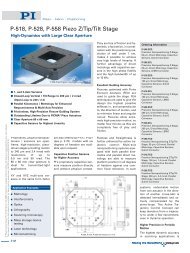
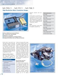
Scan of an optical<br />
device made with<br />
the PI LabVIEW VI<br />
showing the optical<br />
signal intensity distribution.<br />
PI offers a<br />
variety of automatic<br />
alignment routines<br />
designed to determine<br />
the point of<br />
maximum optical<br />
intensity as quickly<br />
as possible<br />
Full Support <strong>for</strong><br />
NI DAQ Boards<br />
The same LabVIEW programs<br />
(virtual instruments, VIs) that<br />
are available <strong>for</strong> PI digital controllers<br />
(e.g. set and read voltages<br />
and positions, velocity,<br />
etc.) can be used in conjunction<br />
with a National Instruments<br />
DAQ (data acquisition) board to<br />
operate positioning systems<br />
based on analog PI controllers.<br />
Furthermore, the patented HyperBit<br />
TM technology is available<br />
under LabVIEW <strong>for</strong> these systems.<br />
HyperBit TM allows attaining<br />
position resolution many<br />
times better than the resolution<br />
of the DAQ board used.<br />
The integrated LabVIEW VIs execute the most complex adjustment routines fast and easily operated, like the automated alignment of<br />
a fiber splitter shown here<br />
6
<strong>Piezo</strong> • Nano • Positioning<br />
Quick and Easy System Setup<br />
For commissioning a positioning<br />
system, the specific Configuration<br />
Setup VI is executed<br />
once. This VI gathers all necessary<br />
system in<strong>for</strong>mation <strong>for</strong><br />
LabVIEW, including:<br />
Communication parameters<br />
Connected controller(s)<br />
Types & configurations of<br />
the connected stages/axes<br />
and per<strong>for</strong>ms all necessary initialisation<br />
steps.<br />
Integrate & Customize Configuration<br />
Setup Vis<br />
The Configuration Setup is implemented<br />
as a sub-VI in customer<br />
applications. With its<br />
connectors, it can be customized<br />
completely to meet the<br />
application requirements. After<br />
it has been run, all command<br />
VIs and high-level routines of<br />
the system can be used. Controller<br />
upgrades or changes<br />
usually require the exchange of<br />
the Configuration Setup VI only.<br />
The open source code of many<br />
VIs offers additional flexibility in<br />
the case of modification needs.<br />
Using Powerful GUI Programs<br />
Directly<br />
Beside the command VIs, highlevel<br />
VIs can be included as sub-<br />
VI in customer applications. A<br />
comprehensive selection of GUI<br />
programs is provided, such as a<br />
terminal application, interface<br />
selection routine, wave generator<br />
samples, 1D and 2D scan<br />
and align functions, joystick<br />
control, etc.<br />
Result of a 2D scan using two motion systems. The configuration setup VI makes<br />
setup of a system very com<strong>for</strong>tably: a special initialization VI is integrated to customize<br />
the software to the application's needs. After it has been run, all command VIs and<br />
high-level routines of the system can be used.<br />
Flexible Integration in Text-Based Programming Languages<br />
The operation of PI positioning<br />
systems from customer applications<br />
running under Microsoft<br />
Windows or Linux is eased with<br />
function libraries and sample<br />
code included.<br />
Maximum Flexibility<br />
The drivers which are provided<br />
support all current programming<br />
languages (see inset) and<br />
all positioning systems from PI.<br />
Since the drivers are based on<br />
the uni<strong>for</strong>m PI GCS command<br />
set (see p. A-11), GCS functionality<br />
can be included directly in<br />
external programs. In addition<br />
to direct GCS commands, the<br />
driver sets also make more<br />
complex functionalities—with<br />
their own graphical interfaces—<br />
available to external programs.<br />
With just one function call by<br />
the customer applications, it is<br />
thus possible, <strong>for</strong> example to<br />
show a graphical user interface<br />
of the Wave Editor or Profile<br />
Generator that handles all user<br />
inputs.<br />
Languages Supported by PI<br />
MATLAB<br />
Visual Basic, Delphi<br />
C, C++, Python<br />
µManager<br />
Epics<br />
MetaMorph<br />
LabVIEW<br />
All programming languages that<br />
support loading of DLLs<br />
A PI positioning system is initialized with C++ and with Matlab using DLL calls<br />
7
<strong>Piezo</strong> • Nano • Positioning<br />
PIMikroMove Software<br />
Simple Operation of Positioning <strong>Systems</strong><br />
The actual position of a multi-axis system can be visualized in addition to the display of<br />
single-axis motion. Shown here is a tilt motion of an F-206 Hexapod. Both the reference<br />
position and the actual position are indicated<br />
Operation of PI Motor, <strong>Piezo</strong>, <strong>Piezo</strong>motor, Hexapod & Hybrid<br />
Controllers<br />
1D/2D Scan and AutoFind<br />
Profile Generator, Joystick Control etc.<br />
Macros <strong>for</strong> Recurring Tasks and Automation<br />
Optimizing all Servo Parameters<br />
can be saved as stage profiles<br />
and then activated as needed in<br />
custom-programmed applications.<br />
Macros Ease Recurring Tasks<br />
PIMikroMove considerably<br />
simplifies the creation of<br />
macros <strong>for</strong> recurring tasks. Execution<br />
of a macro, consisting of<br />
a previously stored list of GCS<br />
commands, can be commanded<br />
over the interface or, if supported<br />
by the controller, run automatically<br />
on power-up, with<br />
or without a host PC connected.<br />
Controllers without their own<br />
macro facility, like the C-843,<br />
can be commanded by host<br />
macros which PIMikroMove<br />
edits and stores in the host PC.<br />
Host macro execution can be<br />
triggered with digital I/O lines or<br />
software commands and support<br />
multiple axes connected to<br />
different controllers.<br />
With the position pad, two or<br />
more independent axes can be<br />
moved by a mouse or joystick<br />
as an XY stage, also in vector<br />
moves.<br />
1D / 2D Scan and AutoFind<br />
Scan 1D / 2D can measure an<br />
input source while moving up<br />
to two axes. Moved axes and<br />
input source need not be assigned<br />
to the same controller.<br />
The input source to be measured<br />
can be an analog input, an<br />
axis position or a raw position<br />
sensor value. The measured<br />
data is visualized and can be<br />
saved to a file on the host PC.<br />
AutoFind tries to find the maximum<br />
of an intensity signal by<br />
modifying the position of two<br />
axes.<br />
FFT, Profile Generator,<br />
Data Recorder<br />
PIMikroMove also supports<br />
controller-specific features.<br />
Data recorder: record various<br />
motion and system parameters,<br />
run FFT (Fast Fourier Trans<strong>for</strong>mation)<br />
on the data as well<br />
as export it to programs like Microsoft<br />
Excel (CSV <strong>for</strong>mat).<br />
Profile Generator: synchronize<br />
motion of several axes along<br />
multi-order, mathematically defined<br />
curves or customized arbitrary<br />
functions.<br />
PI positioning systems can be<br />
controlled with PIMikroMove TM<br />
in a clear and simple manner;<br />
all connected controllers and<br />
axes are accessed via the same<br />
graphical interface.<br />
PIMikroMove supports quick<br />
commissioning of controllers<br />
and positioners, comprehensive<br />
system optimization as well as<br />
the programming of macros.<br />
All Axes in One View<br />
With PIMikroMove all axes<br />
connected can be controlled<br />
from one program instance.<br />
This, independent of which PI<br />
controller is connected to which<br />
axis and which interface (TCP/IP,<br />
USB, RS-232, GPIB, PCI). For ex-<br />
8<br />
ample, it is possible to have two<br />
axes in an XY<br />
application connected to two<br />
different controllers, but still<br />
command them with PIMikro-<br />
Move from the same window.<br />
Optimal System Behavior<br />
PIMikroMove also allows the<br />
user to optimize the system<br />
behavior through convenient<br />
servo tuning. This possibility is<br />
especially helpful if the mechanical<br />
properties of a system<br />
are changed, <strong>for</strong> example by applying<br />
a different load. The system<br />
response and stability can<br />
then be optimized with the convenient<br />
parameter tuning tool.<br />
For recurring tasks, different<br />
sets of optimized parameters<br />
Results of a 2D scan per<strong>for</strong>med with an F-206 HexAlign TM micropositioning system
<strong>Piezo</strong> • Nano • Positioning<br />
Selection Guide<br />
Photonics Alignment Solutions<br />
Hexapod 6D-Alignment <strong>Systems</strong>, Photometer Options<br />
Models* Description Axes Page<br />
F-206 HexAlign 6-axis precision alignment system / manipulator (Hexapod) 6 + 2 10<br />
Options & Accessories <strong>for</strong> Hexapods 12<br />
F-361 Absolute-measuring integrating sphere optical power meter – 14<br />
Software Solution <strong>for</strong> Intelligent Automation Tasks<br />
Models* Description Axes Page<br />
F-311 PIMotion&Vision System <strong>for</strong> micro-/nanopositioning unlimited 16<br />
Compact Motorized/<strong>Piezo</strong>electric Hybrid Photonics Alignment Solutions<br />
Models* Description Axes Page<br />
F-130, Compact XYZ hybrid-fiber alignment system 3/3 (Hybrid) 20<br />
F-131 with motor drives and piezo actuators<br />
P-611 NanoCube ® , fast XYZ nanopositioning system, 100 µm Z-travel 3 18<br />
Accessories<br />
Models* Description Axes Page<br />
F-603 <strong>Fiber</strong>, objective and waveguide holders – 22<br />
* Ask about custom designs. Page references in the datasheets refer to the main catalog (<strong>Piezo</strong> Nano Positioning. Inspirations 2009)<br />
Find more parallel-kinematics systems, Hexapods and multi-axis automation controllers in the main catalog and on www.pi.ws.<br />
M-824 Vacuum compatible<br />
compact Hexapod<br />
M-840 HexaLight Hexapod,<br />
fast, medium load capacity<br />
M-850 High-load Hexapod,<br />
optional photometer<br />
M-810 Miniature Hexapod M-833 Tripod: X, Z, θ Y<br />
goniometer<br />
C-880 Automation plat<strong>for</strong>m<br />
<strong>for</strong> plug-in cards<br />
9
<strong>Piezo</strong> • Nano • Positioning<br />
F-206.S HexAlign 6 Axis-Hexapod<br />
Parallel-Kinematics Precision Alignment System / Manipulator, with Controller<br />
© Physik Instrumente (PI) GmbH & Co. KG 2008. <strong>Sub</strong>ject to change without notice. All data are superseded by any new release.<br />
The newest release <strong>for</strong> data sheets is available <strong>for</strong> download at www.pi.ws. R1 09/05.0<br />
Application Examples<br />
Micromachining<br />
Photonics packaging<br />
<strong>Fiber</strong> alignment<br />
Semiconductor handling /<br />
test systems<br />
Micromanipulation (life<br />
science)<br />
<strong>Optic</strong>al device testing<br />
Collimator and fiber<br />
bundle alignment<br />
MEMS<br />
positioning/alignment<br />
The F-206.S Hexapod comes with a<br />
digital 6D controller and comprehensive software<br />
Parallel Kinematics with 6 Degrees of Freedom<br />
0.033 µm Actuator Resolution<br />
Repeatability 0.3 µm in Space<br />
No Moving Cables <strong>for</strong> Improved Reliability, Reduced Friction<br />
Better Dynamics, More Compact than Serial Kinematics <strong>Systems</strong><br />
For Scanning and Alignment<br />
Cartesian Coordinate Control with Virtualized Pivot Point<br />
Powerful Digital Controller with Open Source LabVIEW<br />
Drivers, DLL Libraries...<br />
Integrated <strong>Fiber</strong> Alignment Routines<br />
10<br />
The F-206.S HexAlign TM Hexapod<br />
is a highly accurate micropositioning<br />
system <strong>for</strong> complex<br />
multi-axis alignment tasks. It is<br />
based on PI’s long experience<br />
with ultra-high-resolution, parallel<br />
kinematics stages. Unlike<br />
hexapods with variable-length<br />
struts (“legs”) the F-206 features<br />
constant-length struts and<br />
friction-free flexure guides. This<br />
gives the F-206 even higher precision<br />
than other hexapod designs.<br />
Compact, Plug & Play<br />
The F-206.S Hexapod is considerably<br />
smaller and more accurate<br />
than comparable serial<br />
kinematics six-axis systems<br />
(stacks of single-axis units).<br />
The parallel kinematics of the F-<br />
206 is immune to the cumulative<br />
bending and guiding errors<br />
of the various axes which, together<br />
with the inertia and friction<br />
of the moving cables, can<br />
limit accuracy in stacked systems.<br />
In addition, rotations are<br />
not set in hardware, but about a<br />
pivot point freely definable in<br />
software. A high-per<strong>for</strong>mance<br />
controller does all necessary<br />
coordinate trans<strong>for</strong>mation <strong>for</strong><br />
coordinating the six drives. Because<br />
all the actuators are attached<br />
directly to the same<br />
moving plat<strong>for</strong>m, there are<br />
none of the servo-tuning problems<br />
associated with the loading<br />
and inertia differences of<br />
the different axes, as are inherent<br />
in stacked systems.<br />
Virtualized Pivot Point<br />
It is important to have a fixed<br />
pivot point <strong>for</strong> alignment tasks,<br />
especially in photonics packaging.<br />
Because the parallel kinematics<br />
motion of the F-206 is<br />
calculated with complex algorithms<br />
in the digital controller,<br />
it was easy to allow programming<br />
any point in space as center<br />
of rotation. Furthermore, the<br />
cartesian coordinates of any<br />
position and any orientation<br />
can be entered directly and the<br />
specified target will be reached<br />
after travel along a smooth<br />
path.<br />
Six Degrees of Freedom,<br />
No Moving Cables<br />
In the F-206 parallel kinematics<br />
design, all cable terminations<br />
are on the stationary base, eliminating<br />
unpredictable friction<br />
and inertia, improving resolution<br />
and repeatability. Further<br />
advantages of the system are:<br />
No cable guides required<br />
Reduced Size and Inertia<br />
Improved Dynamic and Settling<br />
Behavior<br />
Identical Modular <strong>Actuators</strong><br />
<strong>for</strong> Simplified Servicing<br />
Open Command Set, Simplified<br />
Programming<br />
Ordering In<strong>for</strong>mation<br />
F-206.S0<br />
Hexapod 6-Axis Precision Alignment<br />
System / Manipulator with 6<br />
DOF Hexapod Controller<br />
F-206.SD<br />
Hexapod 6-Axis Precision Alignment<br />
System / Manipulator with 6<br />
DOF Hexapod Controller, Built-in<br />
Display and Keypad<br />
Options and Accessories<br />
F-206.AC8<br />
Upgrade <strong>for</strong> 2 Additional Servo-<br />
Motor Control Channels on F-206<br />
Controller<br />
F-206.MHU<br />
Force-Limiting Mounting Plat<strong>for</strong>m,<br />
(included with F-206.SD)<br />
F-206.NCU<br />
Upgrades: Rapid Nanopositioning<br />
Upgrade <strong>for</strong> F-206.S. Consists of<br />
P-611.3SF NanoCube and E-760<br />
Controller Card<br />
F-206.MC6<br />
6D Interactive Manual Control Pad<br />
F-206.VVU<br />
2-Channel Photometer Card,<br />
(Visual Range)<br />
F-206.iiU<br />
2-Channel Photometer Card<br />
(IR Range)<br />
F-361.10<br />
Absolute-Measuring <strong>Optic</strong>al Power<br />
Meter, 1000-1600 nm Wavelength<br />
Additional Accessories,<br />
see www.pi.ws.<br />
Integration of the F-206 in complex<br />
applications is facilitated<br />
by the system’s open command<br />
set and comprehensive tool libraries.<br />
The controller can be<br />
operated either through a host<br />
PC, or directly through a keyboard<br />
and monitor. It can also<br />
run programs stored in a userfriendly,<br />
fully documented<br />
macro language.<br />
Automatic <strong>Optic</strong>al Alignment<br />
Optional internal and external<br />
photometers are available. Both<br />
types are fully integrated with<br />
the controller hardware and<br />
with routines designed <strong>for</strong> automatic<br />
alignment of collimators,<br />
optical fibers and arrays.<br />
For more in<strong>for</strong>mation on the<br />
photometers see www.pi.ws.
<strong>Piezo</strong> • Nano • Positioning<br />
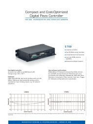
F-206 provides ultra-precise motion in all six degrees of freedom with<br />
rotation about any point in space. The pivot point is set by the user with a<br />
simple software command<br />
F-206.S. Dimensions in mm<br />
Technical Data<br />
Model<br />
Travel range X*<br />
Travel range Y*<br />
Travel range Z*<br />
F-206.S0 / F-206.SD<br />
-8 to +5.7 mm<br />
±5.7 mm<br />
±6.7 mm<br />
Travel range θ X * ±5.7°<br />
Travel range θ Y * ±6.6°<br />
Travel range θ Z * ±5.5°<br />
Actuator resolution<br />
Minimum incremental motion X, Y, Z**<br />
33 nm<br />
0.1 µm (6-axis move!)<br />
Minimum incremental motion θ X , θ Y , θ Z ** 2 µrad (0.4") (6-axis move!)<br />
Bidirectional repeatability X, Y, Z 0.3 µm<br />
Bidirectional repeatability θ X , θ Y , θ Z<br />
Speed X, Y, Z<br />
Maximum load in Z<br />
Mass<br />
Controller<br />
Operating voltage<br />
Software<br />
3.6 µrad<br />
0.01 to 10 mm/s<br />
2 kg (centered on plat<strong>for</strong>m)<br />
5.8 kg<br />
Digital Hexapod controller with optional<br />
photometer card and integrated scan and<br />
align routines<br />
100–240 VAC, 50/60 Hz<br />
LabVIEW drivers, software <strong>for</strong> alignment<br />
of arrays, DLL libraries, scan<br />
and align software, terminal software<br />
*Travel ranges in the coordinate directions (X, Y, Z θ X , θ Y , θ Z ) are interdependent. The data given shows<br />
maximum travel range of the axis in question (i. e. its travel when all other axes are at their zero<br />
positions). If this is not the case, the available travel may be less.<br />
**Six-axis move. No moving cables (unlike serial-kinematic stacked systems) to introduce bending<br />
<strong>for</strong>ces, torque and friction which degrade positioning accuracy.<br />
Interferometer test of an F-206.S system shows the excellent repeatability<br />
of small steps, here 0.5 µm spaced at 100 ms<br />
11
<strong>Piezo</strong> • Nano • Positioning<br />
Hexapod Options & Accessories<br />
Photometer card<br />
The F-206.MC6 manual control pad facilitates system setup and<br />
testing procedures. It permits independent motion in all degrees<br />
of freedom with programmable step size<br />
© Physik Instrumente (PI) GmbH & Co. KG 2009. <strong>Sub</strong>ject to change without notice. All data are superseded by any new release.<br />
The newest release <strong>for</strong> data sheets is available <strong>for</strong> download at www.pi.ws. 09/05.0<br />
<strong>Optic</strong>al Metrology Boards<br />
The controllers <strong>for</strong> the F-206, M-<br />
840 and M-850 Hexapod<br />
systems can be equipped/ retrofitted<br />
with the following photometer<br />
cards: F-206.VVU<br />
(2-channel, visual) and F-206.iiU<br />
(2-channel, IR).<br />
F-206.MC6 6D Interactive Control<br />
Pad Upgrade<br />
The F-206.MC6 manual control<br />
pad facilitates system setup and<br />
Technical Data<br />
<strong>Optic</strong>al power range<br />
Analog input voltage range<br />
A/D resolution<br />
Sample rate<br />
Bandwidth<br />
Max. sensitivity at:<br />
Options <strong>for</strong> F-206 systems<br />
Force-Limiting Plat<strong>for</strong>m<br />
In some applications it may be<br />
useful to limit the <strong>for</strong>ces on or<br />
from the F-206 plat<strong>for</strong>m to protect<br />
the mechanics or components<br />
mounted on the F-206<br />
from damage:<br />
F-206.MHU<br />
F-206.MHU is a magnetic kinematically<br />
clamped, add-on plat-<br />
testing procedures. It consists<br />
of a board that plugs into the<br />
Hexapod controller and a control<br />
pad with six digital “potentiometer”<br />
knobs (one <strong>for</strong> each<br />
degree of freedom).<br />
The manual pad works seamlessly<br />
with the Hexapod software,<br />
and allows programmable<br />
step sizes of 0.1 µm to<br />
500 µm (linear) and 0.001 to<br />
0.5deg (angular) per step. External<br />
positioning commands (via<br />
the computer interface) can be<br />
intermixed with manual positioning<br />
input without loss of the<br />
true position, because both inputs<br />
operate on the same position<br />
registers of the Hexapod<br />
controller. The control pad<br />
comes with a 3 m cable. A 3 m<br />
extension cable is available as<br />
part number C-815.MC6.<br />
F-206.iiU, F-206.VVU <strong>Optic</strong>al Metrology Boards<br />
5 nW – 10 mW<br />
0 – 10 V<br />
16-bit<br />
10 kHz<br />
300 Hz (optical input), 10 kHz (electrical input)<br />
880 nm (visible, F-206.VVU); 1550 nm (IR range, F-206.iiU)<br />
40% sensitivity at: 480 / 1040 nm (visible, F-206.VVU); 850 / 1680 nm (IR range, F-206.iiU)<br />
<strong>for</strong>m which consists of two<br />
parts. The upper part, also available<br />
separately under order<br />
number F-206.TMU, releases itself<br />
automatically when a certain<br />
<strong>for</strong>ce or torque is exceeded.<br />
With multiple F-206.TMUs,<br />
complete setups mounted on<br />
different top plates can be interchanged<br />
quickly and easily. F-<br />
206.MHU is included as standard<br />
with F-206.Sx.<br />
More Options see F-311 PIMotion&Vision<br />
System, F-361<br />
<strong>Optic</strong>al Power Meter and F-603<br />
<strong>Fiber</strong>, Objective and Waveguide<br />
Holders.<br />
The F-206 HexAlign 6D alignment system<br />
combines high resolution and high accuracy<br />
with rapid response, and allows fully automatic<br />
alignment of fiber optic components. The optional<br />
NanoCube ® module (front left) achieves nanometer<br />
resolution and, with its rapid-response piezo drive, can<br />
scan and characterize the entire cross-section of an optical<br />
component in a few seconds (see P-611, p. 2-52)<br />
12
<strong>Piezo</strong> • Nano • Positioning<br />
F-206.NCU Rapid NanoAlign<br />
Upgrade<br />
For applications where alignment<br />
with nanometer-range<br />
resolution is required, or where<br />
rapid mapping of the entire<br />
cross-section of a component in<br />
as short a time as possible<br />
is desired, the F-206.NCU<br />
Rapid NanoAlign upgrade is<br />
recommended. It consists of the<br />
F-206.MHU Magnetic kinematically<br />
clamped <strong>for</strong>ce limiting plat<strong>for</strong>m<br />
P-611.3SF XYZ piezo-drive<br />
NanoCube ® (see p. 2-52) and the<br />
E-760 controller board (see p. 2-<br />
138), which is installed in the F-<br />
206 controller.<br />
Ordering In<strong>for</strong>mation<br />
F-206.MC6<br />
6D Interactive Manual Control Pad<br />
C-815.MC6<br />
3 m Extension Cable <strong>for</strong> Manual<br />
Control Pad<br />
F-206.iiU<br />
2-Channel Photometer Card<br />
(IR Range)<br />
F-206.VVU<br />
2-Channel Photometer Card<br />
(Visual Range)<br />
F-206.AC8<br />
Upgrade <strong>for</strong> 2 Additional<br />
Servo-Motor Control Channels<br />
on Hexapod Controller<br />
F-311<br />
PIMotion&Vision Imaging Processing<br />
<strong>for</strong> Intelligent Automation<br />
F-361.10<br />
Absolute-Measuring <strong>Optic</strong>al Power<br />
Meter, 1000-1600 nm Wavelength<br />
Upgrades / Options <strong>for</strong> F-206 <strong>Systems</strong><br />
F-206.MHU<br />
Force-Limiting Mounting Plat<strong>for</strong>m<br />
(included with F-206.Sx)<br />
F-206.TMU<br />
Additional Mounting Plat<strong>for</strong>m, <strong>for</strong><br />
rapid exchange of different setups<br />
F-206.NCU<br />
Rapid Nanopositioning Upgrade<br />
<strong>for</strong> F-206. Consists of P-611.3SF<br />
NanoCube ® and E-760 Controller<br />
Card<br />
M-500.206<br />
Adapter Plate <strong>for</strong> Mounting F-206 on<br />
M-511, M-521 and M-531 Translation<br />
Stages<br />
Ask about custom designs!<br />
F-206.NCU Rapid NanoAlign Upgrade consists of the P-611 NanoCube ®<br />
piezo nanopositioner and the E-760 controller card<br />
13
<strong>Piezo</strong> • Nano • Positioning<br />
F-361 <strong>Optic</strong>al Power Meter<br />
High-Speed Integrating Sphere <strong>Optic</strong>al Power Meter<br />
F-361 comes with an RS-232 interface<br />
board <strong>for</strong> the PI motion<br />
controllers, interface cables,<br />
power supply, installation and<br />
operation manual and software.<br />
Ordering In<strong>for</strong>mation<br />
F-361.10<br />
High-Speed <strong>Optic</strong>al Power Meter,<br />
NIST Traceable, 1000-1600 nm<br />
Wavelength<br />
Compatible to<br />
F-361 integrating sphere<br />
and optical power meter.<br />
PI Parallel Kinematics Hexapod<br />
<strong>Systems</strong> like F-206,<br />
M-824, M-840, M-850 or<br />
M-810<br />
C-880 Multi-Axis Automation<br />
Plat<strong>for</strong>m<br />
© Physik Instrumente (PI) GmbH & Co. KG 2008. <strong>Sub</strong>ject to change without notice. All data are superseded by any new release.<br />
The newest release <strong>for</strong> data sheets is available <strong>for</strong> download at www.pi.ws. R1 09/05.0<br />
Ultra Fast: 5 ksamples/s<br />
Power Range 1 nW to 100 mW<br />
Absolute Power Measurement, NIST Traceable<br />
Display <strong>for</strong> Instantaneous and Test Measurements<br />
Spectral Range 1000 nm to 1600 nm<br />
Compatible to PI Hexapod <strong>Systems</strong><br />
Compatible to PI C-880 Multi-Axis Alignment<br />
Absolute Power Measurement,<br />
NIST Traceable<br />
F-361 is a very sensitive, absolute<br />
measuring power meter.<br />
All incoming light is detected<br />
by three InGaAs detectors in its<br />
integrating sphere. All F-361 are<br />
calibrated and NIST traceable.<br />
10 7 Power Range<br />
The F-361 is extremely sensitive,<br />
the minimum signal resolution<br />
already starts at 1 nW. It<br />
covers a range of 8 orders of<br />
magnitude to 100 mW. For<br />
Application Examples<br />
<strong>Fiber</strong> alignment<br />
<strong>Optic</strong>al measurement<br />
Characterization of optical<br />
parts or MEMS<br />
Quality assurance of<br />
optical parts or MEMS<br />
14<br />
higher optical power, an attenuator<br />
can be used.<br />
High Speed<br />
The F-361 provides a high<br />
bandwidth of 5 kHz, a prerequisite<br />
<strong>for</strong> automatic alignment.<br />
Compatibility to PI Alignment<br />
<strong>Systems</strong><br />
PI offers various photonics<br />
alignment systems consisting<br />
of precision mechanics up to<br />
1 nm resolution, advanced motion<br />
controllers, high level software<br />
and open-source alignment<br />
routines.<br />
The F-361 is compatible to all PI<br />
alignment systems such as<br />
Hexapod, C-880 and existing<br />
systems with relative power<br />
meters can be upgraded<br />
(firmware update required). Up<br />
to two F-361 can be used with<br />
the above alignment systems.<br />
Technical Data<br />
Models<br />
Function<br />
Channels 1<br />
Spectral range<br />
Calibration<br />
Power range<br />
Bandwidth<br />
F-361.10<br />
High-speed optical power meter <strong>for</strong><br />
absolute power measurement<br />
1000 nm to 1600 nm<br />
NIST traceable<br />
1 nW to 100 mW<br />
5 kHz<br />
Absolute accuracy 8.5 %<br />
Autoranging time 140 µs<br />
Interface<br />
<strong>Fiber</strong> connector<br />
Detector<br />
Dimensions<br />
Weight<br />
USB, RS-232<br />
FC<br />
3 x InGaAs<br />
99.5 x 88 x 78 mm<br />
865 g
<strong>Piezo</strong> • Nano • Positioning<br />
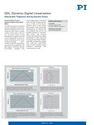
F-361 power meter with F-206 HexAlign 6D precision alignment system<br />
F-361, dimensions in mm<br />
Spectral sensitivity of the InGaAs sensor. The measured optical power is standardized<br />
15
<strong>Piezo</strong> • Nano • Positioning<br />
F-311 PIMotion&Vision<br />
Integration of Vision System and Micro-/Nanopositioning<br />
© Physik Instrumente (PI) GmbH & Co. KG 2008. <strong>Sub</strong>ject to change without notice. All data are superseded by any new release.<br />
The newest release <strong>for</strong> data sheets is available <strong>for</strong> download at www.pi.ws. R1 09/05.0<br />
Vision System <strong>for</strong> Integration with PI Micro- and Nanopositioning<br />
<strong>Systems</strong><br />
Controls Motion Axes with <strong>Sub</strong>-µm or <strong>Sub</strong>-nm<br />
(<strong>Sub</strong>-µrad) Resolution<br />
National Instruments Compatible Vision System<br />
Multi-Channel Vision <strong>for</strong> a Mix of Resolutions and/or 3D<br />
Observation<br />
Powerful LabVIEW VIs<br />
PIMotion&Vision offers an integrated<br />
solution <strong>for</strong> difficult<br />
tasks such as automated positioning<br />
of optics, semi-conductor<br />
wafers, microsystems<br />
technology MEMS fabrication<br />
or alignment and scanning of<br />
samples under a microscope:<br />
Basic functions such as<br />
autofocus, edge and pattern<br />
Application Examples<br />
<strong>Optic</strong>al 6D alignments<br />
Autofocussing<br />
Gap measurements<br />
Pattern recognition in<br />
16<br />
- Semiconductor industry<br />
- Biotechnology<br />
- Life science<br />
- MEMS<br />
Manufacturing/MST<br />
- Photonics<br />
recognition, and gap measurement.<br />
Intelligent automated procedures.<br />
NI Framegrabber<br />
F-311<br />
PIMotion&Vision<br />
software<br />
integrates vision<br />
systems with PI Microand<br />
Nanopositioners.<br />
The hardware <strong>for</strong> the F-311 PI-<br />
Motion&Vision system consists<br />
of a National Instruments<br />
PCI bus framegrabber card.<br />
This fact guarantees a high degree<br />
of compatibility <strong>for</strong> further<br />
system integration. The<br />
framegrabber card supports a<br />
number of camera systems and<br />
is available with one or four<br />
channels.<br />
Software Interface to Microand<br />
Nanopositioners<br />
PIMotion&Vision offers a<br />
large number of LabVIEW drivers<br />
<strong>for</strong> continuous monitoring<br />
and processing of the image in<strong>for</strong>mation,<br />
including standard<br />
procedures <strong>for</strong> gap measurement,<br />
autofocus, aligning edges<br />
all the way to complex alignment<br />
routines in six degrees of<br />
freedom with an unlimited<br />
number of axes of motion,<br />
switching functions and read-in<br />
of analog signals (e.g. photometer<br />
signals <strong>for</strong> optical fiber<br />
alignment).<br />
Motion is commanded using<br />
the PI General Command Set,<br />
which is supported by all PI<br />
multi-axis micropositioning and<br />
nanopositioning controllers.<br />
The basic version contains all<br />
the drivers provided by PI; the<br />
Pro Version includes the full<br />
IMAQ development environment<br />
from National Instruments,<br />
making possible an<br />
even wider range of system integration<br />
and function development.<br />
Notes<br />
Optimal per<strong>for</strong>mance in transmitted-light<br />
applications can be<br />
obtained with the F-311.L10 illu-<br />
Ordering In<strong>for</strong>mation<br />
F-311.V01<br />
PIMotion&Vision Basic Module,<br />
1CH<br />
F-311.V04<br />
PIMotion&Vision Basic Module,<br />
4CH<br />
F-311.V11<br />
PIMotion&Vision Pro Module,<br />
1CH<br />
F-311.V14<br />
PIMotion&Vision Pro Module,<br />
4CH<br />
F-311.V1U<br />
PIMotion&Vision Upgrade to<br />
Pro Module<br />
F-311.L10<br />
PIMotion&Vision Illumination<br />
System<br />
mination system, developed by<br />
PI. The light intensity is adjustable<br />
and the use of LEDs assure<br />
long lifetime. The unit can<br />
be powered directly from the PI<br />
controller, a feature which helps<br />
reduce the number of components.<br />
<strong>Optic</strong>al fiber-alignment with F-206 6-axis-alignment system and P-611 NanoCube ®<br />
3D piezo nanopositioning / scanning system. Two cameras allow a 3-dimensional<br />
visual automated coarse alignment.
<strong>Piezo</strong> • Nano • Positioning<br />
Simple setup with a single camera, two<br />
M-111 stages in an XY configuration and<br />
an M-116 rotary plat<strong>for</strong>m (all controlled<br />
from a C-843 PCI card). This sample setup<br />
can be used <strong>for</strong> pattern recognition, as can<br />
be seen in the next graphics.<br />
PIMotion&Vision sample pattern recognition task. The sample program searches<br />
<strong>for</strong> PI logos, counts and aligns them. The logos are 1 x 0.5 mm in size.<br />
Example of a gap measurement with PIMotion&Vision. The measurement is linear<br />
down to 5 µm, depending on the used camera, and at separations down to 1 µm the<br />
values provided can be used with correction. <strong>Optic</strong>al gap measurement then begins to<br />
be limited by refraction and optical imperfections. The reference measurements were<br />
made with a P-611 NanoCube ® <strong>Piezo</strong>-NanoPositioning system.<br />
17
<strong>Piezo</strong> • Nano • Positioning<br />
P-611.3OF · P-611.3SF NanoCube ®<br />
XYZ Rapid Photonics NanoAlignment Add-on System<br />
Automatic Alignment<br />
NanoCubes ® can be operated<br />
with the E-664 bench-top controller.<br />
A variety of other rackmount<br />
and bench-top controllers<br />
is also available.<br />
NanoCubes ® can be easily combined<br />
with a number of automated<br />
or manual PI micropositioning<br />
systems, from single<br />
axis stages to 6-degree-offreedom<br />
micromanipulators.<br />
Ordering In<strong>for</strong>mation<br />
P-611.3SF<br />
NanoCube ® XYZ NanoAlignment<br />
Stage, 100 x 100 x 100 µm, Closed-<br />
Loop, <strong>Fiber</strong> Adapter Interface<br />
P-611.3OF<br />
NanoCube ® XYZ NanoAlignment<br />
Stage, 100 x 100 x 100 µm, Open-<br />
Loop, <strong>Fiber</strong> Adapter Interface<br />
F-206.NCU<br />
Rapid Nanopositioning Upgrade<br />
<strong>for</strong> F-206. Consist of P-611.3SF<br />
NanoCube ® and E-760 Controller<br />
Card<br />
Working Principle / Lifetime<br />
Ask about custom designs!<br />
© Physik Instrumente (PI) GmbH & Co. KG 2008. <strong>Sub</strong>ject to change without notice. All data are superseded by any new release.<br />
The newest release <strong>for</strong> data sheets is available <strong>for</strong> download at www.pi.ws. R1 09/05.0<br />
P-611 NanoCube ® , XYZ Compact NanoAlignment System, 100 x 100 x 100 µm<br />
travel range, 1 nm resolution, shown with optional F-603.22 ferrule holder.<br />
Ideal <strong>for</strong> <strong>Fiber</strong> Alignment and Photonics Packaging <strong>Applications</strong><br />
100 x 100 x 100 µm Travel Range, Ultra-Compact Package!<br />
1 nm Resolution<br />
Closed- and Open-Loop Versions<br />
Precision Trajectory Control w/ Frictionless Flexures<br />
Fast Scanning and Settling<br />
Large Variety of Controllers<br />
Application Examples<br />
Photonics packaging<br />
<strong>Optic</strong>al device testing<br />
MEMS positioning/<br />
alignment<br />
<strong>Fiber</strong> alignment<br />
Micromachining<br />
Micromanipulation<br />
(life sciences)<br />
Semiconductor test<br />
systems<br />
The P-611.3OF and P-611.3SF<br />
NanoCube ® NanoAlignment<br />
systems are based on PI’s vast<br />
experience with ultra-high precision<br />
piezo scanning systems<br />
and photonics packaging applications.<br />
They combine a 100 x<br />
100 x 100 µm XYZ positioning<br />
and scanning range with a zero<br />
stiction/friction wire-EDM-cut<br />
guiding system in an extremely<br />
compact package. NanoCube ®<br />
systems provide motion with<br />
nanometer-scale resolution and<br />
settling times of only a few milliseconds.<br />
Open- & Closed-Loop Models<br />
Open- and closed-loop versions<br />
are offered to suit your application.<br />
Several fiber, waveguide<br />
and optics adapters are available<br />
<strong>for</strong> mounting on the<br />
NanoCube ® (e. g. model<br />
F-603.60)<br />
NanoCubes ® are also available<br />
in a slightly different package<br />
without the fiber adapter interface,<br />
see page 2-52.<br />
P-611 nanopositioners are<br />
equipped with the award-winning<br />
PICMA ® long-life piezoelectric<br />
drives integrated into a<br />
sophisticated flexure guiding<br />
system. The <strong>for</strong>ce exerted by<br />
the piezo drive pushes a multiflexure<br />
parallelogram via an integrated<br />
motion amplifier. The<br />
wire-EDM-cut flexures are FEA<br />
modeled (finite element analysis)<br />
<strong>for</strong> zero stiction and friction,<br />
ultra-high resolution and exceptional<br />
guiding precision. All<br />
components are frictionless<br />
and maintenance-free.<br />
P-611.3OF, P-611.3SF dimensions (in mm)<br />
18
<strong>Piezo</strong> • Nano • Positioning<br />
Combination of NanoCube ® and<br />
F-206 Six-Axis Parallel-Kinematics MicroMotion-Robot<br />
Technical Data<br />
Model P-611.3SF P-611.3OF Units Tolerance<br />
Active axes X, Y, Z X, Y, Z<br />
Motion and positioning<br />
Integrated sensor<br />
SGS<br />
Open-loop travel, -20 to +120 V 120 / axis 120 / axis µm min. (+20 %/0 %)<br />
Closed-loop travel 100 / axis – µm<br />
Open-loop resolution 0.2 0.2 nm typ.<br />
Closed-loop resolution 1 – nm typ.<br />
Linearity 0.1 – % typ.<br />
Repeatability
<strong>Piezo</strong> • Nano • Positioning<br />
F-130 · F-131 Compact XYZ Photonics Alignment System<br />
DC/<strong>Piezo</strong> Drive System <strong>for</strong> Nanometer Precision<br />
Ordering In<strong>for</strong>mation<br />
F-130.3SD<br />
XYZ Alignment System, 5 mm /<br />
100 µm, DC Motor/Encoder,<br />
C/L <strong>Piezo</strong><br />
F-130.3SS<br />
XYZ Alignment System, 5 mm /<br />
100 µm, Stepper Motor, C/L <strong>Piezo</strong><br />
F-130.3OD<br />
XYZ Alignment System 5 mm /<br />
100 µm, DC Motor/Encoder,<br />
O/L <strong>Piezo</strong><br />
© Physik Instrumente (PI) GmbH & Co. KG 2008. <strong>Sub</strong>ject to change without notice. All data are superseded by any new release.<br />
The newest release <strong>for</strong> data sheets is available <strong>for</strong> download at www.pi.ws. R1 09/05.0<br />
Up to 15 mm Travel<br />
1 nm Resolution<br />
Closed-Loop <strong>Piezo</strong> Drives Available<br />
Stepper- & DC-Motor Drives<br />
F-130 are compact computercontrollable<br />
XYZ alignment and<br />
positioning systems combining<br />
the advantages of ultra-highresolution<br />
piezo drives with the<br />
long travel range of motorized<br />
stages.<br />
They are based on the M-110/<br />
M-111 micropositioning stages<br />
(see page 4-22) and the P-611<br />
Application Examples<br />
Photonics packaging<br />
<strong>Optic</strong>al device testing<br />
MEMS positioning/<br />
alignment<br />
<strong>Fiber</strong> alignment<br />
Micromachining<br />
Micromanipulation<br />
(life sciences)<br />
Semiconductor test<br />
systems<br />
F-130.3SD XYZ Alignment System,<br />
1 nm resolution, with optional F-603.22 ferrule holder<br />
rapid piezo NanoAlignment<br />
units (see page 2-20).<br />
The F-130/F-131 is available in 8<br />
different versions, with stepperand<br />
DC-motor coarse drives,<br />
and open- and closed-loop<br />
piezoelectric fine drives. (see<br />
Ordering In<strong>for</strong>mation).<br />
The motor drives provide better<br />
than 0.05 µm resolution over a<br />
travel range of 5 and<br />
15 mm. The piezo fine drives feature<br />
a 100 µm travel range in<br />
X, Y and Z, with zero-stiction,<br />
zero-friction flexure guiding<br />
systems and 1 nm resolution.<br />
Several fiber, waveguide and<br />
optics adapters are available<br />
from PI (e. g. model F-603.60,<br />
see “<strong>Fiber</strong>, Objective and Waveguide<br />
Holders”).<br />
The C-880 multi-axis automation<br />
plat<strong>for</strong>m (see page 4-124) is<br />
recommended as controller.<br />
F-130.3OS<br />
XYZ Alignment System, 5 mm /<br />
100 µm, Stepper Motor, O/L <strong>Piezo</strong><br />
F-131.3SD<br />
XYZ Alignment System, 15 mm /<br />
100 µm, DC Motor/Encoder,<br />
C/L <strong>Piezo</strong><br />
F-131.3SS<br />
XYZ Alignment System, 15 mm /<br />
100 µm, Stepper Motor, C/L <strong>Piezo</strong><br />
F-131.3OD<br />
XYZ Alignment System, 15 mm /<br />
100 µm, DC Motor/Encoder,<br />
O/L <strong>Piezo</strong><br />
F-131.3OS<br />
XYZ Alignment System, 15 mm /<br />
100 µm, Stepper Motor, O/L <strong>Piezo</strong><br />
Ask about custom designs!
<strong>Piezo</strong> • Nano • Positioning<br />
The C-880 Multi-axis automation plat<strong>for</strong>m is recommended<br />
as controller <strong>for</strong> the F-130/F-131<br />
F-130.3xx, dimensions (in mm)<br />
Technical Data<br />
Model F-130.3SD F-130.3SS F-130.3OD F-130.3OS F-131.3SD F-131.3SS F-131.3OD F-131.3OS Units<br />
Key features Closed-loop Stepper Closed-loop Stepper Closed-loop Stepper Closed-loop Stepper<br />
DC motors, motors, DC motors, motors, DC motors, motors, DC motors, motors,<br />
closed-loop closed-loop open-loop open-loop closed-loop closed-loop open-loop open-loop<br />
<strong>PZT</strong> drives <strong>PZT</strong> drives <strong>PZT</strong> drives <strong>PZT</strong> drives <strong>PZT</strong> drives <strong>PZT</strong> drives <strong>PZT</strong> drives <strong>PZT</strong> drives<br />
Active axes X,Y, Z X,Y, Z X,Y, Z X,Y, Z X,Y, Z X,Y, Z X,Y, Z X,Y, Z<br />
Motorized 5 5 5 5 15 15 15 15 mm<br />
travel range (XYZ)<br />
<strong>Piezo</strong> travel 100 100 100 100 100 100 100 100 µm<br />
range (XYZ)<br />
Design 0.007 0.006 0.007 0.006 0.007 0.006 0.007 0.006 µm<br />
resolution (motor)<br />
Min. incremental 0.05 0.05 0.05 0.05 0.05 0.05 0.05 0.05 µm<br />
motion (motor)<br />
Closed-loop / open- 2/1 2/1 - / 1 - / 1 2/1 2/1 - / 1 - / 1 nm<br />
loop resolution (<strong>PZT</strong>)<br />
Motorized stage M-110.3DG M-110.32S M-110.3DG M-110.32S M-111.3DG M-111.32S M-111.3DG M-111.32S<br />
<strong>Piezo</strong> drive P-611.3SF P-611.3SF P-611.3OF P-611.3OF P-611.3SF P-611.3SF P-611.3OF P-611.3OF<br />
Material Al / S Al / S Al / S Al / S Al / S Al / S Al / S Al / S<br />
Recommended C-880 - C-880 - C-880 - C-880 -<br />
controller<br />
21
<strong>Piezo</strong> • Nano • Positioning<br />
F-603 Accessories<br />
<strong>Fiber</strong>, Objective and Waveguide Holders<br />
The F-603 series component<br />
holders <strong>for</strong> fiber optic applications<br />
can be combined with the<br />
following micro- and nanopositioning<br />
systems from PI:<br />
Ordering In<strong>for</strong>mation<br />
F-603.11<br />
Microscope Objective Holder<br />
W0.8 x 1 /36“<br />
F-206 6D-Hexapod-Alignment<br />
System<br />
F-603.12<br />
Microscope Objective Holder<br />
M19 x 0.75<br />
© Physik Instrumente (PI) GmbH & Co. KG 2008. <strong>Sub</strong>ject to change without notice. All data are superseded by any new release.<br />
The newest release <strong>for</strong> data sheets is available <strong>for</strong> download at www.pi.ws. R1 09/05.0<br />
Rear (left to right) Microscope Objective Holders: F-603.14, F-603.12 (mounted on<br />
P-611.3SF NanoCube ® NanoAlignment System) F-603.11, F-603.13<br />
Mount on a Variety of PI Alignment <strong>Systems</strong><br />
Precision Machined from High-Strength Aluminum/Brass<br />
F-130 and F-131 Alignment<br />
<strong>Systems</strong><br />
P-611.3OF and P-611.3SF<br />
NanoCube ® NanoAligners<br />
A variety of combinations<br />
of NanoCubes ® with other<br />
micropositioning systems<br />
All adapters are equipped with<br />
a 3-mm-wide tongue that fits in<br />
a slot machined into the plat<strong>for</strong>m<br />
of the positioning system.<br />
M3 capscrews and miniature<br />
cleats supplied with each F-603<br />
adapter are used to fasten these<br />
accessories quickly.<br />
F-603.13<br />
Microscope Objective Holder<br />
M25 x 0.75<br />
F-603.14<br />
Microscope Objective Holder<br />
M26 x 0.75<br />
F-603.20<br />
Vacuum Waveguide Mount<br />
F-603.21<br />
<strong>Fiber</strong> Holder <strong>for</strong> FC-Connector<br />
F-603.22<br />
Ferrule Holder<br />
F-603.60<br />
V-Groove <strong>Fiber</strong> Holder with Magnetic<br />
Clamp<br />
Ask about custom designs!<br />
22
<strong>Piezo</strong> • Nano • Positioning<br />
F-603.21 fiber holder <strong>for</strong> FC-connector, dimensions in mm<br />
F-603.22 ferrule-holder, dimensions in mm<br />
F-603.11 microscope objective holder W0.8 x 1 / 36 ”<br />
F-603.12 microscope objective holder M19 x 0.75<br />
F-603.13 microscope objective holder M25 x 0.75<br />
F-603.14 microscope objective holder M26 x 0.75<br />
dimensions in mm<br />
23
<strong>Piezo</strong> • Nano • Positioning<br />
Headquarters<br />
GERMANY<br />
Request or download the complete<br />
hardbound catalog<br />
“<strong>Piezo</strong> Nano Positioning<br />
Inspirations 2009“<br />
Products and Technologies<br />
Nanopositioning / Scanning Stages<br />
Scanning Microscopy Stages<br />
Steering Mirrors, Mirror Shifters<br />
<strong>Piezo</strong> <strong>Actuators</strong><br />
<strong>Piezo</strong> Motors<br />
<strong>Piezo</strong> Controllers<br />
Motorized Stages & <strong>Actuators</strong><br />
Motor Controllers<br />
Hexapod 6-Axis Alignment <strong>Systems</strong><br />
Fields of <strong>Applications</strong><br />
Biotechnology/Life Sciences<br />
Semiconductor Technology<br />
Data Storage Technology<br />
Nanotechnology<br />
Aeronautics<br />
Astronomy<br />
Adaptive <strong>Optic</strong>s<br />
Metrology/Laser-<strong>Systems</strong><br />
Precision Machining<br />
Call or go to: http://www.pi.ws<br />
Physik Instrumente (PI)<br />
GmbH & Co. KG<br />
Auf der Römerstr. 1<br />
76228 Karlsruhe/Palmbach<br />
Tel: +49 (721) 4846-0<br />
Fax: +49 (721) 4846-100<br />
info@pi.ws · www.pi.ws<br />
<strong>Sub</strong>sidiaries<br />
USA (East) & CANADA<br />
PI (Physik Instrumente) L.P.<br />
16 Albert St.<br />
Auburn, MA 01501<br />
Tel: +1 (508) 832 3456<br />
Fax: +1 (508) 832 0506<br />
info@pi-usa.us<br />
www.pi-usa.us<br />
JAPAN<br />
PI Japan Co., Ltd.<br />
Akebono-cho 2-38-5<br />
Tachikawa-shi<br />
Tokyo 190<br />
Tel: +81 (42) 526 7300<br />
Fax: +81 (42) 526 7301<br />
info@pi-japan.jp<br />
www.pi-japan.jp<br />
CHINA<br />
Physik Instrumente<br />
(PI Shanghai) Co., Ltd.<br />
Building No. 7-301<br />
Longdong Avenue 3000<br />
201203 Shanghai, China<br />
Tel: +86 (21) 687 900 08<br />
Fax: +86 (21) 687 900 98<br />
info@pi-china.cn<br />
www.pi-china.cn<br />
FRANCE<br />
PI France S.A.S.<br />
32 rue Delizy<br />
93694 Pantin Cedex<br />
Tel: +33 (1) 57 14 07 10<br />
Fax: +33 (1) 41 71 18 98<br />
info@pifrance.fr<br />
www.pifrance.fr<br />
PI Ceramic GmbH<br />
Lindenstr.<br />
07589 Lederhose<br />
Tel: +49 (36604) 882-0<br />
Fax: +49 (36604) 882-25<br />
info@piceramic.de<br />
www.piceramic.de<br />
USA (West) & MEXICO<br />
PI (Physik Instrumente) L.P.<br />
5420 Trabuco Rd., Suite 100<br />
Irvine, CA 92620<br />
Tel: +1 (949) 679 9191<br />
Fax: +1 (949) 679 9292<br />
info@pi-usa.us<br />
www.pi-usa.us<br />
PI Japan Co., Ltd.<br />
Hanahara Dai-ni Building, #703<br />
4-11-27 Nishinakajima,<br />
Yodogawa-ku, Osaka-shi<br />
Osaka 532<br />
Tel: +81 (6) 6304 5605<br />
Fax: +81 (6) 6304 5606<br />
info@pi-japan.jp<br />
www.pi-japan.jp<br />
UK & IRELAND<br />
PI (Physik Instrumente) Ltd.<br />
Trent House<br />
University Way,<br />
Cranfield Technology Park,<br />
Cranfield,<br />
Bed<strong>for</strong>d MK43 0AN<br />
Tel: +44 (1234) 756 360<br />
Fax: +44 (1234) 756 369<br />
uk@pi.ws<br />
www.physikinstrumente.co.uk<br />
ITALY<br />
Physik Instrumente (PI) S.r.l.<br />
Via G. Marconi, 28<br />
20091 Bresso (MI)<br />
Tel: +39 (02) 665 011 01<br />
Fax: +39 (02) 873 859 16<br />
info@pionline.it<br />
www.pionline.it<br />
BRO16E Photonics 09/05.2 <strong>Sub</strong>ject to change without notice © Physik Instrumente (PI) GmbH & Co. KG 2009