Download the Workshop Document - comPADRE
Download the Workshop Document - comPADRE
Download the Workshop Document - comPADRE

Create successful ePaper yourself
Turn your PDF publications into a flip-book with our unique Google optimized e-Paper software.
Driven Damped Harmonic Oscillations Page 4 of 8<br />
2. On <strong>the</strong> driver, rotate <strong>the</strong> driver arm until it is vertically downward. Attach a string to <strong>the</strong><br />
driver arm and thread <strong>the</strong> string through <strong>the</strong> string guide at <strong>the</strong> top end of <strong>the</strong> driver.<br />
Wrap <strong>the</strong> string completely around <strong>the</strong> Rotary Motion Sensor large pulley. Tie one end of<br />
one of <strong>the</strong> springs to <strong>the</strong> end of this string. Tie <strong>the</strong> end of <strong>the</strong> spring close to <strong>the</strong> Rotary<br />
Motion Sensor.<br />
3. Use two vertical rods connected by a cross rod at <strong>the</strong> top for greater stability. See Figure<br />
3.<br />
4. Mount <strong>the</strong> second Rotary Motion Sensor on <strong>the</strong> cross rod.<br />
5. Tie a short section of string (a few centimeters) to <strong>the</strong> leveling screw on <strong>the</strong> base. Tie one<br />
end of <strong>the</strong> second spring to this string.<br />
6. Cut a string to a length of about 1.5 m. Wrap <strong>the</strong> string around <strong>the</strong> middle step of <strong>the</strong><br />
second Rotary Motion Sensor twice. See Figure 4. Attach <strong>the</strong> disk to <strong>the</strong> Rotary Motion<br />
Sensor with <strong>the</strong> screw.<br />
7. To complete <strong>the</strong> setup of <strong>the</strong> springs, thread each end of <strong>the</strong> string from <strong>the</strong> pulley<br />
through <strong>the</strong> ends of <strong>the</strong> springs and tie <strong>the</strong>m off with about equal tension is each side: The<br />
disk should be able to rotate 180 degrees to ei<strong>the</strong>r side without <strong>the</strong> springs hitting <strong>the</strong><br />
Rotary Motion Sensor pulley.<br />
8. Attach <strong>the</strong> magnetic drag accessory to <strong>the</strong> side of <strong>the</strong> Rotary Motion Sensor as shown in<br />
Figure 4. Adjust <strong>the</strong> screw that has <strong>the</strong> magnet so <strong>the</strong> magnet is about 1.0 cm from <strong>the</strong><br />
disk.<br />
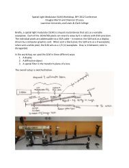
9. Wire <strong>the</strong> driver circuit as shown in Figure 5. In this experiment, a ramped voltage is<br />
applied to <strong>the</strong> driver using <strong>the</strong> signal generator on <strong>the</strong> 750 interface. However, since <strong>the</strong><br />
driver motor stalls out at low voltages and it is desired to get <strong>the</strong> maximum number of<br />
data points possible, it is necessary to have an offset voltage so <strong>the</strong> minimum voltage is<br />
about 1 V. This offset voltage is supplied by <strong>the</strong> DC power supply. Plug <strong>the</strong> driver into<br />
<strong>the</strong> DC power supply and attach <strong>the</strong> digital voltmeter across <strong>the</strong> power supply.<br />
DataStudio<br />
Function Generator Power Amplifier<br />
+<br />
DC Power<br />
Supply<br />
+<br />
+<br />
Driver<br />
Figure 5: Driver Wiring Diagram