Download the Workshop Document - comPADRE
Download the Workshop Document - comPADRE
Download the Workshop Document - comPADRE

Create successful ePaper yourself
Turn your PDF publications into a flip-book with our unique Google optimized e-Paper software.
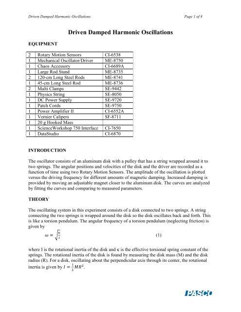
Driven Damped Harmonic Oscillations Page 1 of 8<br />
EQUIPMENT<br />
Driven Damped Harmonic Oscillations<br />
2 Rotary Motion Sensors CI-6538<br />
1 Mechanical Oscillator/Driver ME-8750<br />
1 Chaos Accessory CI-6689A<br />
1 Large Rod Stand ME-8735<br />
2 120-cm Long Steel Rods ME-8741<br />
1 45-cm Long Steel Rod ME-8736<br />
2 Multi Clamps SE-9442<br />
1 Physics String SE-8050<br />
1 DC Power Supply SE-9720<br />
1 Patch Cords SE-9750<br />
1 Power Amplifier II CI-6552A<br />
1 Vernier Calipers SF-8711<br />
1 20 g Hooked Mass<br />
1 Science<strong>Workshop</strong> 750 Interface CI-7650<br />
1 DataStudio CI-6870<br />
INTRODUCTION<br />
The oscillator consists of an aluminum disk with a pulley that has a string wrapped around it to<br />
two springs. The angular positions and velocities of <strong>the</strong> disk and <strong>the</strong> driver are recorded as a<br />
function of time using two Rotary Motion Sensors. The amplitude of <strong>the</strong> oscillation is plotted<br />
versus <strong>the</strong> driving frequency for different amounts of magnetic damping. Increased damping is<br />
provided by moving an adjustable magnet closer to <strong>the</strong> aluminum disk. The curves are analyzed<br />
by fitting <strong>the</strong> curves and comparing to measured parameters.<br />
THEORY<br />
The oscillating system in this experiment consists of a disk connected to two springs. A string<br />
connecting <strong>the</strong> two springs is wrapped around <strong>the</strong> disk so <strong>the</strong> disk oscillates back and forth. This<br />
is like a torsion pendulum. The angular frequency of a torsion pendulum (neglecting friction) is<br />
given by<br />
(1)<br />
where I is <strong>the</strong> rotational inertia of <strong>the</strong> disk and κ is <strong>the</strong> effective torsional spring constant of <strong>the</strong><br />
springs. The rotational inertia of <strong>the</strong> disk is found by measuring <strong>the</strong> disk mass (M) and <strong>the</strong> disk<br />
radius (R). For a disk, oscillating about <strong>the</strong> perpendicular axis through its center, <strong>the</strong> rotational<br />
inertia is given by .
Driven Damped Harmonic Oscillations Page 2 of 8<br />
The torsional spring constant is determined by applying a known torque (τ = rF) to <strong>the</strong> disk and<br />
measuring <strong>the</strong> resulting angle (θ) through which <strong>the</strong> disk turns. Then <strong>the</strong> spring constant is given<br />
by . (2)<br />
When <strong>the</strong> damped oscillator is driven with a sinusoidal torque, <strong>the</strong> differential equation<br />
describing its motion is<br />
(3)<br />
The solution to this equation is<br />
(4)<br />
where (5)<br />
is <strong>the</strong> phase difference between <strong>the</strong> driving torque and <strong>the</strong> resultant motion. Because <strong>the</strong> rotary<br />
motion sensor zeroes on start, we will model <strong>the</strong> angular velocity of <strong>the</strong> disk ra<strong>the</strong>r than <strong>the</strong> angle<br />
(which has an arbitrary offset). Taking <strong>the</strong> derivative yields <strong>the</strong> angular velocity:<br />
(6)<br />
The driving velocity is proportional to<br />
driving velocity can be compared:<br />
so <strong>the</strong> phases of <strong>the</strong> disk velocity and <strong>the</strong><br />
(i) As <strong>the</strong> driving frequency (ω) approaches zero, . The resulting disk<br />
velocity is in phase with <strong>the</strong> driving velocity.<br />
(ii)<br />
At resonance, ω = ω o , which results in<br />
and<br />
Therefore, <strong>the</strong> velocity is out of phase with <strong>the</strong> driving torque by 45 o .<br />
(iii) As <strong>the</strong> driving frequency (ω) goes to infinity, . The<br />
resulting velocity is 180 o out of phase with <strong>the</strong> driving torque.<br />
The velocity amplitude is dependent on <strong>the</strong> driving frequency in <strong>the</strong> following way:<br />
(7)<br />
The amplitude is a maximum for . (8)<br />
At resonance, <strong>the</strong> amplitude is . (9)
Driven Damped Harmonic Oscillations Page 3 of 8<br />
SET UP<br />
1. Mount <strong>the</strong> driver on a rod base as shown in Figure 2. Slide <strong>the</strong> first Rotary Motion Sensor<br />
onto <strong>the</strong> same rod as <strong>the</strong> driver. See Figure 3 for <strong>the</strong> orientation of <strong>the</strong> Rotary Motion<br />
Sensor.<br />
Figure 2: Driver<br />
Figure 3: Complete Setup<br />
Figure 4: String and Magnet
Driven Damped Harmonic Oscillations Page 4 of 8<br />
2. On <strong>the</strong> driver, rotate <strong>the</strong> driver arm until it is vertically downward. Attach a string to <strong>the</strong><br />
driver arm and thread <strong>the</strong> string through <strong>the</strong> string guide at <strong>the</strong> top end of <strong>the</strong> driver.<br />
Wrap <strong>the</strong> string completely around <strong>the</strong> Rotary Motion Sensor large pulley. Tie one end of<br />
one of <strong>the</strong> springs to <strong>the</strong> end of this string. Tie <strong>the</strong> end of <strong>the</strong> spring close to <strong>the</strong> Rotary<br />
Motion Sensor.<br />
3. Use two vertical rods connected by a cross rod at <strong>the</strong> top for greater stability. See Figure<br />
3.<br />
4. Mount <strong>the</strong> second Rotary Motion Sensor on <strong>the</strong> cross rod.<br />
5. Tie a short section of string (a few centimeters) to <strong>the</strong> leveling screw on <strong>the</strong> base. Tie one<br />
end of <strong>the</strong> second spring to this string.<br />
6. Cut a string to a length of about 1.5 m. Wrap <strong>the</strong> string around <strong>the</strong> middle step of <strong>the</strong><br />
second Rotary Motion Sensor twice. See Figure 4. Attach <strong>the</strong> disk to <strong>the</strong> Rotary Motion<br />
Sensor with <strong>the</strong> screw.<br />
7. To complete <strong>the</strong> setup of <strong>the</strong> springs, thread each end of <strong>the</strong> string from <strong>the</strong> pulley<br />
through <strong>the</strong> ends of <strong>the</strong> springs and tie <strong>the</strong>m off with about equal tension is each side: The<br />
disk should be able to rotate 180 degrees to ei<strong>the</strong>r side without <strong>the</strong> springs hitting <strong>the</strong><br />
Rotary Motion Sensor pulley.<br />
8. Attach <strong>the</strong> magnetic drag accessory to <strong>the</strong> side of <strong>the</strong> Rotary Motion Sensor as shown in<br />
Figure 4. Adjust <strong>the</strong> screw that has <strong>the</strong> magnet so <strong>the</strong> magnet is about 1.0 cm from <strong>the</strong><br />
disk.<br />
9. Wire <strong>the</strong> driver circuit as shown in Figure 5. In this experiment, a ramped voltage is<br />
applied to <strong>the</strong> driver using <strong>the</strong> signal generator on <strong>the</strong> 750 interface. However, since <strong>the</strong><br />
driver motor stalls out at low voltages and it is desired to get <strong>the</strong> maximum number of<br />
data points possible, it is necessary to have an offset voltage so <strong>the</strong> minimum voltage is<br />
about 1 V. This offset voltage is supplied by <strong>the</strong> DC power supply. Plug <strong>the</strong> driver into<br />
<strong>the</strong> DC power supply and attach <strong>the</strong> digital voltmeter across <strong>the</strong> power supply.<br />
DataStudio<br />
Function Generator Power Amplifier<br />
+<br />
DC Power<br />
Supply<br />
+<br />
+<br />
Driver<br />
Figure 5: Driver Wiring Diagram
Driven Damped Harmonic Oscillations Page 5 of 8<br />
10. Plug <strong>the</strong> disk Rotary Motion Sensor into Channels 1 and 2 on <strong>the</strong> Science<strong>Workshop</strong> 750<br />
interface with <strong>the</strong> yellow plug in Channel 1. Plug <strong>the</strong> driver Rotary Motion Sensor into<br />
Channels 3 and 4 with <strong>the</strong> yellow plug in Channel 3. Plug <strong>the</strong> Power Amplifier into<br />
Channel A.<br />
11. Open <strong>the</strong> DataStudio file called "Driven Harmonic.ds".<br />
PROCEDURE<br />
1. Measure <strong>the</strong> resonant frequency. Leave <strong>the</strong> DC power supply turned off and click <strong>the</strong><br />
signal generator off in DataStudio. Screw <strong>the</strong> magnet back away from <strong>the</strong> disk as far as<br />
possible. Click on START, displace <strong>the</strong> disk, and let it oscillate. Click on STOP. Measure<br />
<strong>the</strong> period using <strong>the</strong> Smart cursor on <strong>the</strong> disk oscillation graph. Repeat for <strong>the</strong> magnet 1<br />
cm away from <strong>the</strong> disk. A good way to space <strong>the</strong> magnet is to get a stack of paper that is<br />
measured to be 1 cm thick and insert it between <strong>the</strong> magnet and <strong>the</strong> disk to judge <strong>the</strong><br />
spacing.<br />
The resonant frequency for with no magnet is 0.47 Hz.<br />
2. Determine <strong>the</strong> spring constant. Click on START. Hang a hooked mass (20 g) on <strong>the</strong> top<br />
of one of <strong>the</strong> springs and measure <strong>the</strong> resulting angle<br />
through which <strong>the</strong> disk rotates. Click on STOP. Measure<br />
<strong>the</strong> radius of <strong>the</strong> middle step of <strong>the</strong> RMS pulley and<br />
calculate <strong>the</strong> torque caused by <strong>the</strong> weight of <strong>the</strong> 20 g<br />
mass. Calculate <strong>the</strong> torsional spring constant using<br />
Equation (2).
Driven Damped Harmonic Oscillations Page 6 of 8<br />
3. Determine <strong>the</strong> rotational inertia. Remove <strong>the</strong> disk and measure <strong>the</strong> mass and radius of<br />
<strong>the</strong> disk. Calculate <strong>the</strong> rotational inertia of <strong>the</strong> disk.<br />
4. Amplitude vs. Frequency: Turn on <strong>the</strong> DC power supply and set <strong>the</strong> voltage on 1 V.<br />
Click on Auto on <strong>the</strong> signal generator in DataStudio. Click on START in DataStudio.<br />
Since <strong>the</strong> frequency of <strong>the</strong> signal generator ramp is set for 0.001 Hz, data collection will<br />
take 1000 seconds (16.7 minutes). Then click on STOP.<br />
5. Adjust <strong>the</strong> magnetic damping screw to about 0.5 cm from <strong>the</strong> disk and repeat <strong>the</strong> data<br />
collection.<br />
6. Adjust <strong>the</strong> magnetic damping screw to about 0.2 cm from <strong>the</strong> disk and repeat <strong>the</strong> data<br />
collection.<br />
7. Adjust <strong>the</strong> magnetic damping screw to about 0.1 cm from <strong>the</strong> disk and repeat <strong>the</strong> data<br />
collection.<br />
ANALYSIS<br />
1. Theoretical Resonant Frequency: Using <strong>the</strong> torsional spring constant and <strong>the</strong> disk<br />
rotational inertia, calculate <strong>the</strong> <strong>the</strong>oretical period and <strong>the</strong> resonant frequency of <strong>the</strong><br />
oscillator (ignoring friction).<br />
and<br />
2. Effect of Damping on <strong>the</strong> Resonance Curve: Examine <strong>the</strong> resonance curves for<br />
different amounts of damping. How does increasing <strong>the</strong> damping affect <strong>the</strong> shape of <strong>the</strong><br />
curve (<strong>the</strong> width, maximum amplitude, frequency of <strong>the</strong> maximum)<br />
From Equation (8):<br />
Solving for <strong>the</strong> damping<br />
coefficient:<br />
Substituting for <strong>the</strong> frequencies<br />
gives:
Driven Damped Harmonic Oscillations Page 7 of 8<br />
Use Equation (7) to calculate a model which fits <strong>the</strong> data.<br />
(7)<br />
To fit <strong>the</strong> data to <strong>the</strong> <strong>the</strong>ory, <strong>the</strong> damping coefficients do not match:<br />
Parameter Calculated from Theory Theoretical Model Fit to Data<br />
Maximum Amplitude ---- 13.65 rad/s<br />
Disk Rotational Inertia 1.34×10 -4 kgm 2 1.34×10 -4 kgm 2<br />
Damping Coefficient 1.85×10 -4 kgm 2 /s 1.23×10 -4 kgm 2 /s<br />
Resonant Frequency 0.490 Hz (without friction) 0.466 Hz (with friction)<br />
One consideration is that <strong>the</strong> damping consists of both magnetic damping and bearing drag. Also,<br />
<strong>the</strong>re is a small component of rotational inertia in <strong>the</strong> Rotary Motion Sensor which is not<br />
accounted for when calculating <strong>the</strong> rotational inertia of <strong>the</strong> disk.<br />
3. Is <strong>the</strong> resonant frequency for <strong>the</strong> least amount damping <strong>the</strong> same as <strong>the</strong> <strong>the</strong>oretical<br />
frequency Calculate <strong>the</strong> percent difference.<br />
No, <strong>the</strong> resonant frequency with damping is 0.466 Hz and <strong>the</strong> <strong>the</strong>oretical resonant<br />
frequency without damping is 0.490 Hz. The frequency with damping is lower as<br />
expected. The % difference is 4.9%.<br />
4. Why is <strong>the</strong> resonance curve asymmetrical about <strong>the</strong> resonant frequency<br />
The lower limit for <strong>the</strong> frequency is zero but <strong>the</strong> upper limit is infinity. So <strong>the</strong> curve goes<br />
asymptotically to zero at zero frequency and at infinite frequency and thus is not<br />
symmetrical about <strong>the</strong> resonant frequency.
Driven Damped Harmonic Oscillations Page 8 of 8<br />
5. Examine <strong>the</strong> graphs of <strong>the</strong> driving oscillation versus time and <strong>the</strong> disk oscillation versus<br />
time. Measure <strong>the</strong> phase difference between <strong>the</strong>se oscillations at high frequency (at <strong>the</strong><br />
beginning of <strong>the</strong> time), resonance frequency (at <strong>the</strong> time when <strong>the</strong> disk oscillation is<br />
greatest), and at low frequency (at <strong>the</strong> end of <strong>the</strong> time). Do <strong>the</strong>se phase differences agree<br />
with <strong>the</strong> <strong>the</strong>ory<br />
For low frequency, <strong>the</strong> disk is nearly in phase with <strong>the</strong> driver.<br />
At resonance, <strong>the</strong> disk is 90 o out of phase with <strong>the</strong> driver.<br />
At high frequency, <strong>the</strong> disk is nearly 180 o out of phase with<br />
<strong>the</strong> driver.