Download the Workshop Document - comPADRE
Download the Workshop Document - comPADRE
Download the Workshop Document - comPADRE
- No tags were found...

You also want an ePaper? Increase the reach of your titles
YUMPU automatically turns print PDFs into web optimized ePapers that Google loves.
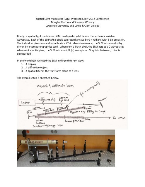
Spatial Light Modulator (SLM) <strong>Workshop</strong>, BFY 2012 ConferenceDouglas Martin and Shannon O’LearyLawrence University and Lewis & Clark CollegeBriefly, a spatial light modulator (SLM) is a liquid crystal device that acts as a variablewaveplate. Each of <strong>the</strong> 1024x768 pixels can retard a wave by 0‐ radians with 8 bit precision.The individual pixels are addressable via a VGA cable – in essence, <strong>the</strong> SLM acts as a displaydriven by a computer graphics card. When sent a black pixel, <strong>the</strong> SLM acts as a 0 waveplate;when sent a white pixel, <strong>the</strong> SLM acts as a /2 () waveplate. Gray is in between; color isdisregarded.In <strong>the</strong> workshop, we used <strong>the</strong> SLM in three different ways:1. A display2. A diffractive object3. A spatial filter in <strong>the</strong> transform plane of a lens.The overall setup is sketched below.
1. SLM as video display.We use a laptop to drive <strong>the</strong> SLM. The SLM acts as a second monitor, but <strong>the</strong> SLM itself onlychanges <strong>the</strong> phase of <strong>the</strong> reflected light. To change <strong>the</strong> amplitude (and see something), a pairof polarizers is necessary. Steps to get <strong>the</strong> SLM up and running:a) Plug SLM power in (this turns <strong>the</strong> SLM on)b) Connect <strong>the</strong> SLM video in to <strong>the</strong> laptop video out with a VGA cable.c) Setup <strong>the</strong> laptop to drive a second monitor (in Windows, we extend <strong>the</strong> desktop onto<strong>the</strong> 2 nd monitor).d) With <strong>the</strong> SLM’s taped‐on polarizer in place, you should be able to see <strong>the</strong> desktopbackground by directly looking at <strong>the</strong> SLM (it will be tiny).e) Setup <strong>the</strong> optical system sketched above, without <strong>the</strong> “object” or 200 mm lens on <strong>the</strong>incoming rail. The beam expander just after <strong>the</strong> laser should be used to create acollimated beam, parallel to <strong>the</strong> incident rail and optical bench, that covers (or just overfills)<strong>the</strong> SLM surface. An iris placed on <strong>the</strong> rail (on a rail carrier, at <strong>the</strong> right height), canhelp align <strong>the</strong> beam. The beam reflected of <strong>the</strong> SLM should be parallel to <strong>the</strong> opticaltable and <strong>the</strong> outgoing rail.f) Remove <strong>the</strong> taped‐on polarizer (but save). Use <strong>the</strong> 100 mm lens after <strong>the</strong> SLM to createan image of <strong>the</strong> SLM surface on a far screen (we use a wall 5‐10 ft away).g) Linearly polarize <strong>the</strong> incident light (polarized laser or polaroid) and <strong>the</strong>n rotate <strong>the</strong> linearpolarizer in <strong>the</strong> output beam until <strong>the</strong> display is as crisp as possible. The incomingpolarization matters – so you may need to rotate <strong>the</strong> incoming polarization as well.h) To control what is sent to <strong>the</strong> SLM, we use PowerPoint. In Windows, under <strong>the</strong> “SlideShow” menu is an option “Show On” – use <strong>the</strong> drop‐down menu to select seconddisplay. Then, a PowerPoint slideshow will be sent to <strong>the</strong> SLM (<strong>the</strong> second display). Wetend to play around with black and white objects, but gray scale works as well (color isignored).2. SLM as diffractive object.The SLM acts as an aperture for incident light – a phase aperture if no polarizers are present, oran amplitude aperture if polarizers are in place, as in #1 above. Removing <strong>the</strong> 100 mm lens willcause <strong>the</strong> diffraction pattern of <strong>the</strong> aperture to appear on <strong>the</strong> far screen (at infinity). Thatdiffraction pattern can be brought onto a screen placed a finite distance away using a lens.In <strong>the</strong> workshop, we used <strong>the</strong> SLM to create a 2‐slit aperture (two white lines on a blackbackground in PowerPoint), a 4‐slit aperture, a quasi‐crystal aperture, and a computergenerated hologram aperture. On <strong>the</strong> far screen, <strong>the</strong> diffraction patterns of <strong>the</strong>se apertureswere formed. Steps to get use <strong>the</strong> SLM as a diffractive aperture:a) Remove <strong>the</strong> beam expansion optics (<strong>the</strong> microscope objective and 200 mm lens) – useof a post collar on <strong>the</strong> post will help with realignment later.b) Now <strong>the</strong> unexpanded beam should be incident on a small portion of <strong>the</strong> SLM surface.With <strong>the</strong> 100 mm lens in place to image <strong>the</strong> surface of <strong>the</strong> SLM, use PowerPoint to putyour favorite diffraction aperture on <strong>the</strong> SLM surface. The far screen should show <strong>the</strong>aperture. You may need to move <strong>the</strong> aperture in PowerPoint to ensure it is centered in<strong>the</strong> incident beam. With <strong>the</strong> slideshow running, click on an object in PowerPoint (say,
<strong>the</strong> vertical line). Then, use <strong>the</strong> arrow keys to move it around. The object will be movedaround on <strong>the</strong> SLM surface. To continue <strong>the</strong> slideshow, be sure to click <strong>the</strong> small box“resume slideshow.”c) Remove <strong>the</strong> 100 mm lens, and <strong>the</strong> diffraction pattern should appear on <strong>the</strong> far screen.d) Vary <strong>the</strong> aperture as desired (we changed <strong>the</strong> slit‐width, inserted a quasicrystal, andused a computer generated hologram following Thad Walker, http://wwwatoms.physics.wisc.edu/papers/holo.pdf,using <strong>the</strong> MATLAB code in this posthttp://tinyurl.com/d662n7o).e) It is possible to create a sharper diffraction pattern. Re‐insert <strong>the</strong> 100 mm lens – <strong>the</strong>diffraction pattern will appear in <strong>the</strong> transform plane, one focal length downstream.Use a second lens (short focal length, say 50 or 100 mm) to magnify <strong>the</strong> transform planeonto a far screen.f) Note that <strong>the</strong> diffraction pattern remains <strong>the</strong> same with an amplitude aperture (withpolarizers in place) or phase aperture (without polarizers in place). Hecht has a nicediscussion in section 11.3.3 of Optics, 4 th ed.3. SLM as spatial filter.By inserting <strong>the</strong> SLM in <strong>the</strong> transform plane of a lens, <strong>the</strong> SLM can be used to manipulate <strong>the</strong>Fourier transform of an object. In <strong>the</strong> workshop, we used <strong>the</strong> SLM as a variable amplitudeaperture (with polarizers) to remove a kitty from its cage by removing <strong>the</strong> cage information in<strong>the</strong> transform plane. Steps to get <strong>the</strong> SLM working as a spatial filter:a) Re‐expand <strong>the</strong> incoming beam, using <strong>the</strong> microscope objective and 200 mm lens.b) Print your object on a transparency – we used a picture of a kitten in a cage with withlines spaced about 0.5 mm apart. The narrower <strong>the</strong> line spacing, <strong>the</strong> wider <strong>the</strong> spots in<strong>the</strong> diffraction pattern, and vice versa.c) Place <strong>the</strong> transparency in <strong>the</strong> beam along <strong>the</strong> incident rail, more than 200 mm from <strong>the</strong>SLM. Insert a 200 mm lens on <strong>the</strong> rail exactly 200 mm before <strong>the</strong> SLM surface. Toensure <strong>the</strong> transform plane is on <strong>the</strong> SLM surface, <strong>the</strong> following trick may be helpful.First, remove <strong>the</strong> transparency and <strong>the</strong> 200 mm lens, and send a crisp image to <strong>the</strong> SLM.Use <strong>the</strong> 100 mm lens after <strong>the</strong> SLM to focus <strong>the</strong> surface of <strong>the</strong> SLM onto a far screen.Now, change <strong>the</strong> PowerPoint slide to a blank, white slide. Re‐insert <strong>the</strong> transparencywith object and <strong>the</strong> 200 mm lens into <strong>the</strong> incident beam. Move <strong>the</strong> 200 mm lens (not<strong>the</strong> 100 mm lens) until <strong>the</strong> Fourier transform of <strong>the</strong> object, viewed on <strong>the</strong> far screen, isin crisp focus. Since <strong>the</strong> far screen is an image of <strong>the</strong> SLM surface, when <strong>the</strong> transformis exactly on <strong>the</strong> SLM, it will also be enlarged and in focus on <strong>the</strong> far wall.d) Insert your spatial filtering aperture into PowerPoint. You can create a complicatedaperture – but positioning is difficult (<strong>the</strong> SLM pixels are about 10 m across).Alternately, as we did in <strong>the</strong> workshop, black bars can be used to filter an entire row ofspots. In our case, we arranged <strong>the</strong> cage so that <strong>the</strong> bars were vertical. The transform,<strong>the</strong>refore, appeared as horizontal line of spots. The spots on ei<strong>the</strong>r side of <strong>the</strong> zeroorderwere removed with black bars, positioned in PowerPoint (ano<strong>the</strong>r trick: holdingdown <strong>the</strong> control key (Windows) while using <strong>the</strong> arrow keys to move objects aroundwithin PowerPoint allows for very fine control of object position).
e) To see <strong>the</strong> result, remove <strong>the</strong> 100 mm lens in <strong>the</strong> outgoing beam path. We use a blankslide immediately after <strong>the</strong> spatial filter slide to be able to go back and forth betweenfiltered and unfiltered image in PowerPoint.f) A few notes: at 633 nm (red He‐Ne), <strong>the</strong> SLM can only delay <strong>the</strong> phase by 0.8 ,resulting in an imperfect amplitude aperture. Shifting to green (543 nm He‐Ne or 532nm DPSS) allows <strong>the</strong> phase delay to be increased to closer to (0.95 at 532 nm). Thismay help improve <strong>the</strong> aperture filtering. O<strong>the</strong>r fun filters include a low‐pass filter(simply a small white circle on a black background – this removes <strong>the</strong> high‐frequencyinformation, resulting in a blurred image; a high‐pass filter (small black circle on a whitebackground), which removes <strong>the</strong> DC component (that is, <strong>the</strong> mean intensity), whichtends to make dark regions bright and vice versa; and a “razor‐blade” filter, with twolarge black rectangles surrounding a narrow white slit – using this and a square‐gridobject allows ei<strong>the</strong>r <strong>the</strong> horizontal or vertical lines of <strong>the</strong> grid to be removed (in fact, afilter with actual razor blades in <strong>the</strong> transform plane, no SLM, works fantastically for thisspatial filter).Doug Martindouglas.s.martin@lawrence.eduShannon O’Learysoleary@lclark.edu
Parts List used in <strong>the</strong> workshopPart Source ApproxCost.5 mW polarized HeNe Thorlabs HNL050L $1300or 5 mW laser pointer eBay, etc. (downside: ugly beam profile) $15Spatial Light Modulator Cambridge Correlators SDE1024 $10002’ x 4’ x 2” breadboard Vere 24482E1FM $9302 x 24” rails Thorlabs RLA2400 $2805 x rail carriers Thorlabs RC1 $1154 x post holder bases Thorlabs BA1S $204 x base clamps Thorlabs CL5 $166 x 2” post holders Thorlabs PH2 $471 x 1” post holder Thorlabs PH1 $72 x 3” post holders Thorlabs PH3 $171 x 1” post Thorlabs TR1 $58 x 2” posts Thorlabs TR2 $421 x 1” f=100 mm plano‐convex Thorlabs LA1509 $20lens2 x 1” f=200 mm plano‐convex Thorlabs LA1708 $40lenses3 x lens mounts Thorlabs LMR1 $472 x 1” glass linear polarizer Edmund Optics NT54‐926 $502 x rotation mount Thorlabs RSP1 $1601 x kinematic mirror mount Thorlabs KM100 $401 x 1” round mirror Thorlabs ME1‐G01 $141 x 10x microscope objective Newport L‐10X $2001 x microscope objectivemountThorlabs OMR $251 x iris Thorlabs ID25 $53screws & allen wrenches Thorlabs HW‐Kit2 & CCHK$140or McMaster‐Carr$40images on transparencyLaptop to drive SLMA few notes:eBay is a great source for used optomechanics – we’ve had good luck with used parts. Usedoptical breadboards can also save quite a bit of money.Thorlabs offers a “new lab” discount, typically around 10% ‐ ask for it if you decide to set up anew SLM lab.Any laser with good beam quality will work, but <strong>the</strong> liquid crystal in <strong>the</strong> SLM is apparentlydegraded by UV light – so 405 nm may not be a wise choice.With just a little more equipment (~$500‐1000 more), we run an entire optics course of labs.