Download the Workshop Document - comPADRE
Download the Workshop Document - comPADRE
Download the Workshop Document - comPADRE
- No tags were found...
You also want an ePaper? Increase the reach of your titles
YUMPU automatically turns print PDFs into web optimized ePapers that Google loves.
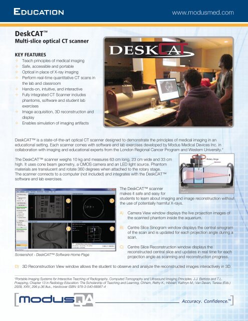
BEGINNER LAB EXERCISES± Lab 0: Introduction to DeskCATIn this lab, students will scan a simple 3D object (i.e. a mouse phantom) tobecome familiar with <strong>the</strong> DeskCAT scanner procedures and software interface.This will help students become oriented with <strong>the</strong> operations of a CT scannerand associated software for data capture, image reconstruction, and 3D imagedisplay.This exercise will introduce <strong>the</strong> students to <strong>the</strong> user interface of <strong>the</strong> DeskCATscanner, explain <strong>the</strong> concept of a reference versus data scan, and allow <strong>the</strong>m toexplore <strong>the</strong> different navigational and visualization tools that <strong>the</strong> software offersfor both 2D projections and 3D reconstructions.± Lab 1: Introduction to Medical Imaging – 3D LocalizationIn this lab, students will make geometric measurements of <strong>the</strong> 3D positions offiducial markers embedded in a cylindrical phantom. Measurements are madefrom 2 orthogonal radiographic (camera) projections, as well as from a CTreconstructed 3D image. Students can compare and contrast <strong>the</strong> two imagingmodalities with calculations of coordinates by each approach. By <strong>the</strong> end of <strong>the</strong>lab, students should find that <strong>the</strong> marker positions are in close agreement usingan orthogonal pair of 2D radiographic images and <strong>the</strong> full 3D CT image.This exercise will fur<strong>the</strong>r introduce <strong>the</strong> students to <strong>the</strong> user interface of <strong>the</strong>DeskCAT scanner. Students will determine <strong>the</strong> geometric positions of fiducialmarkers in 3D space, and will also learn how to adjust window and level toimprove visibility of targets in an image.± Lab 2: System LinearityIn this lab, students will perform an experiment to assess <strong>the</strong> linearity of <strong>the</strong>DeskCAT scanner performance. Students are given a water-filled jar andconcentrated black dye solution. They must acquire a data-set of scans withincreasing optical attenuation coefficients. By <strong>the</strong> end of <strong>the</strong> lab, students shouldobserve a linear trend and accurate reconstructions to within 10%, with resultsdepending on <strong>the</strong> concentration of <strong>the</strong> dye. Students must identify sources oferror and offer suggestions to reduce <strong>the</strong> experimental error.This exercise will illustrate <strong>the</strong> importance of an imaging system’s linearity on itssuitability as a quantitative tool.± Lab 3: Spatial Resolution and Modulation Transfer Function (MTF)In this lab, <strong>the</strong> student will assess <strong>the</strong> spatial resolution of <strong>the</strong> DeskCATscanner at 2 levels: The spatial resolution of a single 2D projection radiographicimage, and <strong>the</strong> spatial resolution of a 3D CT reconstructed image. Studentswill acquire images of a test bar pattern with a series of “picket fence” linethicknesses. By measuring <strong>the</strong> contrast of line pairs, students plot pixel intensity(or modulation) vs. spatial frequency to estimate <strong>the</strong> shape of <strong>the</strong> modulationtransfer function (MTF).This exercise will introduce students to <strong>the</strong> concept of MTF, its practicalimplications and demonstrate one method of measuring it.© 2012 Modus Medical Devices Inc. Version 1.1 Modus Medical Devices Inc. reserves <strong>the</strong> right to make changes without notice and shall not be liable for any errors or omissions contained in this document.
INTERMEDIATE LAB EXERCISES± Lab 4: Edge Response, Point Spread Function and MTFIn this lab, students will apply a more ma<strong>the</strong>matical technique to determine <strong>the</strong>modulation transfer function and compare results with <strong>the</strong> methods used in Lab#3. Students will use a step-edge phantom to measure pixel profiles across <strong>the</strong>contrasted edge. Using Fourier transform methods, students will calculate andplot <strong>the</strong> MTF for <strong>the</strong> radiographic and CT images. By <strong>the</strong> end of <strong>the</strong> lab, studentswill be able to compare <strong>the</strong> results for on-axis and off-axis slice locations in <strong>the</strong>3D image with <strong>the</strong> previous results obtained from Lab #3.This exercise will help students learn how to use Fourier methods to determine<strong>the</strong> image resolution limits of a CT scanner. To facilitate implementation ofthis lab, MATLAB® code is provided to analyze <strong>the</strong> edge response curve andperform <strong>the</strong> necessary Fourier transforms.± Lab 5: Contrast to Noise RatioIn this lab, students will learn <strong>the</strong> importance of contrast and noise as it isobserved in low-dose imaging. A lower dose image of a finger phantomcontaining several small pins of different opacity is simulated by addingGaussian noise to <strong>the</strong> projection images in sinogram space. By <strong>the</strong> end of<strong>the</strong> lab, students should observe that for high noise (i.e. low dose) conditions,<strong>the</strong> ability to resolve low contrast pins is progressively impaired as noise isincreased. This is an important topic in view of <strong>the</strong> “Image Gently”(www.pedrad.org) approach used in medical diagnostic imaging.This exercise will help students understand <strong>the</strong> compromise between what isnecessary to achieve visualization of low contrast targets and level of radiationexposure.± Lab 6: Image Artifacts due to Faulty Detectors and Missing ProjectionsIn this lab, students will learn that CT images are not a perfect rendition of <strong>the</strong>object scanned. In a real CT scanner, <strong>the</strong> transmission of X-rays is measured byreal detectors with inherent noise and possible faults. Students will manipulate<strong>the</strong> DeskCAT software to remove user-selected camera pixels, including entirerows or columns of pixels (i.e. corrupt radiograph and sinogram). In addition,angular projections can be eliminated from <strong>the</strong> sinogram. Students will observea variety of artifacts (e.g. rings, spokes) in <strong>the</strong> reconstructed CT images and areasked to offer explanations.Bad pixelResolutionSettingVoxel Size(mm)ReconstructedImage Size (MB)Acquisition &Reconstruction Time (min)*ADVANCED LAB EXERCISES(available as a package, Fall 2012)Low 2 0.25
Accuracy. Confidence.DELIVERABLES± Scanner± Phantoms± Empty Jars (3)± Food Coloring (Dye)± Syringes (20mL and 5mL)± Cables± Power SupplyDOCUMENTATION± Software CD± User’s Guide± Student Lab ExercisesEDUCATIONA safe way to learnabout Medical ImagingORDERING INFORMATION100-2020 DeskCAT Optical CT System, includes:± Scanner with Rotary Stage and Jar Clamp± Software CD & <strong>Document</strong>ation± Phantoms: • Fiducial,• Resolution• Blank Silicone± Empty Jars (3)± Food Coloring (Dye)± Syringes (20mL and 5mL)± Labs 1, 2 & 3± Cables: • USB-A to USB- mini B• USB-A to USB-B± Power Supply (Elpac Power Systems 50Wswitching power adapter model FWC5024F: 110 - 240 V~, 50 - 60 Hz, 1.0A;Unit input: 24Vdc, 2.1A.)± Auxiliary Power Cable (3.5mm audioconnector)ADDITIONAL ORDERING INFORMATION500-2100 Labs 4, 5 & 6500-2105 Labs 7, 8 & 9 (available Fall 2012)SPECIFICATIONS± Dimensions: 63cm x 23cm x 33cm (25” x 9” x 13”)± Weight: 10kg (22lbs)MINIMUM TECHNICAL REQUIREMENTS± Standard desktop or laptop PC with Windows 7/ Vista(recommended x64), or XP± 1 GB RAM± .NET framework 3.5± 2 USB portsCONTACT INFORMATIONToll Free: (866) 862-9682 (North America)Phone: +1 (519) 438-2409Fax: +1 (519) 643-0127info@deskcat.comwww.modusmed.comModus Medical Devices Inc. 1570 North Routledge Park, | London, Ontario | Canada N6H 5L6


