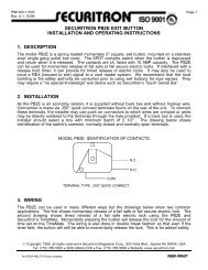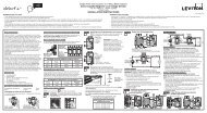
securitron pb, pba exit button installation and operating instructions ...
securitron pb, pba exit button installation and operating instructions ...
securitron pb, pba exit button installation and operating instructions ...

Create successful ePaper yourself
Turn your PDF publications into a flip-book with our unique Google optimized e-Paper software.
Securitron Magnalock Corp. Tel 775.355.5625<br />
550 Vista Boulevard Fax 775.355.5633<br />
Sparks, NV 89434<br />
info@<strong>securitron</strong>.com<br />
www.<strong>securitron</strong>.com<br />
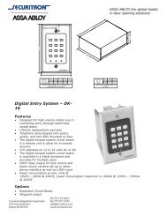
ASSA ABLOY, the global leader<br />
in door opening solutions<br />
SECURITRON PB, PBA EXIT BUTTON<br />
INSTALLATION AND OPERATING INSTRUCTIONS<br />
1. DESCRIPTION<br />
The model PB is a spring loaded momentary, 1 1/2" Diameter, <strong>exit</strong> <strong>button</strong>, with bi-color<br />
illumination, mounted on a stainless steel single gang outlet box cover. The model PBA is<br />
alternate action (push-on; push off). The NO <strong>and</strong> NC (DPST) contacts switch when the <strong>button</strong> is<br />
depressed <strong>and</strong> return when it is released. The contacts are UL listed with 7 AMP capacity. The<br />
indicator LED <strong>and</strong> the switch LED can be individually operated according to the needs of the<br />
<strong>installation</strong>. The indicator LED is mounted above the <strong>button</strong> <strong>and</strong> the switch LED illuminates the<br />
<strong>button</strong> itself. The PB can be used for momentary release of fail safe or fail secure electric locks.<br />
If interfaced with a release hold timer, it can provide for timed release of electric locks. It may<br />
also be used to input a REX (request to <strong>exit</strong>) signal to a card reader system. We recommend<br />
that the local building or fire safety authority be consulted prior to using <strong>exit</strong> <strong>button</strong>s for door<br />
egress. They may require a "no special knowledge" <strong>exit</strong> device such as Securitron's Touch<br />
Sense Bar.<br />
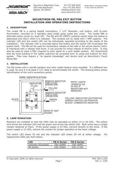
2. INSTALLATION<br />
The PB comes with a retrofit backbox <strong>and</strong> color coded hookup wires installed. If a different box<br />
is used, be sure it is at least 2 1/2" deep to accommodate the switch. The drawing below shows<br />
identification of the unit's connection points.<br />
BLACK<br />
WIRE IDENTIFICATION<br />
REMOVE RESISTOR<br />
INDICATOR FOR 12 VDC<br />
OPERATION<br />
LED<br />
YELLOW<br />
NC<br />
B<br />
NO<br />
A<br />
REMOVE RESISTOR<br />
FOR 12 VDC<br />
OPERATION<br />
GREEN<br />
NOTE: LIGHTS<br />
OPERATE ON<br />
24 VDC IF<br />
RESISTORS NOT<br />
REMOVED<br />
YELLOW= INDICATOR LED POSITIVE<br />
GREEN= SWITCH LED POSITIVE<br />
BLACK= COMMON DC NEGATIVE<br />
NC<br />
NO<br />
REAR OF UNIT<br />
SHOWN<br />
3. LAMP OPERATION<br />
Resistors are installed so that the LEDs may be operated on either 12 or 24 VDC. The yellow<br />
wire drives the indicator LED <strong>and</strong> the green wire drives the switch LED. Both wires have a single<br />
resistor soldered on them. If the power supply is 24 VDC, connect directly to the wires. If the<br />
power supply is 12 VDC, remove the resistor for proper operation at the lower voltage.<br />
The switch LED draws 30 mA <strong>and</strong> the indicator LED draws 20 mA at either voltage. For<br />
replacement LEDs see chart below:<br />
LED PB-G Series PB-R Series<br />
Indicator (Keyplate) 700-10095 700-10097<br />
PB Switch 030-10900 030-11100<br />
© Copyright, 2009, all rights reserved PN# 500-11200<br />
Page 1 Rev. C, 2/09
The Switch LED is replaced by unscrewing the mushroom cap <strong>and</strong> using a pencil with an eraser,<br />
pressing <strong>and</strong> turning the bayonet mount LED until it pops out.<br />
4. WIRING<br />
The PB can be used in many different ways but the drawings below show two common<br />
applications. The first shows momentary release of a fail safe or fail secure electric lock. The PB<br />
indicators are connected so that the switch <strong>button</strong> illuminator is normally on. When the <strong>button</strong><br />
is pressed, releasing the lock, the switch LED turns off <strong>and</strong> the indicator LED comes on. The<br />
second drawing shows timed release of a fail safe electric lock using the PB <strong>and</strong> Securitron's<br />
TimeMate. Momentarily pressing the <strong>button</strong> will release the lock for the amount of time set on<br />
the TimeMate. The LEDs will switch colors during the lock release period. The wiring is also<br />
done in double break fashion so that even if the timer fails, the <strong>button</strong> will still be able to<br />
momentarily release the lock. This is for added safety.<br />
MOMENTARY RELEASE OF FAIL SAFE OR FAIL SECURE ELECTRIC LOCK<br />
POWER<br />
SUPPLY<br />
NC<br />
IF FAIL SAFE<br />
+<br />
GREEN<br />
+<br />
NC<br />
PB ELECTRIC<br />
NO<br />
IF FAIL SECURE<br />
+<br />
D.C. LOCK<br />
NO YELLOW<br />
BLACK<br />
TIMED DOUBLE BREAK RELEASE OF FAIL SAFE LOCK<br />
POWER<br />
SUPPLY<br />
+<br />
NO<br />
GREEN<br />
YELLOW<br />
PB<br />
NC<br />
BLACK<br />
NO<br />
NC<br />
YELLOW<br />
WHITE<br />
RED<br />
BLUE<br />
TIMEMATE<br />
GREEN<br />
+<br />
FAIL SAFE<br />
D.C. LOCK<br />
BLACK<br />
PN# 500-11200<br />
Page 2 Rev. C, 2/09