3-Way Switch
3-Way Switch
3-Way Switch
- No tags were found...

Create successful ePaper yourself
Turn your PDF publications into a flip-book with our unique Google optimized e-Paper software.
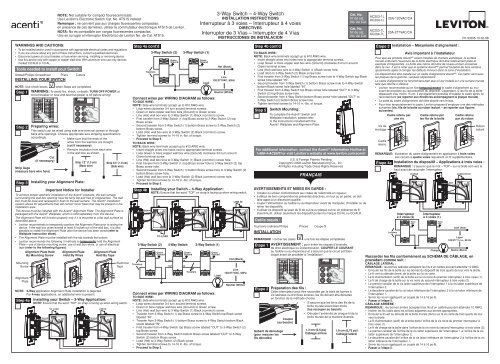
NOTE: Not suitable for compact flourescent loads.Use Levition's Electronic <strong>Switch</strong> Cat. No. ATS15 instead.Remarque : ne convient pas aux charges fluorescentes compactes;en présence de ces dernières, utiliser le commutateur électronique ATS15 de Leviton.NOTA: No es compatible con cargas fluorescentes compactas.Use en su lugar el interruptor Electrónico de Leviton No. de Cat. ATS15.3-<strong>Way</strong> <strong>Switch</strong> – 4-<strong>Way</strong> <strong>Switch</strong>INSTALLATION INSTRUCTIONSInterrupteur à 3 voies – Interrupteur à 4 voiesDIRECTIVESInterruptor de 3 Vías – Interruptor de 4 VíasINSTRUCCIONES DE INSTALACIONCat. No.N o de cat.No. de Cat.Cat. No.N o de cat.No. de Cat.AC203-1LAC204-1LAC203-7LAC204-7L20A-120VAC/CA20A-277VAC/CAPK-93395-10-02-0BWARNINGS AND CAUTIONS:• To be installed and/or used in accordance with appropriate electrical codes and regulations.• If you are unsure about any part of these instructions, consult a qualified electrician.• Disconnect power at circuit breaker or fuse when servicing, installing or removing device.• Use this device only with copper or copper clad wire. With aluminum wire use only devicesmarked CO/ALR or CU/AL.Tools needed to install your <strong>Switch</strong>:Slotted/Phillips Screwdriver Pliers CuttersINSTALLING YOUR SWITCHNOTE: Use check boxes when Steps are completed.Step 1 WARNING: To avoid fire, shock, or death; turn off power atcircuit breaker or fuse and test that power is off before wiring!Step 2Preparing wires:This switch can be wired using side wire terminal screws or throughback wire openings. Choose appropriate wire stripping specificationsaccordingly.• Make sure that the ends of thewires from the wall box are straight(cut if necessary).• Remove insulation from each wirein the wall box as shown.Cut(if necessary)Strip Gage(measure bare wire here)Step 3MountingScrewAlignmentPlateStep 4aInstalling your Alignment Plate:Alignment Plate HeldBy Mounting ScrewStrip 1/2" (1.3 cm)(Back wire)Strip 3/4" (1.9 cm)(Side wire)Installing your <strong>Switch</strong> – 3-<strong>Way</strong> Application:NOTE: Ensure that the word “TOP” on strap is facing up when wiring switch.GroundImportant Notice for InstallerTo achieve proper aesthetic installation of the Acenti ® products, the wall surfacesurrounding the wall box opening must be fairly flat and free of irregularities. The wallbox must be level and recessed or flush to the wall surface. The Acenti ® installationsystem allows for adjustments that will correct minor flaws that may be present in theinstallation area.This device must be installed with the Acenti ® Alignment Plate. The Alignment Plate ispackaged with the Acenti ® Wallplate, which is sold separately from this device.The Alignment Plate will function properly only if it is mounted to a flat wall surface asdescribed above.• Leviton recommends to temporarily position the Alignment Plate prior to wiring thedevice. If the wall box wires extend at least 6 inches out of the wall box, it is alsopossible to install the Alignment Plate after the device has been wired (refer toWallplate instruction sheet).• The Alignment Plate must be installed with the tab towards the bottom.• Leviton recommends the following 3 methods to temporarily hold the AlignmentPlate – use of device mounting screw, use of wall box wires, or use of electricaltape (refer to the following figures):TO LOADAlignment PlateHeld By WiresNOTE: 3-<strong>Way</strong> application Alignment Plate installation is depicted.For 4-way applications, an additional wire is present.GroundAlignment PlateHeld By TapeLINE INElectricalTapeStep 4a cont'dTravelers3-<strong>Way</strong> <strong>Switch</strong> (2)GreenGround3-<strong>Way</strong> <strong>Switch</strong> (1)GreenGroundLoadHot (Black)Line120/277VAC, 60HzNeutral (White)Connect wires per WIRING DIAGRAM as follows:To Side Wire:NOTE: Side wire terminals accept up to #10 AWG wire.• Loop wires clockwise 3/4 turn around terminal screws.• Green or bare copper wall box wire (Ground) to Green screw.• Line (Hot) wall box wire to 3-<strong>Way</strong> <strong>Switch</strong> (1) Black (common) screw.• First traveler from 3-<strong>Way</strong> <strong>Switch</strong> (1) top Brass screw to 3-<strong>Way</strong> <strong>Switch</strong> (2) topBrass screw.• Second traveler from 3-<strong>Way</strong> <strong>Switch</strong> (1) bottom Brass screw to 3-<strong>Way</strong> <strong>Switch</strong> (2)bottom Brass screw.• Load (Hot) wall box wire to 3-<strong>Way</strong> <strong>Switch</strong> (2) Black (common) screw.• Tighten terminal screws to 14-16 in.-lbs. of torque.• Proceed to Step 5.To Back Wire:NOTE: Back wire terminals accept up to #10 AWG wire.• Insert straight wires into holes next to appropriate terminal screws.• Loop Green or bare copper wall box wire (Ground) clockwise 3/4 turn aroundGreen terminal screw.• Line (Hot) wall box wire to 3-<strong>Way</strong> <strong>Switch</strong> (1) Black (common) screw hole.• First traveler from 3-<strong>Way</strong> <strong>Switch</strong> (1) top Brass screw hole to 3-<strong>Way</strong> <strong>Switch</strong> (2) topBrass screw hole.• Second traveler from 3-<strong>Way</strong> <strong>Switch</strong> (1) bottom Brass screw hole to 3-<strong>Way</strong> <strong>Switch</strong> (2)bottom Brass screw hole.• Load (Hot) wall box wire to 3-<strong>Way</strong> <strong>Switch</strong> (2) Black (common) screw hole.• Tighten terminal screws to 14-16 in.-lbs. of torque.• Proceed to Step 5.Step 4bTravelersGround3-<strong>Way</strong> <strong>Switch</strong> (2)Installing your <strong>Switch</strong> – 4-<strong>Way</strong> Application:NOTE: Ensure that the word “TOP” on strap is facing up when wiring switch.TO LOADGreenGround4-<strong>Way</strong> <strong>Switch</strong>OUTOUTGroundGreenGroundININTravelers3-<strong>Way</strong> <strong>Switch</strong> (1)GreenGroundLoadGroundLINE INHot (Black)Line120/277VAC, 60HzNeutral (White)Connect wires per WIRING DIAGRAM as follows:To Side Wire:NOTE: Side wire terminals accept up to #10 AWG wire.• Loop wires clockwise 3/4 turn around terminal screws.• Green or bare copper wall box wire (Ground) to Green screw.• Line (Hot) wall box wire to 3-<strong>Way</strong> <strong>Switch</strong> (1) Black (common) screw.• Traveler from 3-<strong>Way</strong> <strong>Switch</strong> (1) top Brass screw to 4-<strong>Way</strong> <strong>Switch</strong> top Black screwlabeled "IN".• Traveler from 3-<strong>Way</strong> <strong>Switch</strong> (1) bottom Brass screw to 4-<strong>Way</strong> <strong>Switch</strong> bottom Blackscrew labeled "IN".• First traveler from 4-<strong>Way</strong> <strong>Switch</strong> top Brass screw labeled "OUT" to 3-<strong>Way</strong> <strong>Switch</strong> (2)top Brass screw.• Second traveler from 4-<strong>Way</strong> <strong>Switch</strong> bottom Brass screw labeled "OUT" to 3-<strong>Way</strong><strong>Switch</strong> (2) bottom Brass screw.• Load (Hot) to 3-<strong>Way</strong> <strong>Switch</strong> (2) Black screw.• Tighten terminal screws to 14-16 in.-lbs. of torque.• Proceed to Step 5.Step 4b cont'dTo Back Wire:NOTE: Back wire terminals accept up to #10 AWG wire.• Insert straight wires into holes next to appropriate terminal screws.• Loop Green or bare copper wall box wire (Ground) clockwise 3/4 turn aroundGreen terminal screw.• Line (Hot) wall box wire to 3-<strong>Way</strong> <strong>Switch</strong> (1) Black screw hole.• Load (Hot) to 3-<strong>Way</strong> <strong>Switch</strong> (2) Black screw hole.• First traveler from 3-<strong>Way</strong> <strong>Switch</strong> (1) top Brass screw hole to 4-<strong>Way</strong> <strong>Switch</strong> top Blackscrew hole labeled "IN".• Second traveler from 3-<strong>Way</strong> <strong>Switch</strong> (1) bottom Brass screw hole to 4-<strong>Way</strong> <strong>Switch</strong>bottom Black screw hole labeled "IN".• First traveler from 4-<strong>Way</strong> <strong>Switch</strong> top Brass screw hole labeled "OUT" to 3-<strong>Way</strong><strong>Switch</strong> (2) top Brass screw hole.• Second traveler from 4-<strong>Way</strong> <strong>Switch</strong> bottom Brass screw hole labeled "OUT" to3-<strong>Way</strong> <strong>Switch</strong> (2) bottom Brass screw hole.• Tighten terminal screws to 14-16 in.-lbs. of torque.Step 5<strong>Switch</strong> Mounting:To complete the Acenti ® <strong>Switch</strong> andWallplate installation, please referto the instructions included with theAcenti ® Wallplate and Alignment Plate.For additional information, contact the Acenti ® Information Hotline at1-888-4-ACENTI or visit Leviton’s website at www.leviton.com/acentiOutils requis :INSTALLATIONREMARQUE : cocher les casesU.S. & Foreign Patents PendingCopyright© 2008 Leviton Manufacturing Co., Inc.All Rights Including Trade Dress Rights ReservedAVERTISSEMENTS ET MISES EN GARDE :• installer ou utiliser conformément aux codes de l’électricité en vigueur;• à défaut de bien comprendre les présentes directives, en tout ou en partie, on doitfaire appel à un électricien qualifié.• couper l’alimentation au fusible ou au disjoncteur avant de manipuler, d’installer ou deretirer les dispositifs;• n’utiliser ce dispositif qu’avec du fil de cuivre ou plaqué cuivre; en présence de fild’aluminium, utiliser seulement les dispositif portant la marque CU/AL ou CO/ALR.Tournevis ordinaire/Philips Pinces Coupe-filÉtape 1Étape 2Gabarit de dénudage(pour mesurer lesfils dénudés)une fois les étapes complétées.AVERTISSEMENT : pour éviter les risques d’incendie,de choc électrique ou D’électrocution, COUPER LE COURANTau fusible ou au disjoncteur et s’assurer que le circuit soit biencoupé avant de procéder à l’installation!Préparation des fils :Cette interrupteur peut être raccordée par le biais de bornes àvis latérales ou d’orifices arrières; les fils doivent être dénudésen fonction de la méthode choisie.Couper(au besoin)FRANÇAIS• S’assurer que les brins des fils de laboîte murale soient bien droits(les recouper au besoin).• Dénuder l’extrémité de chaque fil de laboîte murale de la manière illustrée.1.3 cm (0,5 po)Câblage arrièreTOp1.9 cm (0,75 po)Câblage latéralÉtape 3Installation – Mécanisme d’alignement :Avis important à l’installateurPour que les produits Acenti MD soient installés de manière esthétique, la surfacemurale entourant l’ouverture de la boîte électrique doit être relativement plate etexempte d’irrégularités. La boîte elle-même doit être de niveau et bien encastréedans le mur. Il est à noter que le système Acenti MD permet toutefois de faire certainsajustements aptes à corriger les défauts mineurs dans la zone d’installation.Ce dispositif doit être installé sur un cadre d’alignement Acenti MD . Ce cadre vient avecles plaques de la gamme, vendues séparément.Le cadre d’alignement ne fonctionnera bien que s’il est installé sur une surface muraletelle que décrite ci-dessus.• Leviton recommande qu’on fixe temporairement le cadre d’alignement au muravant de procéder au raccordement du dispositif. Cependant, si les fils de la boîtedépassent d’au moins 15 cm, il est également possible d’installer le cadre après ceraccordement (se reporter aux directives accompagnant la plaque murale).• La patte du cadre d’alignement doit être placée vers le bas.• Pour fixer temporairement le cadre, Leviton propose d’employer une des méthodessuivantes (vis, fils de la boîte ou ruban isolant – se reporter aux figuressuivantes).Vis demontageCadreretenuCadre retenu parune visCadre retenu parles fils de la boîteCadre retenupar du rubanREMARQUE: illustration du cadre d’alignement en application à trois voies.Les circuits à quatre voies requièrent un fil supplémentaire.Étape 4a Installation du dispositif – Applications à trois voies :REMARQUE : s’assurer que le mot « TOP » sur la bride soit vers lehaut avant de raccorder l’interrupteur.CavaliersTerreCHARGEInterrupteurà 3 voies (2)TerrevertInterrupteurà 3 voies (1)ChargeTerrevertTerreALIMENTATIONActif (Noir)Ligne120/277 V c.a., 60 HzNeutre (Blanc)RubanisolantRaccorder les fils conformément au SCHÉMA DE CÂBLAGE, enprocédant comme suit :CÂBLAGE LATÉRAL :REMARQUE : les bornes latérales acceptent les fils d’un calibre pouvant atteindre 10 AWG.• Enrouler les fils de la boîte sur les bornes du dispositif de trois quarts de tour vers la droite.• Le fil vert ou dénudé (terre) de la boîte sur la vis verte.• Le fil d’alimentation (actif) de la boîte sur la vis noire du premier interrupteur à trois voies (1).• Le fil de charge de la boîte sur la vis noire du second interrupteur à trois voies (2).• Le premier cavalier de la vis laiton supérieure de l’interrupteur 1 à la vis laiton supérieure del’interrupteur 2.• Le deuxième cavalier de la vis laiton inférieure de l’interrupteur 2 à la vis laiton inférieure del’interrupteur 1.• Serrer les vis en appliquant un couple de 14 à 16 po-lb.• Passer à l’étape 5.CÂBLAGE ARRIÈRE :REMARQUE : les bornes arrière acceptent les fils d’un calibre pouvant atteindre 10 AWG.• Insérer les fils raidis dans les orifices adjacents aux bornes appropriées.• Enrouler le fil vert ou dénudé de la boîte murale (terre) sur la vis verte de trois quarts de tourvers la droite.• Le fil d’alimentation (actif) de la boîte dans l’orifice de la vis noire du premier interrupteur àtrois voies (1).• Le fil de charge de la boîte dans l’orifice de la vis noire du second interrupteur à trois voies (2).• Le premier cavalier de l’orifice de la vis laiton supérieure de l’interrupteur 1 à l’orifice de la vislaiton supérieure de l’interrupteur 2.• Le deuxième cavalier de l’orifice de la vis laiton inférieure de l’interrupteur 2 à l’orifice de la vislaiton inférieure de l’interrupteur 1.• Serrer les vis en appliquant un couple de 14 à 16 po-lb.• Passer à l’étape 5.
LEVITON INSTRUCTION SHEET/MANUALSPECIFICATIONSFOLD SCHEME16.5"PK-93395-10-02-0BBlackPart No.(This panel)Helvetica12.0"40 Lb. offsetPaper size:16.5" X 12.0" (printing spec)3.3" X 1.5" (locking fold)Overall size:Final fold size:DOCUMENTATION3.3"8095169HSZ04/14/081.5"Part No.(This panel)FINALFold Line