Administrator's Guide - Kerio Software Archive
Administrator's Guide - Kerio Software Archive
Administrator's Guide - Kerio Software Archive

Create successful ePaper yourself
Turn your PDF publications into a flip-book with our unique Google optimized e-Paper software.
<strong>Kerio</strong> Control<br />
Administrator’s <strong>Guide</strong><br />
<strong>Kerio</strong> Technologies
© <strong>Kerio</strong> Technologies s.r.o. All rights reserved.<br />
This guide provides detailed description on configuration and administration of <strong>Kerio</strong><br />
Control, version 7.0.1. All additional modifications and updates reserved. User interfaces<br />
<strong>Kerio</strong> StaR and <strong>Kerio</strong> Clientless SSL-VPN are focused in a standalone document, <strong>Kerio</strong> Control<br />
— User’s <strong>Guide</strong>. The <strong>Kerio</strong> VPN Client application is described in a stand-alone document<br />
<strong>Kerio</strong> VPN Client — User’s <strong>Guide</strong>.<br />
For current version of the product, go to http://www.kerio.com/firewall/download. For other<br />
documents addressing the product, see http://www.kerio.com/firewall/manual.<br />
Information regarding registered trademarks and trademarks are provided in appendix A.<br />
Products <strong>Kerio</strong> Control and <strong>Kerio</strong> VPN Client include open source software. To view the list<br />
of open source items included, refer to attachment B.
Contents<br />
1 Quick Checklist . . . . . . . . . . . . . . . . . . . . . . . . . . . . . . . . . . . . . . . . . . . . . . . . . . . . . . . . . . . . . . . . 8<br />
2 Introduction . . . . . . . . . . . . . . . . . . . . . . . . . . . . . . . . . . . . . . . . . . . . . . . . . . . . . . . . . . . . . . . . . . 10<br />
2.1 What’s new in 7.0 . . . . . . . . . . . . . . . . . . . . . . . . . . . . . . . . . . . . . . . . . . . . . . . . . . . . . . . . 10<br />
2.2 Conflicting software . . . . . . . . . . . . . . . . . . . . . . . . . . . . . . . . . . . . . . . . . . . . . . . . . . . . . 11<br />
2.3 System requirements . . . . . . . . . . . . . . . . . . . . . . . . . . . . . . . . . . . . . . . . . . . . . . . . . . . . 13<br />
2.4 Installation - Windows . . . . . . . . . . . . . . . . . . . . . . . . . . . . . . . . . . . . . . . . . . . . . . . . . . . 13<br />
2.5 Initial configuration wizard (Windows) . . . . . . . . . . . . . . . . . . . . . . . . . . . . . . . . . . . . 18<br />
2.6 Upgrade and Uninstallation - Windows . . . . . . . . . . . . . . . . . . . . . . . . . . . . . . . . . . . . 20<br />
2.7 Installation - <strong>Software</strong> Appliance and VMware Virtual Appliance . . . . . . . . . . . 22<br />
2.8 Upgrade - <strong>Software</strong> Appliance / VMware Virtual Appliance . . . . . . . . . . . . . . . . 26<br />
2.9 <strong>Kerio</strong> Control components . . . . . . . . . . . . . . . . . . . . . . . . . . . . . . . . . . . . . . . . . . . . . . . 26<br />
2.10 <strong>Kerio</strong> Control Engine Monitor (Windows) . . . . . . . . . . . . . . . . . . . . . . . . . . . . . . . . . . 27<br />
2.11 The firewall’s console (<strong>Software</strong> Appliance / VMware Virtual Appliance) . . . . 28<br />
3 <strong>Kerio</strong> Control administration . . . . . . . . . . . . . . . . . . . . . . . . . . . . . . . . . . . . . . . . . . . . . . . . . . 30<br />
3.1 <strong>Kerio</strong> Control Administration web interface . . . . . . . . . . . . . . . . . . . . . . . . . . . . . . . 31<br />
3.2 Administration Console - the main window . . . . . . . . . . . . . . . . . . . . . . . . . . . . . . . 32<br />
3.3 Administration Console - view preferences . . . . . . . . . . . . . . . . . . . . . . . . . . . . . . . . 35<br />
4 License and Registration . . . . . . . . . . . . . . . . . . . . . . . . . . . . . . . . . . . . . . . . . . . . . . . . . . . . . . 37<br />
4.1 License types (optional components) . . . . . . . . . . . . . . . . . . . . . . . . . . . . . . . . . . . . . 38<br />
4.2 Deciding on a number of users (licenses) . . . . . . . . . . . . . . . . . . . . . . . . . . . . . . . . . 38<br />
4.3 License information . . . . . . . . . . . . . . . . . . . . . . . . . . . . . . . . . . . . . . . . . . . . . . . . . . . . . . 39<br />
4.4 Registration of the product in the Administration Console . . . . . . . . . . . . . . . . 41<br />
4.5 Product registration at the website . . . . . . . . . . . . . . . . . . . . . . . . . . . . . . . . . . . . . . . 48<br />
4.6 Subscription / Update Expiration . . . . . . . . . . . . . . . . . . . . . . . . . . . . . . . . . . . . . . . . . 49<br />
5 Network interfaces . . . . . . . . . . . . . . . . . . . . . . . . . . . . . . . . . . . . . . . . . . . . . . . . . . . . . . . . . . . . 51<br />
5.1 Groups of interfaces . . . . . . . . . . . . . . . . . . . . . . . . . . . . . . . . . . . . . . . . . . . . . . . . . . . . . 52<br />
5.2 Special interfaces . . . . . . . . . . . . . . . . . . . . . . . . . . . . . . . . . . . . . . . . . . . . . . . . . . . . . . . . 52<br />
5.3 Viewing and editing interfaces . . . . . . . . . . . . . . . . . . . . . . . . . . . . . . . . . . . . . . . . . . . 53<br />
5.4 Adding new interface (<strong>Software</strong> Appliance / VMware Virtual Appliance) . . . . 56<br />
5.5 Advanced dial-up settings . . . . . . . . . . . . . . . . . . . . . . . . . . . . . . . . . . . . . . . . . . . . . . . . 56<br />
5.6 Supportive scripts for link control (Windows) . . . . . . . . . . . . . . . . . . . . . . . . . . . . . 58<br />
3
6 Internet Connection . . . . . . . . . . . . . . . . . . . . . . . . . . . . . . . . . . . . . . . . . . . . . . . . . . . . . . . . . . . 60<br />
6.1 Persistent connection with a single link . . . . . . . . . . . . . . . . . . . . . . . . . . . . . . . . . . . 61<br />
6.2 Connection with a single leased link - dial on demand . . . . . . . . . . . . . . . . . . . . . 64<br />
6.3 Connection Failover . . . . . . . . . . . . . . . . . . . . . . . . . . . . . . . . . . . . . . . . . . . . . . . . . . . . . . 67<br />
6.4 Network Load Balancing . . . . . . . . . . . . . . . . . . . . . . . . . . . . . . . . . . . . . . . . . . . . . . . . . 71<br />
7 Traffic Policy . . . . . . . . . . . . . . . . . . . . . . . . . . . . . . . . . . . . . . . . . . . . . . . . . . . . . . . . . . . . . . . . . . 77<br />
7.1 Network Rules Wizard . . . . . . . . . . . . . . . . . . . . . . . . . . . . . . . . . . . . . . . . . . . . . . . . . . . 77<br />
7.2 How traffic rules work . . . . . . . . . . . . . . . . . . . . . . . . . . . . . . . . . . . . . . . . . . . . . . . . . . . 84<br />
7.3 Definition of Custom Traffic Rules . . . . . . . . . . . . . . . . . . . . . . . . . . . . . . . . . . . . . . . . 84<br />
7.4 Basic Traffic Rule Types . . . . . . . . . . . . . . . . . . . . . . . . . . . . . . . . . . . . . . . . . . . . . . . . . . 97<br />
7.5 Policy routing . . . . . . . . . . . . . . . . . . . . . . . . . . . . . . . . . . . . . . . . . . . . . . . . . . . . . . . . . 103<br />
7.6 User accounts and groups in traffic rules . . . . . . . . . . . . . . . . . . . . . . . . . . . . . . . 105<br />
7.7 Partial Retirement of Protocol Inspector . . . . . . . . . . . . . . . . . . . . . . . . . . . . . . . . 107<br />
7.8 Use of Full cone NAT . . . . . . . . . . . . . . . . . . . . . . . . . . . . . . . . . . . . . . . . . . . . . . . . . . 108<br />
7.9 Media hairpinning . . . . . . . . . . . . . . . . . . . . . . . . . . . . . . . . . . . . . . . . . . . . . . . . . . . . . 110<br />
8 Firewall and Intrusion Prevention System . . . . . . . . . . . . . . . . . . . . . . . . . . . . . . . . . . . . 112<br />
8.1 Network intrusion prevention system (IPS) . . . . . . . . . . . . . . . . . . . . . . . . . . . . . . 112<br />
8.2 MAC address filtering . . . . . . . . . . . . . . . . . . . . . . . . . . . . . . . . . . . . . . . . . . . . . . . . . . 116<br />
8.3 Special Security Settings . . . . . . . . . . . . . . . . . . . . . . . . . . . . . . . . . . . . . . . . . . . . . . . 118<br />
8.4 P2P Eliminator . . . . . . . . . . . . . . . . . . . . . . . . . . . . . . . . . . . . . . . . . . . . . . . . . . . . . . . . . 120<br />
9 Configuration of network services . . . . . . . . . . . . . . . . . . . . . . . . . . . . . . . . . . . . . . . . . . . 124<br />
9.1 DNS module . . . . . . . . . . . . . . . . . . . . . . . . . . . . . . . . . . . . . . . . . . . . . . . . . . . . . . . . . . . 124<br />
9.2 DHCP server . . . . . . . . . . . . . . . . . . . . . . . . . . . . . . . . . . . . . . . . . . . . . . . . . . . . . . . . . . . 131<br />
9.3 Dynamic DNS for public IP address of the firewall . . . . . . . . . . . . . . . . . . . . . . . 142<br />
9.4 Proxy server . . . . . . . . . . . . . . . . . . . . . . . . . . . . . . . . . . . . . . . . . . . . . . . . . . . . . . . . . . . 144<br />
9.5 HTTP cache . . . . . . . . . . . . . . . . . . . . . . . . . . . . . . . . . . . . . . . . . . . . . . . . . . . . . . . . . . . . 147<br />
10 Bandwidth Limiter . . . . . . . . . . . . . . . . . . . . . . . . . . . . . . . . . . . . . . . . . . . . . . . . . . . . . . . . . . . 153<br />
10.1 How the bandwidth limiter works and how to use it . . . . . . . . . . . . . . . . . . . . . 153<br />
10.2 Bandwidth Limiter configuration . . . . . . . . . . . . . . . . . . . . . . . . . . . . . . . . . . . . . . . 153<br />
10.3 Detection of connections with large data volume transferred . . . . . . . . . . . . 158<br />
11 User Authentication . . . . . . . . . . . . . . . . . . . . . . . . . . . . . . . . . . . . . . . . . . . . . . . . . . . . . . . . . . 160<br />
11.1 Firewall User Authentication . . . . . . . . . . . . . . . . . . . . . . . . . . . . . . . . . . . . . . . . . . . 160<br />
12 Web Interface . . . . . . . . . . . . . . . . . . . . . . . . . . . . . . . . . . . . . . . . . . . . . . . . . . . . . . . . . . . . . . . . 164<br />
12.1 Web interface and certificate settings information . . . . . . . . . . . . . . . . . . . . . . . 164<br />
12.2 User authentication at the web interface . . . . . . . . . . . . . . . . . . . . . . . . . . . . . . . . 167<br />
4
13 HTTP and FTP filtering . . . . . . . . . . . . . . . . . . . . . . . . . . . . . . . . . . . . . . . . . . . . . . . . . . . . . . . 169<br />
13.1 Conditions for HTTP and FTP filtering . . . . . . . . . . . . . . . . . . . . . . . . . . . . . . . . . . 170<br />
13.2 URL Rules . . . . . . . . . . . . . . . . . . . . . . . . . . . . . . . . . . . . . . . . . . . . . . . . . . . . . . . . . . . . . 170<br />
13.3 Content Rating System (<strong>Kerio</strong> Web Filter) . . . . . . . . . . . . . . . . . . . . . . . . . . . . . . . 177<br />
13.4 Web content filtering by word occurrence . . . . . . . . . . . . . . . . . . . . . . . . . . . . . . . 181<br />
13.5 FTP Policy . . . . . . . . . . . . . . . . . . . . . . . . . . . . . . . . . . . . . . . . . . . . . . . . . . . . . . . . . . . . . 185<br />
14 Antivirus control . . . . . . . . . . . . . . . . . . . . . . . . . . . . . . . . . . . . . . . . . . . . . . . . . . . . . . . . . . . . 190<br />
14.1 Conditions and limitations of antivirus scan . . . . . . . . . . . . . . . . . . . . . . . . . . . . 190<br />
14.2 How to choose and setup antiviruses . . . . . . . . . . . . . . . . . . . . . . . . . . . . . . . . . . . 191<br />
14.3 HTTP and FTP scanning . . . . . . . . . . . . . . . . . . . . . . . . . . . . . . . . . . . . . . . . . . . . . . . . 195<br />
14.4 Email scanning . . . . . . . . . . . . . . . . . . . . . . . . . . . . . . . . . . . . . . . . . . . . . . . . . . . . . . . . 199<br />
14.5 Scanning of files transferred via Clientless SSL-VPN (Windows) . . . . . . . . . . . 202<br />
15 Definitions . . . . . . . . . . . . . . . . . . . . . . . . . . . . . . . . . . . . . . . . . . . . . . . . . . . . . . . . . . . . . . . . . . . 204<br />
15.1 IP Address Groups . . . . . . . . . . . . . . . . . . . . . . . . . . . . . . . . . . . . . . . . . . . . . . . . . . . . . 204<br />
15.2 Time Ranges . . . . . . . . . . . . . . . . . . . . . . . . . . . . . . . . . . . . . . . . . . . . . . . . . . . . . . . . . . 205<br />
15.3 Services . . . . . . . . . . . . . . . . . . . . . . . . . . . . . . . . . . . . . . . . . . . . . . . . . . . . . . . . . . . . . . . 207<br />
15.4 URL Groups . . . . . . . . . . . . . . . . . . . . . . . . . . . . . . . . . . . . . . . . . . . . . . . . . . . . . . . . . . . 211<br />
16 User Accounts and Groups . . . . . . . . . . . . . . . . . . . . . . . . . . . . . . . . . . . . . . . . . . . . . . . . . . . 214<br />
16.1 Viewing and definitions of user accounts . . . . . . . . . . . . . . . . . . . . . . . . . . . . . . . 215<br />
16.2 Local user accounts . . . . . . . . . . . . . . . . . . . . . . . . . . . . . . . . . . . . . . . . . . . . . . . . . . . . 217<br />
16.3 Local user database: external authentication and import of accounts . . . . . 227<br />
16.4 User accounts in Active Directory — domain mapping . . . . . . . . . . . . . . . . . . . 229<br />
16.5 User groups . . . . . . . . . . . . . . . . . . . . . . . . . . . . . . . . . . . . . . . . . . . . . . . . . . . . . . . . . . . 235<br />
17 Administrative settings . . . . . . . . . . . . . . . . . . . . . . . . . . . . . . . . . . . . . . . . . . . . . . . . . . . . . . 239<br />
17.1 System configuration (<strong>Software</strong> Appliance / VMware Virtual Appliance) . . 239<br />
17.2 Setting Remote Administration . . . . . . . . . . . . . . . . . . . . . . . . . . . . . . . . . . . . . . . . . 240<br />
17.3 Update Checking . . . . . . . . . . . . . . . . . . . . . . . . . . . . . . . . . . . . . . . . . . . . . . . . . . . . . . 241<br />
18 Other settings . . . . . . . . . . . . . . . . . . . . . . . . . . . . . . . . . . . . . . . . . . . . . . . . . . . . . . . . . . . . . . . . 244<br />
18.1 Routing table . . . . . . . . . . . . . . . . . . . . . . . . . . . . . . . . . . . . . . . . . . . . . . . . . . . . . . . . . . 244<br />
18.2 Universal Plug-and-Play (UPnP) . . . . . . . . . . . . . . . . . . . . . . . . . . . . . . . . . . . . . . . . . 247<br />
18.3 Relay SMTP server . . . . . . . . . . . . . . . . . . . . . . . . . . . . . . . . . . . . . . . . . . . . . . . . . . . . . 249<br />
19 Status Information . . . . . . . . . . . . . . . . . . . . . . . . . . . . . . . . . . . . . . . . . . . . . . . . . . . . . . . . . . . 251<br />
19.1 Active hosts and connected users . . . . . . . . . . . . . . . . . . . . . . . . . . . . . . . . . . . . . . 251<br />
19.2 Network connections overview . . . . . . . . . . . . . . . . . . . . . . . . . . . . . . . . . . . . . . . . . 258<br />
19.3 List of connected VPN clients . . . . . . . . . . . . . . . . . . . . . . . . . . . . . . . . . . . . . . . . . . . 262<br />
19.4 Alerts . . . . . . . . . . . . . . . . . . . . . . . . . . . . . . . . . . . . . . . . . . . . . . . . . . . . . . . . . . . . . . . . . 263<br />
5
20 Basic statistics . . . . . . . . . . . . . . . . . . . . . . . . . . . . . . . . . . . . . . . . . . . . . . . . . . . . . . . . . . . . . . . 268<br />
20.1 Volume of transferred data and quota usage . . . . . . . . . . . . . . . . . . . . . . . . . . . . 268<br />
20.2 Interface statistics . . . . . . . . . . . . . . . . . . . . . . . . . . . . . . . . . . . . . . . . . . . . . . . . . . . . . 270<br />
21 <strong>Kerio</strong> StaR - statistics and reporting . . . . . . . . . . . . . . . . . . . . . . . . . . . . . . . . . . . . . . . . . . 274<br />
21.1 Monitoring and storage of statistic data . . . . . . . . . . . . . . . . . . . . . . . . . . . . . . . . 274<br />
21.2 Settings for statistics and quota . . . . . . . . . . . . . . . . . . . . . . . . . . . . . . . . . . . . . . . . 276<br />
21.3 Connection to StaR and viewing statistics . . . . . . . . . . . . . . . . . . . . . . . . . . . . . . . 279<br />
22 Logs . . . . . . . . . . . . . . . . . . . . . . . . . . . . . . . . . . . . . . . . . . . . . . . . . . . . . . . . . . . . . . . . . . . . . . . . . 282<br />
22.1 Log settings . . . . . . . . . . . . . . . . . . . . . . . . . . . . . . . . . . . . . . . . . . . . . . . . . . . . . . . . . . . 282<br />
22.2 Logs Context Menu . . . . . . . . . . . . . . . . . . . . . . . . . . . . . . . . . . . . . . . . . . . . . . . . . . . . 286<br />
22.3 Alert Log . . . . . . . . . . . . . . . . . . . . . . . . . . . . . . . . . . . . . . . . . . . . . . . . . . . . . . . . . . . . . . 289<br />
22.4 Config Log . . . . . . . . . . . . . . . . . . . . . . . . . . . . . . . . . . . . . . . . . . . . . . . . . . . . . . . . . . . . . 289<br />
22.5 Connection Log . . . . . . . . . . . . . . . . . . . . . . . . . . . . . . . . . . . . . . . . . . . . . . . . . . . . . . . . 291<br />
22.6 Debug Log . . . . . . . . . . . . . . . . . . . . . . . . . . . . . . . . . . . . . . . . . . . . . . . . . . . . . . . . . . . . . 292<br />
22.7 Dial Log . . . . . . . . . . . . . . . . . . . . . . . . . . . . . . . . . . . . . . . . . . . . . . . . . . . . . . . . . . . . . . . 294<br />
22.8 Error Log . . . . . . . . . . . . . . . . . . . . . . . . . . . . . . . . . . . . . . . . . . . . . . . . . . . . . . . . . . . . . . 296<br />
22.9 Filter Log . . . . . . . . . . . . . . . . . . . . . . . . . . . . . . . . . . . . . . . . . . . . . . . . . . . . . . . . . . . . . . 297<br />
22.10 Http log . . . . . . . . . . . . . . . . . . . . . . . . . . . . . . . . . . . . . . . . . . . . . . . . . . . . . . . . . . . . . . . 299<br />
22.11 Security Log . . . . . . . . . . . . . . . . . . . . . . . . . . . . . . . . . . . . . . . . . . . . . . . . . . . . . . . . . . . 301<br />
22.12 Sslvpn Log . . . . . . . . . . . . . . . . . . . . . . . . . . . . . . . . . . . . . . . . . . . . . . . . . . . . . . . . . . . . 304<br />
22.13 Warning Log . . . . . . . . . . . . . . . . . . . . . . . . . . . . . . . . . . . . . . . . . . . . . . . . . . . . . . . . . . . 304<br />
22.14 Web Log . . . . . . . . . . . . . . . . . . . . . . . . . . . . . . . . . . . . . . . . . . . . . . . . . . . . . . . . . . . . . . . 306<br />
23 <strong>Kerio</strong> VPN . . . . . . . . . . . . . . . . . . . . . . . . . . . . . . . . . . . . . . . . . . . . . . . . . . . . . . . . . . . . . . . . . . . . 307<br />
23.1 VPN Server Configuration . . . . . . . . . . . . . . . . . . . . . . . . . . . . . . . . . . . . . . . . . . . . . . 308<br />
23.2 Configuration of VPN clients . . . . . . . . . . . . . . . . . . . . . . . . . . . . . . . . . . . . . . . . . . . 314<br />
23.3 Interconnection of two private networks via the Internet (VPN tunnel) . . . 315<br />
23.4 Exchange of routing information . . . . . . . . . . . . . . . . . . . . . . . . . . . . . . . . . . . . . . . 321<br />
23.5 Example of <strong>Kerio</strong> VPN configuration: company with a filial office . . . . . . . . . 322<br />
23.6 Example of a more complex <strong>Kerio</strong> VPN configuration . . . . . . . . . . . . . . . . . . . . 335<br />
24 <strong>Kerio</strong> Clientless SSL-VPN (Windows) . . . . . . . . . . . . . . . . . . . . . . . . . . . . . . . . . . . . . . . . . . 360<br />
24.1 <strong>Kerio</strong> Control SSL-VPN configuration . . . . . . . . . . . . . . . . . . . . . . . . . . . . . . . . . . . . 360<br />
24.2 Usage of the SSL-VPN interface . . . . . . . . . . . . . . . . . . . . . . . . . . . . . . . . . . . . . . . . . 362<br />
25 Specific settings and troubleshooting . . . . . . . . . . . . . . . . . . . . . . . . . . . . . . . . . . . . . . . . . 363<br />
25.1 Configuration Backup and Transfer . . . . . . . . . . . . . . . . . . . . . . . . . . . . . . . . . . . . . 363<br />
25.2 Configuration files . . . . . . . . . . . . . . . . . . . . . . . . . . . . . . . . . . . . . . . . . . . . . . . . . . . . . 364<br />
25.3 Automatic user authentication using NTLM . . . . . . . . . . . . . . . . . . . . . . . . . . . . . 365<br />
25.4 FTP over <strong>Kerio</strong> Control proxy server . . . . . . . . . . . . . . . . . . . . . . . . . . . . . . . . . . . . 369<br />
25.5 Internet links dialed on demand . . . . . . . . . . . . . . . . . . . . . . . . . . . . . . . . . . . . . . . . 371<br />
6
26 Technical support . . . . . . . . . . . . . . . . . . . . . . . . . . . . . . . . . . . . . . . . . . . . . . . . . . . . . . . . . . . . 376<br />
26.1 Essential Information . . . . . . . . . . . . . . . . . . . . . . . . . . . . . . . . . . . . . . . . . . . . . . . . . . 376<br />
26.2 Tested in Beta version . . . . . . . . . . . . . . . . . . . . . . . . . . . . . . . . . . . . . . . . . . . . . . . . . 377<br />
A Legal Notices . . . . . . . . . . . . . . . . . . . . . . . . . . . . . . . . . . . . . . . . . . . . . . . . . . . . . . . . . . . . . . . . . 378<br />
B Used open source items . . . . . . . . . . . . . . . . . . . . . . . . . . . . . . . . . . . . . . . . . . . . . . . . . . . . . . 379<br />
Glossary of terms . . . . . . . . . . . . . . . . . . . . . . . . . . . . . . . . . . . . . . . . . . . . . . . . . . . . . . . . . . . . 383<br />
Index . . . . . . . . . . . . . . . . . . . . . . . . . . . . . . . . . . . . . . . . . . . . . . . . . . . . . . . . . . . . . . . . . . . . . . . . 390<br />
7
Chapter 1<br />
Quick Checklist<br />
In this chapter you can find a brief guide for a quick setup of <strong>Kerio</strong> Control. After this setup<br />
the firewall should be immediately available and able to share your Internet connection and<br />
protect your local network. For a detailed guide refer to the separate <strong>Kerio</strong> Control — Step-by-<br />
Step Configuration guide.<br />
If you are unsure about any element of <strong>Kerio</strong> Control, simply look up an appropriate chapter in<br />
the manual. For information about your Internet connection (such as your IP address, default<br />
gateway, DNS server, etc.) contact your ISP.<br />
Note: In this guide, the expression firewall represents the host where <strong>Kerio</strong> Control is (or will<br />
be) installed.<br />
1. The firewall needs at least one interface connected to the local network (e.g. an Ethernet<br />
or WiFi network adapter). For Internet connection, another network adapter, USB ADSL<br />
modem, PPPoE, dial up or another facility is needed.<br />
On Windows, test functionality of the Internet connection and of traffic among hosts within<br />
the local network before you run the <strong>Kerio</strong> control installation. This test will reduce<br />
possible problems with debugging and error detections.<br />
2. Run <strong>Kerio</strong> Control installation and in the wizard provide required basic parameters (for<br />
details, see chapter 2.4 or 2.7).<br />
3. Use <strong>Kerio</strong> Administration Console to connect to the firewall (see chapter 3).<br />
4. Set interface groups and basic traffic rules using the Network Rules Wizard (see<br />
chapter 7.1).<br />
5. Run the DHCP server and set required IP ranges including their parameters (subnet mask,<br />
default gateway, DNS server address/domain name). For details, see chapter 9.2.<br />
TIP: DHCP server can be configured automatically in accordance with LAN interface<br />
parameters. Automatic configuration of DHCP server can now be enabled only in the<br />
<strong>Kerio</strong> Control Administration web interface (see chapter 3.1).<br />
6. Check DNS module settings. Define the local DNS domain if you intend to use the hosts<br />
file and/or the DHCP server table. For details, see chapter 9.1.<br />
7. Set user mapping from the Active Directory domain or create/import local user accounts<br />
and groups. Set user access rights. For details see chapter 16.<br />
8
8. Enable the intrusion prevention system (see chapter 8.1).<br />
9. Select an antivirus and define types of objects that will be scanned.<br />
If you choose the integrated Sophos antivirus application, check automatic update settings<br />
and edit them if necessary.<br />
External antivirus must be installed before it is set in <strong>Kerio</strong> Control, otherwise it is not<br />
available in the combo box.<br />
10. Define IP groups (chapter 15.1), time ranges (chapter 15.2) and URL groups (chapter 15.4),<br />
that will be used during rules definition (refer to chapter 15.2).<br />
11. Create URL rules (chapter 13.2). Set <strong>Kerio</strong> Web Filter (chapter 13.3) and automatic<br />
configuration of web browsers (chapter 9.5).<br />
12. Define FTP rules (chapter 13.5).<br />
13. Using one of the following methods set TCP/IP parameters for the network adapter of<br />
individual LAN clients:<br />
• Automatic configuration — enable automatic DHCP configuration (set by default<br />
on most operating systems). Do not set any other parameters.<br />
• Manual configuration — define IP address, subnet mask, default gateway address,<br />
DNS server address and local domain name.<br />
Use one of the following methods to set the Web browser at each workstation:<br />
• Automatic configuration — activate the Automatically detect settings option (Internet<br />
Explorer) or specify URL for automatic configuration (other types of browsers).<br />
For details, refer to chapter 9.5.<br />
• Manual configuration — select type of connection via the local network or define<br />
IP address and appropriate proxy server port (see chapter 9.4).<br />
9
Chapter 2<br />
Introduction<br />
2.1 What’s new in 7.0<br />
<strong>Kerio</strong> Control 7.0 brings the following improvements:<br />
New product name — <strong>Kerio</strong> Control<br />
<strong>Kerio</strong> WinRoute Firewall is no longer just a network firewall. New features added in<br />
versions 6.x and 7.0 make the software a complex tool combining features for local<br />
network security, remote network access as well as user Internet access control and<br />
monitoring. The name <strong>Kerio</strong> Control is derived from the user access control feature.<br />
Intrusion Detection and Prevention System (IPS/IDS)<br />
<strong>Kerio</strong> Control now integrates one of the most top used intrusion detection and prevention<br />
systems — Snort. This system enhances security provided by the firewall and makes <strong>Kerio</strong><br />
Control a UTM solution (Unified Threat Management).<br />
More details can be found in chapter 8.1.<br />
New integrated antivirus engine — Sophos<br />
<strong>Kerio</strong> Control includes an all-new antivirus engine — Sophos. This scan engine offers<br />
extreme performance and includes a variety of innovative technologies designed to<br />
eliminate the threat of malware.<br />
The antivirus will run as a 30 day trial upon initial installation. When upgrading, the<br />
McAfee engine will automatically be replaced by the new Sophos engine.<br />
More details can be found in chapter 14.<br />
MAC address filtering<br />
This new module in the firewall enables network traffic filtering by physical addresses<br />
(MAC addresses) of network devices. Filtering of physical address helps for example<br />
prevent users from undesirable connections to the network or get around the firewall<br />
traffic policy by changing IP address of their device.<br />
More details can be found in chapter 8.2.<br />
New licensing policy<br />
Licensing policy for <strong>Kerio</strong> Control has been changed.<br />
licenses for customized number of users.<br />
Refer to chapter 4 for more information.<br />
Now it is possible to purchase<br />
10
2.2 Conflicting software<br />
Warning:<br />
Since 6.x, some configuration parameters have been changed in version for 7.0.0. Although<br />
updates are still performed automatically and seamlessly, it is necessary to mind these tiny<br />
changes. Detailed information:<br />
• Edition for Windows — see chapter 2.6,<br />
• Edition for <strong>Software</strong> Appliance / VMware Virtual Appliance — see chapter 2.8.<br />
After update, it is recommended to check Warning log carefully (see chapter 22.13).<br />
2.2 Conflicting software<br />
<strong>Kerio</strong> Control can be run with most of common applications. However, there are certain<br />
applications that should not be run at the same host as WinRoute for this could result in<br />
collisions.<br />
The computer where <strong>Kerio</strong> Control is installed (the host) can be also used as a workstation.<br />
However, it is not recommended — user interaction may affect performance of the operating<br />
system which affects <strong>Kerio</strong> Control performance badly.<br />
Collision of low-level drivers<br />
<strong>Kerio</strong> Control collides with system services and applications the low-level drivers of<br />
whose use a similar or an identical technology. The security log contains the following<br />
types of services and applications:<br />
• The Internet Connection Firewall / Internet Connection Sharing system service.<br />
<strong>Kerio</strong> Control can detect and automatically disable this service.<br />
• The system service Routing and Remote Access Service (RRAS) in Windows Server<br />
operating systems. This service allows also sharing of Internet connection (NAT).<br />
<strong>Kerio</strong> Control can detect if NAT is active in the RRAS service; if it is, a warning<br />
is displayed. In reaction to the alert message, the server administrator should<br />
disable NAT in the RRAS configuration.<br />
If NAT is not active, collisions should be avoided and <strong>Kerio</strong> Control can be used<br />
hand in hand with the RRAS service.<br />
• Network firewalls — e.g. Microsoft ISA Server.<br />
• Personal firewalls, such as Sunbelt Personal Firewall, Zone Alarm, Norton Personal<br />
Firewall, etc.<br />
• <strong>Software</strong> designed to create virtual private networks (VPN) — i.e. software<br />
applications developed by the following companies: CheckPoint, Cisco Systems,<br />
Nortel, etc. There are many applications of this type and their features vary from<br />
vendor to vendor.<br />
Under proper circumstances, use of the VPN solution included in <strong>Kerio</strong> Control<br />
is recommended (for details see chapter 23). Otherwise, we recommend you to<br />
11
Introduction<br />
test a particular VPN server or VPN client with <strong>Kerio</strong> Control trial version or to<br />
contact our technical support (see chapter 26).<br />
Note: VPN implementation included in Windows operating system (based on the<br />
PPTP protocol) is supported by <strong>Kerio</strong> Control.<br />
Port collision<br />
Applications that use the same ports as the firewall cannot be run at the <strong>Kerio</strong> Control<br />
host (or the configuration of the ports must be modified).<br />
If all services are running, <strong>Kerio</strong> Control uses the following ports:<br />
• 53/UDP — DNS module,<br />
• 67/UDP — DHCP server,<br />
• 1900/UDP — the SSDP Discovery service,<br />
• 2869/TCP — the UPnP Host service.<br />
The SSDP Discovery and UPnP Host services are included in the UPnP support<br />
(refer to chapter 18.2).<br />
• 4080/TCP — non-secured firewall’s web interface (see chapter 12). This service<br />
cannot be disabled.<br />
• 4081/TCP — secured (SSL-encrypted) version of the firewall’s web interface (see<br />
chapter 12). This service cannot be disabled.<br />
• 44333/TCP+UDP — traffic between <strong>Kerio</strong> Administration Console and the <strong>Kerio</strong><br />
Control Engine. This service cannot be disabled.<br />
The following services use corresponding ports by default. Ports for these services can<br />
be changed.<br />
• 443/TCP — server of the SSL-VPN interface (only in <strong>Kerio</strong> Control on Windows<br />
— see chapter 24),<br />
• 3128/TCP — HTTP proxy server (see chapter 9.4),<br />
• 4090/TCP+UDP — proprietary VPN server (for details refer to chapter 23).<br />
Antivirus applications<br />
Most of the modern desktop antivirus programs (antivirus applications designed to<br />
protect desktop workstations) scans also network traffic — typically HTTP, FTP and email<br />
protocols. <strong>Kerio</strong> Control also provides with this feature which may cause collisions.<br />
Therefore it is recommended to install a server version of your antivirus program on<br />
the <strong>Kerio</strong> Control host. The server version of the antivirus can also be used to scan <strong>Kerio</strong><br />
Control’s network traffic or as an additional check to the integrated antivirus Sophos (for<br />
details, see chapter 14).<br />
If the antivirus program includes so called realtime file protection (automatic scan of all<br />
read and written files), it is necessary to exclude directories cache (HTTP cache in <strong>Kerio</strong><br />
Control see chapter 9.5) and tmp (used for antivirus check). If <strong>Kerio</strong> Control uses an<br />
antivirus to check objects downloaded via HTTP or FTP protocols (see chapter 14.3), the<br />
cache directory can be excluded with no risk — files in this directory have already been<br />
checked by the antivirus.<br />
The Sophos integrated antivirus plug-in does not interact with antivirus application<br />
installed on the <strong>Kerio</strong> Control host (provided that all the conditions described above are<br />
12
2.3 System requirements<br />
met).<br />
2.3 System requirements<br />
The minimum hardware configuration recommended for <strong>Kerio</strong> Control:<br />
• CPU 1 GHz,<br />
• 1 GB RAM,<br />
• At least one network interface.<br />
For Windows:<br />
• 100 MB free disk space for installation of <strong>Kerio</strong> Control.<br />
• Free disk space for statistics (see chapter 21), HTTP cache (see chapter 9.5) and logs<br />
(in accordance with their frequency and logging level settings — see chapter 22).<br />
For security reasons, all this data is saved in the application’s installation directory<br />
subfolders. It is not possible to use another partition or disk.<br />
• to keep the installed product (especially its configuration files) as secure as possible,<br />
it is recommended to use the NTFS file system.<br />
For <strong>Kerio</strong> Control <strong>Software</strong> Appliance:<br />
• Minimum 3 GB hard disk.<br />
• No operating system is required to be installed on the computer. Any existing<br />
operating system will be removed from the computer.<br />
For <strong>Kerio</strong> Control VMware Virtual Appliance:<br />
• VMware Player, VMware Workstation or VMware Server.<br />
• 3 GB free disk space.<br />
The following web browsers can be used to access <strong>Kerio</strong> Control web services (<strong>Kerio</strong> Control<br />
Administration — see chapter 3, <strong>Kerio</strong> StaR — see chapter 21 and <strong>Kerio</strong> SSL-VPN — see<br />
chapter 24):<br />
• Internet Explorer 7 or higher,<br />
• Firefox 3 or higher,<br />
• Safari 3 or higher.<br />
2.4 Installation - Windows<br />
Installation packages<br />
<strong>Kerio</strong> Control is distributed in two editions: one is for 32-bit systems and the other for 64-bit<br />
systems (see the product’s download page: http://www.kerio.com/firewall/download).<br />
13
Introduction<br />
The 32-bit edition (the “win32” installation package) supports the following operating systems:<br />
• Windows 2000,<br />
• Windows XP (32 bit),<br />
• Windows Server 2003 (32 bit),<br />
• Windows Vista (32 bit),<br />
• Windows Server 2008 (32 bit),<br />
• Windows 7 (32 bit).<br />
The 64-bit edition (the “win64” installation package) supports the following operating systems:<br />
• Windows XP (64 bit),<br />
• Windows Server 2003 (64 bit),<br />
• Windows Vista (64 bit),<br />
• Windows Server 2008 (64 bit),<br />
• Windows 7 (64 bit).<br />
Older versions of Windows operating systems are not supported.<br />
Note:<br />
1. <strong>Kerio</strong> Control installation packages include the <strong>Kerio</strong> Administration Console. The separate<br />
<strong>Kerio</strong> Administration Console installation package (file kerio-control-admin*.exe) is<br />
designed for full remote administration from another host. This package is identical both<br />
for 32-bit and 64-bit Windows systems. For details on <strong>Kerio</strong> Control administration, see<br />
chapter 3.<br />
2. For correct functionality of the <strong>Kerio</strong> StaR interface (see chapter 21), it is necessary that<br />
the <strong>Kerio</strong> Control host’s operating system supports all languages that would be used in<br />
the <strong>Kerio</strong> StaR interface. Some languages (Chinese, Japanese, etc.) may require installation<br />
of supportive files. For details, refer to documents regarding the corresponding operating<br />
system.<br />
Steps to be taken before the installation<br />
Install <strong>Kerio</strong> Control on a computer which is used as a gateway connecting the local network<br />
and the Internet. This computer must include at least one interface connected to the local<br />
network (Ethernet, WiFi, etc.) and at least one interface connected to the Internet. You can use<br />
either a network adapter (Ethernet, WiFi, etc.) or a modem (analog, ISDN, etc.) as an Internet<br />
interface.<br />
We recommend you to check through the following items before you run <strong>Kerio</strong> Control<br />
installation:<br />
• Time of the operating system should be set correctly (for timely operating system and<br />
antivirus upgrades, etc.),<br />
• The latest service packs and any security updates should be applied,<br />
14
2.4 Installation - Windows<br />
• TCP/IP parameters should be set for all available network adapters,<br />
• All network connections (both to the local network and to the Internet) should function<br />
properly. You can use for example the ping command to detect time that is needed<br />
for connections.<br />
These checks and pre-installation tests may protect you from later problems and<br />
complications.<br />
Note: Basic installation of all supported operating systems include all components required<br />
for smooth functionality of <strong>Kerio</strong> Control.<br />
Installation and Basic Configuration <strong>Guide</strong><br />
Once the installation program is launched (i.e. by kerio-control-7.0.0-1000-win32.exe),<br />
it is possible to select a language for the installation wizard. Language selection affects only<br />
the installation, language of the user interface can then be set separately for individual <strong>Kerio</strong><br />
Control components.<br />
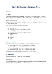
In the installation wizard, you can choose either Full or Custom installation. Custom mode<br />
will let you select optional components of the program:<br />
Figure 2.1<br />
Installation — customization by selecting optional components<br />
15
Introduction<br />
• <strong>Kerio</strong> Control Engine — core of the application.<br />
• VPN Support — proprietary VPN solution developed by <strong>Kerio</strong> Technologies (<strong>Kerio</strong> VPN ).<br />
• Administration Console — the <strong>Kerio</strong> Administration Console application (universal<br />
console for all server applications of <strong>Kerio</strong> Technologies) including <strong>Kerio</strong> Control<br />
administration tools.<br />
• Help files — this manual in the HTML Help format. For help files details, see <strong>Kerio</strong><br />
Administration Console — Help (available at http://www.kerio.com/firewall/manual).<br />
Go to chapter 2.9 for a detailed description of all <strong>Kerio</strong> Control components.<br />
description on the proprietary VPN solution, refer to chapter 23.<br />
For detailed<br />
Having completed this step, you can start the installation process. All files will be copied to the<br />
hard disk and all the necessary system settings will be performed. The initial wizard for basic<br />
<strong>Kerio</strong> Control configuration will be run automatically after your first login (see chapter 2.5).<br />
Under usual circumstances, reboot of the computer is not required after the installation<br />
(restart may be required if the installation program rewrites shared files which are currently<br />
in use). This will install the <strong>Kerio</strong> Control Engine low-level driver into the system kernel. <strong>Kerio</strong><br />
Control Engine and <strong>Kerio</strong> Control Engine Monitor will be automatically launched when the<br />
installation is complete. The engine runs as a service.<br />
Note:<br />
1. If you selected the Custom installation mode, the behavior of the installation program will<br />
be as follows:<br />
• all checked components will be installed or updated,<br />
• all checked components will not be installed or will be removed<br />
During an update, all components that are intended to remain must be ticked.<br />
2. The installation program does not allow to install the Administration Console separately.<br />
Installation of the Administration Console for the full remote administration requires<br />
a separate installation package (file kerio-control-admin*.exe).<br />
Protection of the installed product<br />
To provide the firewall with the highest security possible, it is necessary to ensure that<br />
undesirable (unauthorized) persons has no access to the critical files of the application,<br />
especially to configuration files. If the NTFS system is used, <strong>Kerio</strong> Control refreshes settings<br />
related to access rights to the directory (including all subdirectories) where the firewall is<br />
installed upon each startup. Only members of the Administrators group and local system<br />
account (SYSTEM) are assigned the full access (read/write rights), other users are not allowed<br />
access the directory.<br />
16
2.4 Installation - Windows<br />
Warning:<br />
If the FAT32 file system is used, it is not possible to protect <strong>Kerio</strong> Control in the above way.<br />
Thus, we strongly recommend to install <strong>Kerio</strong> Control only on NTFS disks.<br />
Conflicting Applications and System Services<br />
The <strong>Kerio</strong> Control installation program detects applications and system services that might<br />
conflict with the <strong>Kerio</strong> Control Engine.<br />
1. Windows Firewall’s system components 1 and Internet Connection Sharing.<br />
These components provide the same low-level functions as <strong>Kerio</strong> Control. If they are<br />
running concurrently with <strong>Kerio</strong> Control, the network communication would not be<br />
functioning correctly and <strong>Kerio</strong> Control might be unstable. Both components are run by<br />
the Windows Firewall / Internet Connection Sharing system service. 2 .<br />
Warning:<br />
To provide proper functionality of <strong>Kerio</strong> Control, it is necessary that the Internet<br />
Connection Firewall / Internet Connection Sharing detection is stopped and<br />
forbidden!<br />
2. Universal Plug and Play Device Host and SSDP Discovery Service<br />
The listed services support UPnP protocol (Universal Plug and Play) on Windows. However,<br />
these services collide with the UPnP support in <strong>Kerio</strong> Control (refer to chapter 18.2).<br />
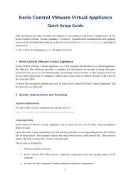
The <strong>Kerio</strong> Control installation includes a dialog where it is possible to disable colliding system<br />
services.<br />
By default, the <strong>Kerio</strong> Control installation disables all the colliding services listed. Under usual<br />
circumstances, it is not necessary to change these settings. Generally, the following rules are<br />
applied:<br />
• The Windows Firewall / Internet Connection Sharing (ICS) service should be disabled.<br />
Otherwise, <strong>Kerio</strong> Control will not work correctly. The option is a certain kind of<br />
warning which informs users that the service is running and that it should be disabled.<br />
• To enable support for the UPnP protocol in <strong>Kerio</strong> Control (see chapter 18.2), it is<br />
necessary to disable also services UPnP Device Host and SSDP Discovery Service.<br />
• It is not necessary to disable the services unless you need to use the UPnP in <strong>Kerio</strong><br />
Control.<br />
1 In Windows XP Service Pack 1 and older versions, the integrated firewall is called Internet Connection Firewall.<br />
2 In the older Windows versions listed above, the service is called Internet Connection Firewall / Internet Connection<br />
Sharing.<br />
17
Introduction<br />
Figure 2.2<br />
Disabling colliding system services during installation<br />
Note:<br />
1. Upon each startup, <strong>Kerio</strong> Control detects automatically whether the Windows Firewall /<br />
Internet Connection Sharing is running. If it is, WinRoute stops it and makes a record in<br />
the Warning log. This helps assure that the service will be enabled/started immediately<br />
after the <strong>Kerio</strong> Control installation.<br />
2. On Windows XP Service Pack 2, Windows Server 2003, Windows Vista, Windows Server 2008<br />
and Windows 7, <strong>Kerio</strong> Control registers in the Security Center automatically. This implies<br />
that the Security Center always indicates firewall status correctly and it does not display<br />
warnings informing that the system is not protected.<br />
2.5 Initial configuration wizard (Windows)<br />
Using this wizard you can define all basic <strong>Kerio</strong> Control parameters. It is started automatically<br />
by the installation program for Windows.<br />
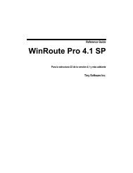
Setting of administration username and password<br />
Definition of the administration password is essential for the security of the firewall. Do not<br />
use the standard (blank) password, otherwise unauthorized users may be able to access the<br />
<strong>Kerio</strong> Control configuration.<br />
18
2.5 Initial configuration wizard (Windows)<br />
Figure 2.3<br />
Initial configuration — Setting of administration username and password<br />
Password and its confirmation must be entered in the dialog for account settings. Name Admin<br />
can be changed in the Username edit box.<br />
Note: If the installation is running as an upgrade, this step is skipped since the administrator<br />
account already exists.<br />
Remote Access<br />
Immediately after the first <strong>Kerio</strong> Control Engine startup all network traffic will be blocked<br />
(desirable traffic must be permitted by traffic rules — see chapter 7). If <strong>Kerio</strong> Control is<br />
installed remotely (i.e. using terminal access), communication with the remote client will be<br />
also interrupted immediately (<strong>Kerio</strong> Control must be configured locally).<br />
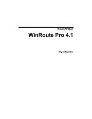
Within Step 2 of the configuration wizard, specify the IP address of the host from which the<br />
firewall will be controlled remotely to enable remote installation and administration (provided<br />
that the <strong>Kerio</strong> Control Engine is started). Thus <strong>Kerio</strong> Control will enable all traffic between the<br />
firewall and the remote host.<br />
Note: Skip this step if you install <strong>Kerio</strong> Control locally. Allowing full access from a point might<br />
endanger security.<br />
Enable remote access<br />
This option enables full access to the <strong>Kerio</strong> Control computer from a selected IP address<br />
Remote IP address<br />
IP address of the computer from where you will be connecting (e.g. terminal services<br />
client). This field must contain an IP address. A domain name is not allowed.<br />
19
Introduction<br />
Figure 2.4<br />
Initial configuration — Allowing remote administration<br />
Warning:<br />
The remote access rule is disabled automatically when <strong>Kerio</strong> Control is configured using the<br />
network policy wizard (see chapter 7.1).<br />
2.6 Upgrade and Uninstallation - Windows<br />
Upgrade<br />
Simply run the installation of a new version to upgrade WinRoute (i.e. to get a new release<br />
from the <strong>Kerio</strong> Web pages — http://www.kerio.com/).<br />
All windows of the <strong>Kerio</strong> Administration Console must be closed before the (un)installation is<br />
started. Components <strong>Kerio</strong> Control Engine and <strong>Kerio</strong> Control Engine Monitor will be stopped<br />
and closed automatically by the installation program.<br />
The installation program detects the directory with the former version and updates it by<br />
replacing appropriate files with the new ones automatically. License, all logs and user defined<br />
settings are kept safely.<br />
Note: This procedure applies to upgrades between versions of the same series (e.g. from 7.0.0<br />
to 7.0.1) or from a version of the previous series to a version of the subsequent series (e.g.<br />
from <strong>Kerio</strong> WinRoute Firewall 6.7.1 to <strong>Kerio</strong> Control 7.0.0). For case of upgrades from an older<br />
series version (e.g. 6.6.1), full compatibility of the configuration cannot be guaranteed and it<br />
is recommended to upgrade “step by step” (e.g. 6.6.1 → 6.7.1 → 7.0.0) or to uninstall the old<br />
version along with all files and then install the new version “from scratch”.<br />
20
2.6 Upgrade and Uninstallation - Windows<br />
Warning:<br />
Since 6.x, some configuration parameters have been changed in version for 7.0.0. Although<br />
updates are still performed automatically and seamlessly, it is necessary to mind the<br />
changes described above that take effect immediately upon installation of the new version.<br />
The following parameters are affected:<br />
• HTTP cache directory — newly, the firewall installation directory’s cache subfolder<br />
is always used, typically<br />
C:\Program Files\<strong>Kerio</strong>\WinRoute Firewall\cache.<br />
In case that the HTTP cache is located in a different directory, it can be moved<br />
(provided that the <strong>Kerio</strong> Control Engine service is not running). However, such<br />
measure can be rather disserviceable as the product update actually empties the<br />
cache which may often increase its effectivity.<br />
For details on HTTP cache, see chapter 9.5.<br />
• Supportive scripts for dial-up control — these scripts must always be saved in the<br />
firewall installation directory’s scripts subfolder, typically<br />
C:\Program Files\<strong>Kerio</strong>\WinRoute Firewall\scripts<br />
and they all need fixed names.<br />
If these scripts were used int he previous version of the product, it is necessary to<br />
move them to the directory with correct names used.<br />
For details on dial-up configuration, see chapter 6.2.<br />
• Log file names — fixed log file names are set now (alert.log, config.log,<br />
debug.log, etc.).<br />
The same path used for saving log files is kept — logs are save under the logs<br />
subdirectory under the firewall installation directory, typically<br />
C:\Program Files\<strong>Kerio</strong>\WinRoute Firewall\logs<br />
If log file names has been changed, the original files are kept and new logs are<br />
recorded in files with corresponding names.<br />
• Log type (Facility) and its Severity for external logging on the Syslog server — fixed<br />
facility and severity values of individual logs of <strong>Kerio</strong> Control are now set. This is<br />
a fact to bear in mind while viewing firewall logs on the Syslog server.<br />
For details on log settings, see chapter 22.1.<br />
After update, it is recommended to check Warning log carefully (see chapter 22.13).<br />
Update Checker<br />
<strong>Kerio</strong> Control enables automatic checks for new versions of the product at the <strong>Kerio</strong> Technologies<br />
website. Whenever a new version is detected, its download and installation will be offered<br />
automatically.<br />
21
Introduction<br />
For details, refer to chapter 17.3.<br />
Uninstallation<br />
Before uninstalling the product, it is recommended to close all <strong>Kerio</strong> Control components. The<br />
Add/Remove Programs option in the Control Panel launches the uninstallation process. All<br />
files under the <strong>Kerio</strong> Control directory can be optionally deleted.<br />
(the typical path is C:\Program Files\<strong>Kerio</strong>\WinRoute Firewall)<br />
— configuration files, SSL certificates, license key, logs, etc.<br />
Figure 2.5<br />
Uninstallation — asking user whether files created in <strong>Kerio</strong> Control should be deleted<br />
Keeping these files may be helpful for copying of the configuration to another host or if it is<br />
not sure whether the SSL certificates were issued by a trustworthy certification authority.<br />
During uninstallation, the <strong>Kerio</strong> Control installation program automatically refreshes the<br />
original status of the Windows Firewall / Internet Connection Sharing, Universal Plug and Play<br />
Device Host) and SSDP Discovery Service system services.<br />
2.7 Installation - <strong>Software</strong> Appliance and VMware Virtual Appliance<br />
<strong>Kerio</strong> Control in the software appliance edition is distributed:<br />
• as an ISO of the installation CD which is used to install the system and then install the<br />
firewall either on a physical or virtual computer (<strong>Software</strong> Appliance),<br />
• as a virtual appliance for VMware (VMware Virtual Appliance).<br />
Standalone <strong>Kerio</strong> Control installation package for installation on previously installed Linux is<br />
not available.<br />
22
2.7 Installation - <strong>Software</strong> Appliance and VMware Virtual Appliance<br />
<strong>Software</strong> Appliance / VMware Virtual Appliance installation process consists of the following<br />
simple steps:<br />
Start of the installation<br />
<strong>Software</strong> Appliance<br />
ISO image of the installation CD can be burned on a physical CD and then the CD can<br />
be used for installation of the system on the target computer (either physical or virtual).<br />
In case of virtual computers, the ISO image can be also connected as a virtual CD ROM,<br />
without the need to burn the installation ISO file on a CD.<br />
Note: <strong>Kerio</strong> Control <strong>Software</strong> Appliance cannot be installed on a computer with another<br />
operating system. Existing operating system on the target disk will be removed within<br />
the installation.<br />
VMware Virtual Appliance<br />
Supported VMware hypervisor versions:<br />
• Workstation 6.5 and 7.0<br />
• Server 2.0<br />
• Fusion 2.0 and 3.0<br />
• Player 2.5 and 3.0<br />
• ESX 3.5 and 4.0<br />
• ESXi 3.5 and 4.0<br />
Use an installation package in accordance with the type of your VMware product (see<br />
above):<br />
• In case of products VMware Server, Workstation and Fusion, download the<br />
compressed VMX distribution file (*.zip), unpack it and open it in the your<br />
VMware product.<br />
• You can import a virtual appliance directly to VMware ESX/ESXi from the URL of<br />
the OVF file — for example:<br />
http://download.kerio.com/dwn/control/<br />
kerio-control-appliance-7.0.0-1234-linux.ovf<br />
VMware ESX/ESXi automatically downloads the OVF configuration file and<br />
a corresponding disk image (.vmdk).<br />
If you import virtual appliance in the OVF format, bear in mind the following specifics:<br />
• In the imported virtual appliance, time synchronization between the host and<br />
the virtual appliance is disabled. However, <strong>Kerio</strong> Control features a proprietary<br />
mechanism for synchronization of time with public Internet time servers.<br />
Therefore, it is not necessary to enable synchronization with the host.<br />
• Tasks for shutdown or restart of the virtual machine will be set to default values<br />
after the import. These values can be set to “hard” shutdown or “hard” reset.<br />
However, this may cause loss of data on the virtual appliance. <strong>Kerio</strong> Control<br />
VMware Virtual Appliance supports so called Soft Power Operations which<br />
23
Introduction<br />
allow to shutdown or restart hosted operating system properly. Therefore, it is<br />
recommended to set shutdown or restart of the hosted operating system as the<br />
value.<br />
The following steps are identical both for <strong>Software</strong> Appliance and Virtual Appliance.<br />
Language selection<br />
The selected language will be used both for <strong>Kerio</strong> Control installation and for the firewall’s<br />
console (see chapter 2.11).<br />
Selection of target hard disk<br />
If the installation program detects more hard disks in the computer, then it is necessary to<br />
select a disk for <strong>Kerio</strong> Control installation. Content of the selected disk will be completely<br />
removed before <strong>Kerio</strong> Control installation, while other disk are not affected by the installation.<br />
If there is an only hard disk detected on the computer, the installer continues with the<br />
following step automatically. If no hard disk is found, the installation is closed. Such error is<br />
often caused by an unsupported hard disk type or hardware defect.<br />
Selection of network interface for the local network and access to administration<br />
The installer lists all detected network interfaces of the firewall. Select an interface which is<br />
connected to the local (trustworthy) network which the firewall will be remotely administered<br />
from.<br />
In the field, a computer may have multiple interfaces of the same type and it is therefore not<br />
easy to recognize which interface is connected to the local network and which to the Internet.<br />
To a certain extent, hardware addresses of the adapters can be a clue or you can experiment<br />
— select an interface, complete the installation and try to connect to the administration. If the<br />
connection fails, use option Network Configuration in the main menu of the firewall’s console<br />
to change the settings (see chapter 2.11).<br />
There can also arise another issue — that the program does not detect some or any network<br />
adapters. In such case, it is recommended to use another type of the physical or virtual (if the<br />
virtual computer allows this) adapter or install <strong>Kerio</strong> Control <strong>Software</strong> Appliance on another<br />
type of virtual machine. If such issue arises, it is highly recommended to consult the problem<br />
with the <strong>Kerio</strong> Technologies technical support (see chapter 26).<br />
Provided that no network adapter can be detected, it is not possible to continue installing<br />
<strong>Kerio</strong> Control.<br />
24
2.7 Installation - <strong>Software</strong> Appliance and VMware Virtual Appliance<br />
Setting of the local interface’s IP address<br />
It is now necessary to define IP address and subnet mask for the selected local network<br />
interface. These parameters can be defined automatically by using information from a DHCP<br />
server or manually.<br />
For the following reasons, it is recommended to set local interface parameters manually:<br />
• Automatically assigned IP address can change which may cause problems with<br />
connection to the firewall administration (although the IP address can be reserved<br />
on the DHCP server, this may bring other problems).<br />
• In most cases <strong>Kerio</strong> Control will be probably used itself as a DHCP server for local<br />
hosts (workstations).<br />
Admin password<br />
The installation requires specification of the password for the account Admin (the account of<br />
the main administrator of the firewall). Username Admin with this password are then used for<br />
access:<br />
• to the firewall’s console (see chapter 2.11),<br />
• to the remote administration of the firewall via the web administration interface (see<br />
chapter 3),<br />
• to the remote administration of the firewall via the <strong>Kerio</strong> Administration Console (see<br />
chapter 3).<br />
Remember this password or save it in a secured location and keep it from anyone else!<br />
Time zone, date and time settings<br />
Many <strong>Kerio</strong> Control features (user authentication, logs, statistics, etc.) require correct setting<br />
of date, time and time zone on the firewall. Select your time zone and in the next page check<br />
(and change, if necessary) date and time settings.<br />
Completing the installation<br />
Once all these parameters are set, the <strong>Kerio</strong> Control Engine service (daemon) is started.<br />
While the firewall is running, the firewall’s console will display information about<br />
remote administration options and change of some basic configuration parameters — see<br />
chapter 2.11.<br />
25
Introduction<br />
2.8 Upgrade - <strong>Software</strong> Appliance / VMware Virtual Appliance<br />
<strong>Kerio</strong> Control can be upgraded by the following two methods:<br />
• by starting the system from the installation CD (or a mounted ISO) of the new version.<br />
The installation process is identical with the process of a new installation with an the<br />
only exception that at the start the installer asks you whether to execute an upgrade<br />
(any existing data will be kept) or a new installation (all configuration files, statistics,<br />
logs, etc will be removed). For details, see chapter 2.7.<br />
• by the <strong>Kerio</strong> Administration Console update checker. For details, refer to chapter 17.3<br />
Warning:<br />
Since 6.7.1, some configuration parameters have been changed for version 7.0.0. Although<br />
updates are still performed automatically and seamlessly, it is necessary to mind the<br />
changes described above that take effect immediately upon installation of the new version.<br />
The following parameters are affected:<br />
• Log file names — fixed log file names are set now (alert.log, config.log,<br />
debug.log, etc.).<br />
The path for saving the log files is kept unchanged — logs are saved under<br />
/opt/kerio/winroute/logs<br />
If log file names has been changed, the original files are kept and new logs are<br />
recorded in files with corresponding names.<br />
• Log type (Facility) and its Severity for external logging on the Syslog server — fixed<br />
facility and severity values of individual logs of <strong>Kerio</strong> Control are now set. This is<br />
a fact to bear in mind while viewing firewall logs on the Syslog server.<br />
For details on log settings, see chapter 22.1.<br />
After update, it is recommended to check Warning log carefully (see chapter 22.13).<br />
2.9 <strong>Kerio</strong> Control components<br />
<strong>Kerio</strong> Control consists of these components:<br />
<strong>Kerio</strong> Control Engine<br />
The core of the program that executes all services and functions. It is running as a service<br />
in the operating system (the service is called <strong>Kerio</strong> Control and it is run automatically<br />
within the system account by default).<br />
<strong>Kerio</strong> Control Engine Monitor (Windows only)<br />
Allows viewing and modification of the Engine’s status (stopped / running) and setting<br />
of start-up preferences (i.e. whether Engine and Monitor should be run automatically at<br />
system start-up). It also provides easy access to the Administration Console. For details,<br />
refer to chapter 2.10.<br />
26
2.10 <strong>Kerio</strong> Control Engine Monitor (Windows)<br />
Note: <strong>Kerio</strong> Control Engine is independent from the <strong>Kerio</strong> Control Engine Monitor. The<br />
Engine can be running even if there is no icon in the system tray.<br />
<strong>Kerio</strong> Administration Console (Windows only)<br />
It is a versatile console for full local or remote administration of <strong>Kerio</strong> Technologies<br />
server products. For successful connection to an application you need a plug-in with<br />
an appropriate interface.<br />
<strong>Kerio</strong> Administration Console is installed on Windows hand-in-hand with the appropriate<br />
module during the installation of <strong>Kerio</strong> Control. The separate installation package <strong>Kerio</strong><br />
Administration Console for <strong>Kerio</strong> Control is available for remote administration from<br />
another host. The <strong>Kerio</strong> Administration Console is available for Windows only, but it can<br />
be used for administration of both <strong>Kerio</strong> Control installed on Windows and <strong>Kerio</strong> Control<br />
<strong>Software</strong> Appliance / VMware Virtual Appliance.<br />
Detailed guidance for <strong>Kerio</strong> Administration Console is provided in <strong>Kerio</strong> Administration<br />
Console — Help (http://www.kerio.com/firewall/manual).<br />
The firewall’s console (<strong>Software</strong> Appliance / VMware Virtual Appliance only)<br />
The firewall’s console is a simple interface permanently running on the <strong>Kerio</strong> Control<br />
host. It allows to set basic parameters of the operating system and the firewall for cases<br />
when it is not possible to administer it remotely via the Administration web interface or<br />
the <strong>Kerio</strong> Administration Console.<br />
2.10 <strong>Kerio</strong> Control Engine Monitor (Windows)<br />
<strong>Kerio</strong> Control Engine Monitor is a standalone utility used to control and monitor the <strong>Kerio</strong><br />
Control Engine status. The icon of this component is displayed on the toolbar.<br />
Figure 2.6<br />
<strong>Kerio</strong> Control Engine Monitor icon in the Notification Area<br />
If <strong>Kerio</strong> Control Engine is stopped, a white crossed red spot appears on the icon. Starting or<br />
stopping the service can take several seconds. For this time the icon gets grey and is inactive.<br />
On Windows, left double-clicking on this icon runs the <strong>Kerio</strong> Administration Console (described<br />
later). Use the right mouse button to open the following menu:<br />
Start-up Preferences<br />
With these options <strong>Kerio</strong> Control Engine and/or Engine Monitor applications can be set<br />
to be launched automatically when the operating system is started. Both options are<br />
enabled by default.<br />
Administration<br />
Runs <strong>Kerio</strong> Administration Console (equal to double-clicking on the Engine Monitor icon).<br />
27
Introduction<br />
Figure 2.7<br />
<strong>Kerio</strong> Control Engine Monitor menu<br />
Internet Usage Statistics<br />
Opens Internet Usage Statistics in the default browser. For details, see chapter 21.<br />
Start/Stop <strong>Kerio</strong> Control<br />
Switches between the Start and Stop modes. The text displays the current mode status.<br />
Exit Engine Monitor<br />
An option to exit Engine Monitor. This option does not stop the <strong>Kerio</strong> Control Engine. The<br />
user is informed about this fact by a warning window.<br />
Note:<br />
1. If a limited version of <strong>Kerio</strong> Control is used (e.g. trial version), a notification is displayed<br />
7 days before its expiration. This information is displayed until the expiration.<br />
2. <strong>Kerio</strong> Control Engine Monitor is available in English only.<br />
2.11 The firewall’s console (<strong>Software</strong> Appliance / VMware Virtual Appliance)<br />
On the console of the computer where <strong>Kerio</strong> Control <strong>Software</strong> Appliance / VMware Virtual Appliance<br />
is running, information about the firewall remote administration options is displayed.<br />
Upon authenticating by the administration password (see above), this console allows to change<br />
some basic settings, restore default settings after installation and shut down or restart the<br />
computer.<br />
By default, the console shows only information about URL or IP address which can be used<br />
for firewall administration via the firewall’s web administration interface or the <strong>Kerio</strong> Administration<br />
Console. To access configuration options, authentication with the Admin password is<br />
required (Admin is the main firewall administrator’s account). If idle for some time, the user<br />
gets logged out automatically and the welcome page of the console showing details on the<br />
firewall’s remote administration is displayed again.<br />
The firewall’s console provides the following configuration options:<br />
Network interface configurations<br />
This option allows to show or/and edit parameters of individual network interfaces of the<br />
firewall. Each interface allows definition of automatic configuration via DHCP or manual<br />
configuration of IP address, subnet mask and default gateway.<br />
28
2.11 The firewall’s console (<strong>Software</strong> Appliance / VMware Virtual Appliance)<br />
Note: No default gateway should be set on interfaces connected to the local network,<br />
otherwise this firewall cannot be used as agateway for the Internet access.<br />
Remote administration policy settings<br />
When you change the firewall’s traffic policy (see chapter 7) via the web administration<br />
interface or the <strong>Kerio</strong> Administration Console, you may happen to block access to the<br />
remote administration accidentally.<br />
If you are sure that the firewall’s network interfaces are configured correctly and despite<br />
of that it is not possible to access the remote administration, you can use the Remote<br />
Administration option to change the traffic policy so that the rules do not block remote<br />
administration on any interface.<br />
Upon saving changes in traffic rules, the <strong>Kerio</strong> Control Engine service will be restarted<br />
automatically.<br />
I the field, unblocking of the remote administration means that a rule will be added to the<br />
top of the traffic policy table that would allow access Control Admin (connection with the<br />
<strong>Kerio</strong> Administration Console), <strong>Kerio</strong> Control WebAdmin and <strong>Kerio</strong> Control WebAdmin-SSL<br />
(secured web interface of the firewall) services from any computer.<br />
Shutting down / restarting the firewall<br />
If you need to shut your computer down or reboot it, these options provide secure closure<br />
of the <strong>Kerio</strong> Control Engine and shutdown of the firewall’s operating system.<br />
Restoring default configuration<br />
This option restores the default firewall settings as installed from the installation CD<br />
or upon the first startup of the VMware virtual host. All configuration files and data<br />
(logs, statistics, etc.) will be removed and it will then be necessary to execute the initial<br />
configuration of the firewall again as if a new installation (see chapter 2.7).<br />
Restoring the default configuration can be helpful if the firewall’s configuration is<br />
accidentally damaged that much that it cannot be corrected by any other means.<br />
29
Chapter 3<br />
<strong>Kerio</strong> Control administration<br />
For <strong>Kerio</strong> Control configuration, two tools are available:<br />
<strong>Kerio</strong> Control Administration web interface<br />
The Administration interface allows both remote and local administration of the firewall<br />
via a common web browser. In the current version of <strong>Kerio</strong> Control, the Administration<br />
interface allows configuration of the most of basic options and parameters of the firewall:<br />
• network adapters,<br />
• traffic rules — manual configuration only; the Traffic Policy Wizard (see<br />
chapter 7.1) is not available,<br />
• intrusion prevention system,<br />
• MAC address filtering,<br />
• additional security options (Anti-Spoofing, connections count limits, UPnP<br />
support)<br />
• DHCP server (including automatic configuration),<br />
• HTTP and FTP filtering rules,<br />
• user accounts, groups, user authentication and domain mapping,<br />
• IP groups, URL groups, time ranges and network services,<br />
• logs.<br />
On the other hand, some of the recently added features are available only in the web<br />
interface:<br />
• exporting and importing configuration,<br />
• automatic configuration of IP scopes on the DHCP server.<br />
<strong>Kerio</strong> Administration Console<br />
<strong>Kerio</strong> Administration Console (referred to as the Administration Console in this document)<br />
is an application used for administration of all <strong>Kerio</strong> Technologies’ server products. All<br />
<strong>Kerio</strong> Control parameters can be configured here.<br />
Using this program you can access the firewall either locally (from the <strong>Kerio</strong> Control<br />
host) or remotely (from another host). Traffic between Administration Console and <strong>Kerio</strong><br />
Control Engine is encrypted. This protects you from tapping and misuse.<br />
<strong>Kerio</strong> Administration Console is installed on Windows hand-in-hand with it during the<br />
installation of <strong>Kerio</strong> Control.<br />
The separate installation package <strong>Kerio</strong> Administration Console for <strong>Kerio</strong> Control is<br />
available for remote administration from another host. The <strong>Kerio</strong> Administration Console<br />
is available for Windows only, but it can be used for administration of both <strong>Kerio</strong> Control<br />
installed on Windows and <strong>Kerio</strong> Control <strong>Software</strong> Appliance / VMware Virtual Appliance.<br />
30
3.1 <strong>Kerio</strong> Control Administration web interface<br />
Detailed guidelines for the Administration Console are provided under <strong>Kerio</strong> Administration<br />
Console — Help (to view these guidelines, use option Help → Contents<br />
in the main Administration Console window, or you can download it from<br />
http://www.kerio.com/firewall/manual).<br />
The following chapters of this manual describe individual sections of the Administration Console<br />
and the web administration interface.<br />
Note:<br />
1. The Administration web interface and the Administration Console for <strong>Kerio</strong> Control are<br />
available in 16 localization versions. The Administration interface allows language<br />
selection by simple switching of the flag located in the top right corner of the window<br />
or by following the browser language preferences. The Administration Console allows<br />
language settings in the Tools menu of the login dialog box.<br />
2. Upon the first login to the Administration Console after a successful <strong>Kerio</strong> Control<br />
installation, the traffic rules wizard is run so that the initial <strong>Kerio</strong> Control configuration<br />
can be performed. For a detailed description on this wizard, please refer to chapter 7.17.1.<br />
The wizard is not available in the current version of the Administration interface.<br />
Therefore it is recommended to use the Administration Console for the initial configuration<br />
of <strong>Kerio</strong> Control (immediately upon the installation).<br />
3.1 <strong>Kerio</strong> Control Administration web interface<br />
The <strong>Kerio</strong> Control Administration interface is available at https://server:4081/admin<br />
(server stands for the firewall name or IP address and 4081 for the port of its web interface).<br />
HTTPS traffic between the client and the <strong>Kerio</strong> Control Engine is encrypted. This protects the<br />
communication from tapping and misuse. It is recommended to use the unsecured version<br />
of the Administration (the HTTP protocol on port 4080) only for local administration of <strong>Kerio</strong><br />
Control (i.e. administration from the computer where it is installed).<br />
Upon a successful logon to the Administration web interface, the main window consisting of<br />
two sections is displayed:<br />
• The left column contains the tree view of sections. For better transparency it is<br />
possible to hide or show individual parts of the tree (upon logon, the full tree is<br />
shown).<br />
• The right column lists contents of the section previously selected in the left column.<br />
In most cases, configuration changes in individual sections are performed only at the client’s<br />
side (i.e. in the web browser) and get applied on the configuration file upon clicking on the<br />
Apply button. Therefore, it is possible to use the Cancel button to recover the former settings.<br />
31
<strong>Kerio</strong> Control administration<br />
Figure 3.1<br />
Main window of the <strong>Kerio</strong> Control Administration interface<br />
3.2 Administration Console - the main window<br />
After the user has been successfully logged in to the <strong>Kerio</strong> Control Engine by the <strong>Kerio</strong> Administration<br />
Console, the main window of the <strong>Kerio</strong> Control administration plugin is displayed<br />
(further called the “administration window”). This window is divided into two parts:<br />
• The left column contains the tree view of sections. The individual sections of the<br />
tree can be expanded and collapsed for easier navigation. Administration Console<br />
remembers the current tree settings and uses them upon the next login.<br />
• In the right part of the window, the contents of the section selected in the left column<br />
is displayed (or a list of sections in the selected group).<br />
In most cases, configuration changes in individual sections are performed only at the client’s<br />
side and get applied on the configuration file upon clicking on the Apply button. Therefore, it<br />
is possible to use the Cancel button to recover the former settings.<br />
32
3.2 Administration Console - the main window<br />
Figure 3.2<br />
The main window of Administration Console for <strong>Kerio</strong> Control<br />
Administration Window — Main menu<br />
The main menu provides the following options:<br />
File<br />
• Reconnect — using this option, the connection to the <strong>Kerio</strong> Control Engine after<br />
a connection drop-out (e.g. after the Engine restart or network failure) can be<br />
restored.<br />
• New connection — opens the main window of the Administration Console. Use<br />
a bookmark or the login dialog to connect to a server.<br />
This option can be useful when the console will be used for administration of<br />
multiple server applications (e.g. <strong>Kerio</strong> Control at multiple servers). For details,<br />
refer to the Help section in the Administration Console manual.<br />
Note: The New Connection option opens the same dialog as running the Administration<br />
Console from the Start menu.<br />
• Quit — this option terminates the session (users are logged out of the server and<br />
the administration window is closed). The same effect can be obtained by clicking<br />
the little cross in the upper right corner of the window or pressing Alt+F4 or<br />
Ctrl+Q.<br />
The Edit menu (on the welcome page only)<br />
Options under Edit are related to product registration and licensing. The options available<br />
in the menu depend on the registration status (for example, if the product is registered<br />
as a trial version, it is possible to use options of registration of a purchased license or<br />
a change of registration data).<br />
33
<strong>Kerio</strong> Control administration<br />
• Copy license number to clipboard — copies the license number (the ID licence<br />
item) to the clipboard. This may be helpful e.g. when ordering an upgrade or<br />
subscription, where the number of the base license is required, or when sending<br />
an issue to the <strong>Kerio</strong> Technologies technical support.<br />
• Register trial version — registration of the product’s trial version.<br />
• Register product — registration of a product with a purchased license number.<br />
• Install license — use this option to import your license key file (for details, see<br />
chapter 4.5).<br />
Help menu<br />
• Show Server’s Identity — this option provides information about the firewall<br />
which the Administration Console is currently connected to (name or IP address<br />
of the server, port and SSL-certificate fingerprint). This information can be used<br />
for authentication of the firewall when connecting to the administration from<br />
another host (see <strong>Kerio</strong> Administration Console — Help).<br />
• Administrator’s guide — this option displays the administrator’s guide in HTML<br />
Help format. For details about help files, see <strong>Kerio</strong> Administration Console — Help<br />
manual.<br />
• About — this option provides information about the version of the <strong>Kerio</strong> Control<br />
and a link to the <strong>Kerio</strong> Technologies website.<br />
Status bar<br />
The status bar at the bottom of the administration window displays the following information<br />
(from left to right):<br />
Figure 3.3<br />
Administration Console status bar<br />
• The section of the administration window currently selected in the left column. This<br />
information facilitates navigation in the administration window when any part of the<br />
section tree is not visible (e.g. when a lower screen resolution is selected).<br />
• Name or IP address of the server and port of the server application (<strong>Kerio</strong> Control uses<br />
port 44333).<br />
• Name of the user logged in as administrator.<br />
• Current state of the Administration Console: Ready (waiting for user’s response), Loading<br />
(retrieving data from the server) or Saving (saving changes to the server).<br />
34
3.3 Administration Console - view preferences<br />
Detection of the <strong>Kerio</strong> Control Engine connection failure<br />
Administration Console is able to detect the connection failure automatically. The failure is<br />
usually detected upon an attempt to read/write the data from/to the server (i.e. when the Apply<br />
button is pressed or when a user switches to a different section of Administration Console).<br />
In such case, a connection failure dialog box appears where the connection can be restored.<br />
After you remove the cause of the connection failure, the connection can be restored. Administration<br />
Console provides the following options:<br />
• Apply & Reconnect — connection to the server will be recovered and all changes done<br />
in the current section of the Administration Console before the disconnection will be<br />
saved,<br />
• Reconnect — connection to the server will be recovered without saving any changes<br />
performed in the particular section of the console before the disconnection.<br />
If the reconnection attempt fails, only the error message is shown. You can then try to<br />
reconnect using the File → Restore connection option from the main menu, or close the window<br />
and restore the connection using the standard procedure.<br />
Note: After a connection failure, the Administration interface is redirected and opened at the<br />
login page automatically. Any unsaved changes will get lost.<br />
3.3 Administration Console - view preferences<br />
Many sections of the Administration Console are in table form where each line represents<br />
one record (e.g. detailed information about user, information about interface, etc.) and the<br />
columns consist of individual entries for these records (e.g. name of server, MAC address, IP<br />
address, etc.).<br />
The firewall administrators can define — according to their liking — the way how the<br />
information in individual sections will be displayed. When you right-click each of the above<br />
sections, a pop-up menu with Modify columns option is displayed. This entry opens a dialog<br />
window where users can select which columns will be displayed/hidden.<br />
This dialog offers a list of all columns available for a corresponding view. Use checking boxes<br />
on the left to enable/disable displaying of a corresponding column. You can also click the<br />
Show all button to display all columns. Clicking on the Default button will restore default<br />
settings (for better reference, only columns providing the most important information are<br />
displayed by default).<br />
The arrow buttons move the selected column up and down within the list. This allows the<br />
administrator to define the order the columns will be displayed.<br />
The order of the columns can also be adjusted in the window view. Left-click on the column<br />
name, hold down the mouse button and move the column to the desired location.<br />
35
<strong>Kerio</strong> Control administration<br />
Figure 3.4<br />
Column customization in Interfaces<br />
Note:<br />
Move the dividing lines between the column headers to modify the width of the<br />
individual columns.<br />
36
Chapter 4<br />
License and Registration<br />
A valid license is required for usage of <strong>Kerio</strong> Control after 30-day trial period. Technically, the<br />
product works as this:<br />
• Immediately upon installation, the product works as a 30-day trial version. All features<br />
and options of the product are available except the <strong>Kerio</strong> Web Filter module and update<br />
of intrusion prevention system rules.<br />
• Trial version can be registered for free. Registered trial version users can use technical<br />
support for the product during the trial period. Registered users can also test the<br />
<strong>Kerio</strong> Web Filter module and their intrusion prevention system rules are updated<br />
automatically. Registration does not prolong the trial period.<br />
• Upon purchase of a license, it is necessary to register the product using the<br />
corresponding license key. Upon a successful registration, the product will be fully<br />
available according to the particular license policy (for details, see chapter 4.1).<br />
There is actually no difference between the trial and full version of <strong>Kerio</strong> Control except being<br />
or not being registered with a valid license. This gives each customer an opportunity to install<br />
and test the product in a particular environment during the trial period. Then, once the<br />
product is purchased, the customer can simply register the installed version by the purchased<br />
license number (see chapter 4.4). This means that it is not necessary to uninstall the trial<br />
version and reinstall the product.<br />
If the 30-day trial has already expired, <strong>Kerio</strong> Control stops working — the <strong>Kerio</strong> Control<br />
Engine system service gets stopped automatically. Upon registration with a valid license<br />
number (received as a response to purchase of the product), <strong>Kerio</strong> Control is available with<br />
full functionality.<br />
Note: Registration of <strong>Kerio</strong> Control generates a so called license key (the license.key file<br />
— see chapter 25.1). If your license key gets lost for any reason (e.g. after the hard drive<br />
breakdown or by an accidental removal, etc.), you can simply use the basic product’s purchase<br />
number to recover the license. The same method can be used also for change of the firewall’s<br />
operating system (Windows / <strong>Software</strong> Appliance / VMware Virtual Appliance) — the license<br />
keys cannot be used across different operating systems. If the license number gets lost,<br />
contact the <strong>Kerio</strong> Technologies sales department.<br />
37
License and Registration<br />
4.1 License types (optional components)<br />
<strong>Kerio</strong> Control can optionally include the following components: Sophos antivirus (refer to<br />
chapter 14) or/and the <strong>Kerio</strong> Web Filter module for web pages rating (see chapter 13.3). These<br />
components are licensed individually.<br />
License keys consist of the following information:<br />
<strong>Kerio</strong> Control license<br />
<strong>Kerio</strong> Control basic license Its validity is defined by the two following factors:<br />
• Update right expiration date — specifies the date by which <strong>Kerio</strong> Control can<br />
be updated for free. When this date expires, <strong>Kerio</strong> Control keeps functioning,<br />
however, it cannot be updated. The time for updates can be extended by<br />
purchasing a subscription.<br />
• Product expiration — by this date <strong>Kerio</strong> Control stops working — the <strong>Kerio</strong> Control<br />
Engine service gets stopped automatically.<br />
In this case, you need to register a valid license immediately or uninstall <strong>Kerio</strong><br />
Control. It is possible to run <strong>Kerio</strong> Control for purpose of registering. However,<br />
if a valid license is not installed in 10 minutes, the service is stopped again.<br />
Sophos antivirus license<br />
This license is defined by the two following dates:<br />
• update right expiration date (independent of <strong>Kerio</strong> Control) — when this date<br />
expires, the antivirus keeps functioning, however, neither its virus database nor<br />
the antivirus can be updated yet.<br />
• plug-in expiration date— specifies the date by which the Sophos antivirus stops<br />
functioning and cannot be used anymore.<br />
Warning:<br />
Owing to persistent incidence of new virus infections we recommend you to use<br />
always the most recent antivirus versions.<br />
<strong>Kerio</strong> Web Filter subscriptions<br />
<strong>Kerio</strong> Web Filter module is provided as a service. License is defined only by an expiration<br />
date which specifies when this module will be blocked.<br />
Note: Refer to the <strong>Kerio</strong> Technologies website (http://www.kerio.com/) to get up-to-date<br />
information about individual licenses, subscription extensions, etc.<br />
4.2 Deciding on a number of users (licenses)<br />
<strong>Kerio</strong> Control 7 introduces a new system of Internet access monitoring, better corresponding<br />
to the product’s licensing and usage policy. <strong>Kerio</strong> Technologies licenses this software as<br />
a server with the Admin account and 5 user accounts in the basic license. Users can be added<br />
in packages of five users.<br />
38
4.3 License information<br />
User is defined as a person who is permitted to connect to <strong>Kerio</strong> Control and its services. Each<br />
user can connect from up to five different devices represented by IP addresses, including VPN<br />
clients.<br />
If any user tries to connect from more than five devices at a time, another user license is used<br />
for this purpose. Although the product formerly did not limit number of connected users, it<br />
used to consider each IP address connected to the server as one user which might have caused<br />
situations where one user used up available licenses even by connecting from two device at<br />
a time.<br />
Warning:<br />
<strong>Kerio</strong> Control does not limit number of defined user accounts (see chapter 16). However, if<br />
the maximal number of currently authenticated users is reached, no other user can connect.<br />
4.3 License information<br />
The license information can be displayed by selecting <strong>Kerio</strong> Control (the first item in the<br />
tree in the left part of the Administration Console dialog window — this section is displayed<br />
automatically whenever the <strong>Kerio</strong> Control administration is entered).<br />
Figure 4.1<br />
Administration Console welcome page providing license information<br />
39
License and Registration<br />
Product<br />
Product name (<strong>Kerio</strong> Control).<br />
Copyright<br />
Copyright information.<br />
Homepage<br />
Link to the <strong>Kerio</strong> Control homepage (information on pricing, new versions, etc.). Click on<br />
the link to open the homepage in your default browser.<br />
Operational system<br />
Name of the operating system on which the <strong>Kerio</strong> Control Engine service is running.<br />
This is an informative item only — the purchased license can be used for any supported<br />
operating system.<br />
License ID<br />
License number or a special license name.<br />
Subscription expiration date<br />
Date until when the product can be upgraded for free.<br />
Product expiration date<br />
Date when the product expires and stops functioning (only for trial versions or special<br />
license types).<br />
Number of users<br />
Maximal number of users authenticated at the firewall at a time (for details, see<br />
chapter 4.2).<br />
Company<br />
Name of the company (or a person) to which the product is registered.<br />
Depending on the current license, links are displayed at the bottom of the image:<br />
1. For unregistered versions:<br />
• Become a registered trial user — registration of the trial version. This type of<br />
registration is tentative and it is not obligatory. The registration provides users<br />
free technical support for the entire trial period.<br />
• Register product with a purchased license number — registration of a purchased<br />
product.<br />
Once purchased, the product must be registered. Otherwise, it will keep behaving<br />
as a trial version!<br />
2. For registered versions:<br />
• Update registration info — this link can be used to update information about the<br />
person/company to which the product is registered and/or to add subscription<br />
license numbers or add-on licenses (add users).<br />
40
4.4 Registration of the product in the Administration Console<br />
In any case, the registration wizard will be started where basic data are required and additional<br />
data can also be defined. For detailed information on the wizard, refer to chapter 4.4.<br />
If the update checker is enabled (refer to chapter 17.3), the A new version is available, click<br />
here for details... notice is displayed whenever a new version is available. Click on the link to<br />
open the dialog where the new version can be downloaded and the installation can be started<br />
(for details, see chapter 17.3).<br />
Note: Right-clicking in the main page of the Administration Console opens a context pop-up<br />
menu with the same options as are provided in the Edit menu in the main toolbar of the<br />
administration window (see chapter 3.2).<br />
4.4 Registration of the product in the Administration Console<br />
<strong>Kerio</strong> Control registration, change of registration details, adding of add-on licenses and<br />
subscription updates can be done in the Administration Console by clicking on a corresponding<br />
link on the welcome page (see chapter 4.3) or by using a corresponding option in the Edit menu<br />
in the main menu for the administration window (see chapter 3.2).<br />
Registration of the trial version<br />
By registrating the trial version, users get free email and telephonic technical support for<br />
the entire trial period. In return, <strong>Kerio</strong> Technologies gets valuable feedback from these users.<br />
Registration of the trial version is not obligatory. However, it is recommended since it provides<br />
certain benefits. Such a registration does not oblige users to purchase the product.<br />
Clicking on Become a registered trial user launches the registration wizard.<br />
1. On the first page of the wizard, read the security code displayed in the picture and type<br />
it to the text field (this protects the registration server from misuse). The security code is<br />
not case-sensitive.<br />
Figure 4.2<br />
Trial version registration — security code<br />
41
License and Registration<br />
2. On the second page, enter information about the trial version user (person, company). It is<br />
also necessary that the user accepts the Privacy Policy Terms. Otherwise, the information<br />
cannot be stored in the <strong>Kerio</strong> Technologies database.<br />
Use the E-mail address textfield to enter a valid email address. It is recommended to use<br />
the address of the user who is performing the registration. At this address, confirmation<br />
of the registration will be demanded when the registration is completed.<br />
Figure 4.3<br />
Trial version registration — user information<br />
3. Page three includes optional information. It is not obligatory to answer these questions,<br />
however, the answers help <strong>Kerio</strong> Technologies accommodate demands of as many<br />
customers as possible.<br />
4. The fourth page provides the information summary. If any information is incorrect, use<br />
the Back button to browse to a corresponding page and correct the data.<br />
42
4.4 Registration of the product in the Administration Console<br />
Figure 4.4<br />
Trial version registration — other information<br />
Figure 4.5<br />
Registration of the trial version — summary<br />
5. The last page of the wizard provides user’s Trial ID. This is ID is a unique code used for<br />
identification of the registered user when asking help at our technical support.<br />
At this point, an email message (in the language set in the Administration Console) where<br />
confirmation of the registration is demanded is sent to the email address specified on the<br />
page two of the wizard. Click on the link in the email message to complete the registration<br />
43
License and Registration<br />
Figure 4.6<br />
Trial version registration — Trial ID<br />
and to make the Trial ID valid. The main purpose of the confirmation process is to check<br />
that the email address is valid and that the user really wants to be registered.<br />
Registration of the purchased product<br />
Follow the Register product with a purchased license number link to run the registration<br />
wizard.<br />
1. On the first page of the wizard, it is necessary to enter the license number of the basic<br />
product delivered upon its purchase and retype the security code displayed at the picture<br />
in the text field (this protects the server from misuse). The security code and the license<br />
number are not case-sensitive.<br />
2. On the second page, it is possible to specify license numbers of add-ons (added users),<br />
optional components and subscriptions. The page also includes any license numbers<br />
associated with the basic product that have already been registered.<br />
Click on Add to add purchased license numbers. Each number is checked immediately.<br />
Only valid license numbers are accepted.<br />
The license numbers added recently can be edited or removed. Registered license numbers<br />
(recorded in previous registrations) cannot be removed.<br />
44
4.4 Registration of the product in the Administration Console<br />
Figure 4.7<br />
Product registration — license number of the basic product and the security code<br />
45
License and Registration<br />
Figure 4.8<br />
Product registration — license numbers<br />
of additional components, add-ons and subscription<br />
3. On the third page, enter information about the user (person, company). It is also necessary<br />
that the user accepts the Privacy Policy Terms. Otherwise, the information cannot be<br />
stored in the <strong>Kerio</strong> Technologies database.<br />
Use the E-mail address textfield to enter a valid email address. It is recommended to use<br />
the address of the user who is performing the registration. At this address, confirmation<br />
of the registration will be demanded when the registration is completed.<br />
4. Page four includes optional information. It is not obligatory to answer these questions,<br />
however, the answers help <strong>Kerio</strong> Technologies accommodate demands of as many<br />
customers as possible.<br />
These questions are asked only during the primary (original) registration. If these<br />
questions have already been answered, the page is skipped and the registration process<br />
consists of four steps only.<br />
46
4.4 Registration of the product in the Administration Console<br />
Figure 4.9<br />
Product registration — user information<br />
Figure 4.10<br />
Product registration — other information<br />
5. The last page provides the information summary. If any information is incorrect, use the<br />
Back button to browse to a corresponding page and correct the data.<br />
47
License and Registration<br />
Figure 4.11<br />
Product registration — summary<br />
Click on Finish to use the information to generate a unique license key. The new license is<br />
applied immediately (restart is not required).<br />
Notes:<br />
1. The license key is generated only for the operating system on which <strong>Kerio</strong> Control was<br />
installed during the registration (Windows / Linux). The license can be used for any<br />
platform but the license key is always generated for the particular platform only.<br />
2. If an error is reported upon finishing of the registration process (e.g. failure of<br />
network connection, etc.), simply restart the wizard and repeat the registration.<br />
4.5 Product registration at the website<br />
If, by any reason, registration of <strong>Kerio</strong> Control cannot be performed from the Administration<br />
Console, it is still possible to register the product at <strong>Kerio</strong> Technologies website. To open the<br />
registration form, use the Support → Register License option in the main menu.<br />
The form is similar to the registration wizard described in chapter 4.4. The corresponding<br />
license key file is based on the registration form and it is automatically generated upon its<br />
completion and confirmation.<br />
48
4.6 Subscription / Update Expiration<br />
In the registration, specify correctly the operating system you will use the license on (Windows<br />
or Linux). The license can be used for any platform but the license key is always generated for<br />
the particular platform only.<br />
License key installation<br />
Two methods can be used to install the license key:<br />
• By using the Install license in the Edit menu available in the main toolbar of the<br />
administration window (see chapter 3.2). Click this link to open the standard system<br />
dialog for opening of a file.<br />
If the installation of the license key is completed successfully, the license is activated<br />
immediately. Information about the new license is displayed on the Administration<br />
Console welcome page.<br />
This method can also be used for remote installation of the license key (the license<br />
key file must be saved on the disk of the host from which the remote installation is<br />
performed).<br />
• By copying the license key file to a corresponding directory.<br />
The license key must be saved in the license folder in the <strong>Kerio</strong> Control’s installation<br />
directory.<br />
(the typical path is C:\Program Files\<strong>Kerio</strong>\WinRoute Firewall\license)<br />
It is necessary that the file name (license.key) is not changed!<br />
To activate the license, it is necessary to restart (stop and run again) the <strong>Kerio</strong> Control<br />
Engine.<br />
Note: If possible, it is recommended to register <strong>Kerio</strong> Control from the Administration Console<br />
(it is not necessary to restart the <strong>Kerio</strong> Control Engine).<br />
4.6 Subscription / Update Expiration<br />
<strong>Kerio</strong> Control automatically alerts the administrator in case the <strong>Kerio</strong> Control license’s<br />
expiration date, the expiration of the Sophos antivirus or of <strong>Kerio</strong> Web Filter and/or expiration<br />
of the update rights (so called subscription) for <strong>Kerio</strong> Control or the Sophos antivirus is coming<br />
soon. These alert only inform the administrator that they should prolong the subscription of<br />
<strong>Kerio</strong> Control or renew the corresponding license.<br />
Administrators are informed in the following ways:<br />
• Bubble message is displayed (these messages are displayed by <strong>Kerio</strong> Control Engine<br />
Monitor — on Windows only),<br />
• By a subscription expiration notification pop-up window upon logon to Administration<br />
Console.<br />
• Notification of product expiration in the firewall’s web interface upon opening of an<br />
Internet web page.<br />
49
License and Registration<br />
Note: <strong>Kerio</strong> Control administrators can also set posting of license or subscription expiration<br />
alerts by email or SMS (see chapter 19.4).<br />
Bubble alerts (Windows)<br />
Seven days before the date, <strong>Kerio</strong> Control Engine Monitor starts to display the information<br />
about number of days remaining to the subscription/license expiration several times a day (in<br />
regular intervals).<br />
This information is displayed until <strong>Kerio</strong> Control or any of its components stops functioning or<br />
<strong>Kerio</strong> Control or Sophos subscription expires. The information is also stopped being displayed<br />
immediately after the registration of the subscription or a license of a particular component<br />
(for details, see chapter 4.4).<br />
Notices in the Administration Console<br />
Starting 30 days ago a subscription expiration, a warning informing about number of the days<br />
left to the expiration or informing that the subscription has already expired is displayed upon<br />
each login. The warning also contains a link to the <strong>Kerio</strong> Technologies website where you can<br />
find detailed subscription information as well as order subscription for an upcoming period.<br />
The warning stops being displayed when a license number of a new subscription is registered<br />
(refer to chapter 4.4).<br />
Notification in the web interface<br />
This notification is displayed for time-limited licenses (e.g. NFR license) or time-limited<br />
versions (Beta ans RC versions). Starting on day seven before <strong>Kerio</strong> Control expiration upon<br />
opening of a web page in the Internet, the browser gets redirected to a special page of the<br />
firewall’s web interface. This page informs user about number of days remaining to the<br />
product expiration date. On the day of expiration, time remaining to the automatic stoppage<br />
of <strong>Kerio</strong> Control Engine is displayed.<br />
Note: Final versions with valid “standard” license is not limited by time.<br />
50
Chapter 5<br />
Network interfaces<br />
<strong>Kerio</strong> Control is a network firewall. This implies that it represents a gateway between two<br />
or more networks (typically between the local network and the Internet) and controls traffic<br />
passing through network adapters (Ethernet, WiFi, dial-ups, etc.) which are connected to these<br />
networks.<br />
<strong>Kerio</strong> Control functions as an IP router for all <strong>Kerio</strong> Control’s network interfaces installed<br />
within the system. 3 The linchpin of the firewall’s configuration therefore is correct<br />
configuration of network interfaces.<br />
Network interfaces of the firewall can be displayed and configured in the Administration Console<br />
or in the Administration’s Configuration → Interfaces section.<br />
Figure 5.1<br />
Network interfaces<br />
3 If you want to disable <strong>Kerio</strong> Control for any of these interfaces, go to the adapter’s properties and disable <strong>Kerio</strong><br />
Control (the <strong>Kerio</strong> Control’s low level driver).<br />
However, for security reasons and to guarantee full control over the network traffic, it is strongly unrecommended to<br />
disable <strong>Kerio</strong> Control’s low level driver on any network adapter!<br />
<strong>Kerio</strong> Control in edition <strong>Software</strong> Appliance / VMware Virtual Appliance always works with all network interfaces in<br />
“UP” status.<br />
51
Network interfaces<br />
5.1 Groups of interfaces<br />
To simplify the firewall’s configuration and make it as comfortable as possible, network<br />
interfaces are sorted in groups in <strong>Kerio</strong> Control. In the firewall’s traffic rules, these groups<br />
as well as individual interfaces can be used in Source and Target (refer to chapter 7.3). The<br />
main benefit of groups of interfaces is that in case of change of internet connection, addition<br />
of a new line, change of a network adapter etc., there is no need to edit traffic rules — simple<br />
adding of the new interface in the correct group will do.<br />
In <strong>Kerio</strong> Control, the following groups of interfaces are defined:<br />
• Internet interfaces — interfaces which can be used for Internet connection (network<br />
cards, wireless adapters, dial-ups, etc.),<br />
• Trusted / Local interfaces interfaces connected to local private networks protected<br />
by the firewall (typically Ethernet or WiFi cards),<br />
• VPN interfaces — virtual network interfaces used by the <strong>Kerio</strong> VPN proprietary<br />
solution (VPN server and created VPN tunnels — for details, refer to chapter 23),<br />
• Other interfaces — interfaces which do not belong to any of the groups listed above<br />
(i.e. a network card for DMZ, idle dial-up, etc.).<br />
Groups of interfaces cannot be removed and it is not possible to create new ones (it would not<br />
be of any help).<br />
During the initial firewall configuration by Traffic rules wizard (see chapter 7.1), interfaces<br />
will be sorted in correct groups automatically. This classification can be later changed (with<br />
certain limits — e.g. VPN server and VPN tunnels cannot be moved from the VPN interfaces<br />
group).<br />
To move an interface to another group, drag it by mouse to the desired destination group or<br />
select the group in properties of the particular interface — see below.<br />
Note: If the initial configuration is not performed by the wizard, all interfaces (except VPN<br />
interfaces) are set as Other interfaces. Before you start creating traffic rules, it is recommended<br />
to define correctly interfaces for Internet connection as well as interfaces for the local network<br />
— this simplifies definitions of the rules significantly.<br />
5.2 Special interfaces<br />
Interfaces include also the following special items:<br />
VPN server<br />
This interface is used as a server for connection of the proprietary VPN<br />
client (<strong>Kerio</strong> VPN Client — this solution can be downloaded for free from<br />
http://www.kerio.com/firewall/download). VPN servers are always sorted in the<br />
VPN interfaces group.<br />
52
5.3 Viewing and editing interfaces<br />
Double-click on this interface or click on Edit to edit settings and parameters of the VPN<br />
server. The VPN server interface cannot be removed.<br />
For detailed information on the proprietary solution <strong>Kerio</strong> VPN, refer to chapter 23.<br />
Dial-In (on Windows only)<br />
This interface represents the server of the RAS service (dial-up connection to the network)<br />
on the <strong>Kerio</strong> Control host. This interface can be used for definition of traffic rules (see<br />
chapter 7) for RAS clients which are connecting to this server.<br />
Dial-In interfaces are considered as trustworthy (clients connected via this interface use<br />
it to access the local network). This interface cannot be either configured or removed. If<br />
you do not consider RAS clients as parts of trustworthy networks for any reason, you can<br />
move the Dial-In interface to Other interfaces.<br />
Note:<br />
1. If both RAS server and <strong>Kerio</strong> Control are used, the RAS server must be configured<br />
to assign clients IP addresses of a subnet which is not used by any segment of the<br />
local network. <strong>Kerio</strong> Control performs standard IP routing which might not function<br />
unless this condition is met.<br />
2. For assigning of IP addresses to RAS clients connecting directly to the <strong>Kerio</strong> Control<br />
host, it is not possible to use the <strong>Kerio</strong> Control’s DHCP server. For details, see<br />
chapter 9.2.<br />
5.3 Viewing and editing interfaces<br />
In the list of interfaces, <strong>Kerio</strong> Control shows parameters related to firewall’s configuration and<br />
operations:<br />
Name<br />
The unique name used for interface identification within <strong>Kerio</strong> Control. It should be clear<br />
for easy reference, e.g. Internet for the interface connected to the Internet connection.<br />
The name can be edited later (see below) with no affect on <strong>Kerio</strong> Control’s functionality.<br />
The icon to the left of the name represents the interface type (network adapter, dial-up<br />
connection, VPN server, VPN tunnel).<br />
Note: Unless the name is edited manually, this item displays the name of the adapter as<br />
assigned by the operating system (see the Adapter name entry).<br />
IP Address and Mask<br />
IP address and the mask of this interface’s subnet.<br />
If the more IP addresses are set for the interface, the primary IP address will be displayed.<br />
On Windows, the address assigned to the interface as first is considered as primary.<br />
Status<br />
Current status of the interface (up/down).<br />
53
Network interfaces<br />
Internet<br />
This information indicates the method the interface uses for Internet connection<br />
(primary/secondary connection, bandwidth used).<br />
Details<br />
Adapter identification string returned by the device driver.<br />
System Name<br />
The name of the adapter (e.g. “LAN connection 2”). The name is for reference only.<br />
Gateway<br />
IP address of the default gateway set for the particular interface.<br />
DNS<br />
IP address of the primary DNS server set on the interface.<br />
MAC<br />
Hardware (MAC) address of a corresponding network adapter. This entry is empty for<br />
dial-ups as its use would be meaningless there.<br />
Use the buttons at the bottom of the interface list to remove or edit properties of the chosen<br />
interface. If no interface is chosen or the selected interface does not support a certain function,<br />
appropriate buttons will be inactive.<br />
Add VPN Tunnel<br />
Use this option to create a new server-to-server VPN tunnel. Details on the proprietary<br />
<strong>Kerio</strong> VPN solution are provided in chapter 23.<br />
Note: In <strong>Software</strong> Appliance / VMware Virtual Appliance, it is also possible to add new<br />
interfaces (dial-up, PPTP or PPPoE connections) — see section Adding new interface.<br />
If <strong>Kerio</strong> Control is installed on Windows, it is necessary to define new connections by<br />
standard methods right in the operating system.<br />
Modify<br />
Click on Edit to view and/or modify parameters of the selected interface.<br />
In <strong>Kerio</strong> Control, it is specify to specify a special name for each interface (names taken<br />
from the operating system can be confusing and the new name may make it clear). It is<br />
also possible to change the group of the interface (Internet, secure local network, another<br />
network — e.g. DMZ).<br />
It is also possible to change the default gateway and edit parameters of DNS servers. In<br />
the <strong>Software</strong> Appliance / VMware Virtual Appliance edition, all parameters of the network<br />
interface can be set in this dialog.<br />
For dial-ups it is also possible to set login data and dialing options (see chapter 6.2).<br />
For VPN server and VPN tunnels, a dialog for setting of the VPN server (see chapter 23.1)<br />
or a VPN tunnel (refer to chapter 23.3) will be opened.<br />
Remove<br />
Removes the selected interface from <strong>Kerio</strong> Control. This can be done under the following<br />
conditions:<br />
54
5.3 Viewing and editing interfaces<br />
Figure 5.2<br />
Editing interfaces<br />
• the interface is an inactive (disabled) VPN tunnel,<br />
• the network adapter is not active or it is not physically present,<br />
• the interface is a dial-up which no longer exists in the system.<br />
Network cards and dial-ups defined in the operating system as well as established VPN<br />
tunnels cannot be removed in <strong>Kerio</strong> Control.<br />
Note:<br />
1. Records related to network cards or dial-ups that do not exist any longer (those that<br />
have been removed) do not affect <strong>Kerio</strong> Control’s functionality — such interfaces are<br />
considered as inactive (as in case of a hung-up dial-up).<br />
2. When an adapter is removed, the Nothing value is automatically used for<br />
corresponding items of all traffic rules where the interface was used. These rules<br />
will be disabled. This ensures that the traffic policy is not endangered (for details,<br />
refer to chapter 7.3).<br />
Dial or Hang Up / Enable, Disable<br />
Function of these buttons depend on the interface selected:<br />
• For dial-up, PPTP and PPPoE connections, the Dial and Hang-up buttons are<br />
available and they are used to handle the line by hand.<br />
55
Network interfaces<br />
Note: Users with appropriate rights can also control dial-ups in the user web<br />
interface (see chapter 16.2 and the <strong>Kerio</strong> Control — User’s <strong>Guide</strong>).<br />
• For VPN tunnels, the Enable and Disable buttons are available that can be used to<br />
enable /disable the VPN tunnel selected for details, see chapter 23.3).<br />
In the <strong>Software</strong> Appliance / VMware Virtual Appliance edition, it is also possible<br />
to block individual network adapters.<br />
• If the Dial-in interface or a VPN server is selected, these buttons are inactive.<br />
5.4 Adding new interface (<strong>Software</strong> Appliance / VMware Virtual Appliance)<br />
In the <strong>Software</strong> Appliance / VMware Virtual Appliance edition, <strong>Kerio</strong> Control allows to add new<br />
network interfaces (dial-up, PPPoE and PPTP connections) right in the administration console.<br />
Click on Add to open a menu and select type of the new interface (dial-up can be added only<br />
if an analog or ISDN modem is installed on the firewall host).<br />
The new interface needs an easily identifiable name that will be showed in <strong>Kerio</strong> Control and<br />
it needs to be added to a group of interfaces (this item can be changed as desired any time<br />
later).<br />
Other parameters of the interface depend on the selected interface type. Most types require<br />
username and password for access verification.<br />
Optionally, you can specify IP address of a specific DNS server which will then be used as the<br />
primary DNS server for Internet connections via this interface.<br />
The Dialing settings can be used to set time intervals in which the connection should be<br />
established persistently and when it should be disconnected. Out of these intervals, the<br />
connection will be established on demand (i.e. it will be established automatically any time<br />
<strong>Kerio</strong> Control needs to send a packet to the corresponding network). For details about<br />
on-demand dialing, see chapters 6.2 and 25.5.<br />
5.5 Advanced dial-up settings<br />
For dial-ups, the interface settings dialog (see chapter 5) includes also the Dialing settings tab<br />
where specific parameters for dial-up connections can be set:<br />
Login information<br />
If login data for the particular dial-up connection change, it can be updated here or it is<br />
also possible to use the data saved in the operating system (if saved there).<br />
Time intervals for persistent connection and persistent hang-up<br />
Under certain circumstances it may be needed that dial on demand works only within<br />
a certain time period (typically in working hours) and that the link is hung-up outside<br />
this range. With respect to cost rates of individual providers, it can sometimes be<br />
most efficient to keep the link up persistently even in times with dense network<br />
communication.<br />
56
5.5 Advanced dial-up settings<br />
Figure 5.3<br />
Interface properties — dialing settings<br />
For these purposes, it is possible to set time intervals for persistent connection and/or<br />
hang-up.<br />
If the time intervals overlap, the interval in which the link is hung-up rules over the other.<br />
In times outside the defined ranges, the link is dialed on demand.<br />
Note:<br />
1. If a static route over a dial-up is defined in <strong>Kerio</strong> Control routing table, this link will<br />
be dialed whenever a packet is routed through there. Settings for the interval within<br />
which the link should be hung-up persistently will be ignored in this case.<br />
For details, see chapter 18.1.<br />
2. The dialing settings do not include an explicit option of connection recovery upon<br />
failures. In case of connection outage, connection will or will not be recovered in<br />
dependence on the current mode of the link:<br />
• If the link should be connected persistently at the moment of the failure, the<br />
connection is recovered automatically.<br />
• If the connection is set to be hung-up at the moment of the outage, the<br />
57
Network interfaces<br />
connection will not be recovered.<br />
• In mode of on-demand dial (i.e. outside the intervals defined), connection<br />
will be recovered in response to the first request (i.e. packet sent from the<br />
local network to the Internet).<br />
Automatic hangup when idle<br />
Dial-ups are usually charged by connection time. When no data are transferred via the<br />
connection, there is no reason to keep the link up. Therefore, it is possible to set also<br />
idleness time after which the link will be hung-up automatically.<br />
For optimal idleness timeout length, it is necessary to know how the Internet connection<br />
is charged in the particular case. If the idleness timeout is too short, it may result in too<br />
frequent hanging up and dialing of the link which might be very uncomfortable and in<br />
certain cases even increase connection costs.<br />
Note: In the time interval where persistent connection of the link is set (see above), the<br />
idleness timeout is ignored.<br />
5.6 Supportive scripts for link control (Windows)<br />
In some cases there is a special need of running a program or a script (execute a batch<br />
command) along with dialing or hanging up a link. This can be helpful for example if<br />
a special type of modem is used that must be controlled by a special program provided by<br />
its developers.<br />
<strong>Kerio</strong> Control allows launching any program or a command in the following situations: Before<br />
dial, After dial, Before hang-up or/and After hang-up. In case of the Before dial and Before<br />
hang-up options, the system does not wait for its completion after startup of the program.<br />
Figure 5.4<br />
Dial-up — external commands<br />
Scripts for control of dial-ups must be located in the scripts subdirectory of the firewall’s<br />
installation directory, typically<br />
C:\Program Files\<strong>Kerio</strong>\WinRoute Firewall\scripts<br />
(Attention! This directory does not exist in the default installation — it is therefore necessary<br />
to create it!).<br />
58
5.6 Supportive scripts for link control (Windows)<br />
The script names must have the following names:<br />
• BeforeDial.cmd — before dial,<br />
• AfterDial.cmd — after dial,<br />
• BeforeHangup.cmd — before hangup,<br />
• AfterHangup.cmd — after hangup.<br />
Each script first accepts the parameter of full name of the connection currently being dialed<br />
or hung up (name in the <strong>Kerio</strong> Control interface).<br />
Possible errors (e.g. if you allow an action but the particular script does not exist) are recorded<br />
in the Error log (see chapter 22.8).<br />
Note: If the name of the dial-up includes blanks, it will be automatically put in quotes upon the<br />
script call, which guarantees correct transmission of the full name in an only parameter of the<br />
script. However, it is more suitable to use names without blanks and diacritics for dial-ups.<br />
Interfaces in <strong>Kerio</strong> Control can be renamed any time needed.<br />
Warning:<br />
On Windows, <strong>Kerio</strong> Control is running as a service. Therefore, external applications and<br />
operating system’s commands will run in the background only (in the SYSTEM account). The<br />
same rules are applied for all external commands and external programs called by scripts.<br />
Therefore, it is not highly unrecommended to use interactive applications (i.e. applications<br />
with user interaction) for the actions described above. Interactive application would be<br />
running “in background” until the system restart or killing of the particular process. Under<br />
specific circumstances, such application might also block other dials or hang-ups.<br />
In the <strong>Software</strong> Appliance / VMware Virtual Appliance edition, supportive scripts for dial-ups<br />
are not supported.<br />
59
Chapter 6<br />
Internet Connection<br />
The basic function of <strong>Kerio</strong> Control is connection of the local network to the Internet via one or<br />
more Internet connections (Internet links). Depending on number and types of Internet links,<br />
<strong>Kerio</strong> Control provides various options of Internet connection:<br />
A Single Internet Link — Persistent<br />
The most common connection of local networks to the Internet. In this case, only one<br />
Internet connection is available and it is used persistently (typically Ethernet, WiFi, ADSL<br />
or cable modems). It is also possible to use dial-like links which can be connected<br />
persistently, such as PPPoE connections or CDMA modems.<br />
A Single Internet Link — Dial On Demand<br />
This type of connection is fit for links which are charged by connection time — typically<br />
modems for analog or ISDN links. The link is down by default and <strong>Kerio</strong> Control dials<br />
it in response to a query demanding access from the local network to the Internet. If<br />
no data are transferred via the link for some time, <strong>Kerio</strong> Control hangs it up to reduce<br />
connection costs.<br />
Multiple Internet Links — Failover<br />
Where reliability (availability of the Internet connection) is an issue and two Internet<br />
links are available, the connection failover feature can help. If the primary link fails,<br />
<strong>Kerio</strong> Control switches to the secondary link automatically. Users may therefore notice<br />
just a very short disconnection of the Internet connection. When the connection on the<br />
primary link is recovered, <strong>Kerio</strong> Control automatically switches back to it. For most part<br />
of users, this operation takes so short to be even noticeable.<br />
Multiple Internet Links Traffic Load Balancing<br />
If throughput (connection speed) is an issue, <strong>Kerio</strong> Control can use multiple links<br />
concurrently and spread data transferred between the LAN and the Internet among these<br />
links. In standard conditions and settings, this also works as connection failover — if any<br />
of the links fails, transferred data are spread among the other (working) links.<br />
In all cases, <strong>Kerio</strong> Control works in the mode of shared Internet connection. Sharing uses the<br />
NAT (IP address translation) technology, hiding the entire local network behind a public IP<br />
address of the firewall (or multiple addresses — depending on the type of Internet connection<br />
applied). <strong>Kerio</strong> Control can also be used as a neutral router (router without NAT). However, this<br />
mode is not the best connection of the LAN to the Internet — it requires expert configuration<br />
and advanced security.<br />
This involves selection of the Internet connection type in the Configuration → Interfaces<br />
section of the <strong>Kerio</strong> Control configuration, setting corresponding interfaces for connection<br />
to the Internet and definition of corresponding traffic rules (see chapter 7.3).<br />
60
6.1 Persistent connection with a single link<br />
Hint:<br />
All necessary settings can be done semi-automatically with use of Traffic Policy Wizard<br />
— see chapter 7.1. Following chapters provide with guidelines for setting of individual<br />
Internet connection types as well as with description on configuration of the corresponding<br />
interface and traffic rules in the wizard. The information available there can be used for<br />
customization of settings (e.g. for setting of a new local subnetwork or for change of<br />
Internet connection).<br />
6.1 Persistent connection with a single link<br />
Requirements<br />
The <strong>Kerio</strong> Control hosting computer must be connected to the Internet by a leased line<br />
(typically Ethernet or WiFi card). Parameters of this interface will be set with use of information<br />
supplied by the ISP provider or they can be configured automatically with the DHCP protocol.<br />
It is also possible to use a dial-like link which can be connected persistently, such as PPPoE<br />
connections or CDMA modems. <strong>Kerio</strong> Control will keep this type of link connected persistently<br />
(in case of connection failure, the connection is automatically recovered immediately).<br />
This connection type also requires one or more network cards for connection of individual<br />
segments of the LAN. Default gateway must NOT be set on any of these cards!<br />
If possible, it is also recommended functionality of the Internet connection before installing<br />
<strong>Kerio</strong> Control.<br />
Configuration with the wizard<br />
On the second page of the Traffic Policy Wizard (see chapter 7.1), select A Single Internet Link<br />
— Persistent.<br />
On the third page of the wizard, select a network interface (Internet link). As a preselection,<br />
the interface where <strong>Kerio</strong> Control detected the default gateway is used. Therefore, in most<br />
cases the appropriate adapter is already set within this step.<br />
If you select a link which is defined as a dial-up (see above), valid username and password<br />
are required. If this information is saved in the operating system, <strong>Kerio</strong> Control can enter it<br />
automatically.<br />
In the <strong>Software</strong> Appliance / VMware Virtual Appliance edition, the wizard allows:<br />
61
Internet Connection<br />
Figure 6.1<br />
Traffic Policy Wizard — persistent connection with a single link<br />
Figure 6.2<br />
Network Policy Wizard — selection of an interface for the Internet connection<br />
• to configure parameters of the selected interface,<br />
• to create a new interface (PPPoE, PPTP or dial-up).<br />
For details on network interfaces, see chapter 5.<br />
Notes:<br />
1. On the top of the list, the Internet interface where the default gateway is set is offered.<br />
Therefore, in most cases the appropriate adapter is already set within this step.<br />
2. If the more IP addresses are set for the interface, the primary IP address will be displayed.<br />
On Windows, the address assigned to the interface as first is considered as primary.<br />
62
6.1 Persistent connection with a single link<br />
3. The other pages of the Traffic Policy Wizard do not concern Internet connection type. They<br />
are focused in detail in chapter 7.1<br />
Resulting interface configuration<br />
When you finish set-up in Traffic Policy Wizard, the resulting configuration can be viewed<br />
under Configuration → Interfaces and edited if desirable.<br />
Figure 6.3<br />
Configuration of interfaces — connection by a single leased link<br />
The Internet Interfaces groups includes only card Internet selected in the third page of the<br />
wizard. Other interfaces (including Dial-In) are considered as segments of the LAN and put in<br />
Trusted / Local interfaces.<br />
If the setting does not mirror the real configuration of the network correctly (for instance there<br />
is an interface planned for DMZ), you can move the particular interface to Other Interfaces.<br />
For these interfaces, it will be necessary to define corresponding traffic rules manually (see<br />
chapter 7.3).<br />
It is also possible to add new interfaces to the Internet Interfaces group. Packets will then be<br />
routed to corresponding target networks in accordance with the system routing table (see also<br />
chapter 18.1) and IP address translation will be applied (NAT). However, such configuration is<br />
not significantly helpful in place.<br />
Warning:<br />
It is necessary that in the Single Internet Link mode the default gateway is set only at<br />
the “main” Internet interface! If <strong>Kerio</strong> Control detects more default gateways, error is<br />
announced. Solve this problem immediately, otherwise traffic from the firewall and the<br />
LAN to the Internet will not work correctly.<br />
63
Internet Connection<br />
6.2 Connection with a single leased link - dial on demand<br />
If the <strong>Kerio</strong> Control host is connected to the Internet via dial-up, <strong>Kerio</strong> Control can<br />
automatically dial the connection when users attempt to access the Internet. <strong>Kerio</strong> Control<br />
provides the following options of dialing/hanging control:<br />
• Line is dialed when a request from the local network is received. This function is called<br />
Dial on demand. For further description see below.<br />
• Line is disconnected automatically if idle for a certain period (no data is transmitted<br />
in both directions).<br />
• Maintenance of persistent connection or disconnection of the link within defined time<br />
ranges.<br />
Requirements<br />
The corresponding device must be installed on the <strong>Kerio</strong> Control (usually an analog or an ISDN<br />
modem) and the corresponding dial-up connection must be created in the operating system.<br />
It is not necessary to define and save login data in the dial-up settings, this information can<br />
be defined directly in <strong>Kerio</strong> Control. This connection type also requires one or more network<br />
cards for connection of individual segments of the LAN. Default gateway must NOT be set on<br />
any of these cards!<br />
We recommend you to create and test a dial-up connection before installing <strong>Kerio</strong> Control.<br />
Warning:<br />
Before configuring the LAN and the firewall for a Internet link dialed on demand, please pay<br />
special attention to the information provided in chapter 25.5. Correct configuration of the<br />
network with respect to specific qualities and behavior of on demand dial helps to avoid<br />
subsequent problems.<br />
Configuration with the wizard<br />
On the second page of the Traffic Policy Wizard (see chapter 7.1), select A Single Internet Link<br />
— Dial on Demand.<br />
On the third page of the wizard, select a corresponding dial-up connection (Internet link).<br />
If authentication data are not saved in the operating system, username and password are<br />
required.<br />
In the <strong>Software</strong> Appliance / VMware Virtual Appliance edition, the wizard allows:<br />
64
6.2 Connection with a single leased link - dial on demand<br />
Figure 6.4<br />
Traffic Policy Wizard — dial on demand<br />
Figure 6.5<br />
Network Policy Wizard — selection of an interface for the Internet connection<br />
• to configure parameters of the selected interface,<br />
• to create a new interface (PPPoE, PPTP or dial-up).<br />
For details on network interfaces, see chapter 5.<br />
65
Internet Connection<br />
Resulting interface configuration<br />
When you finish set-up in Traffic Policy Wizard, the resulting configuration can be viewed<br />
under Configuration → Interfaces and edited if desirable.<br />
Figure 6.6<br />
Configuration of interfaces — an on-demand dial link<br />
The Internet Interfaces group includes only the Dial-up connection link selected in the third<br />
page of the wizard. This connection is set up as a dial-on-demand link (see information in the<br />
column labeled as Internet). Other interfaces (including Dial-In) are considered as segments of<br />
the LAN and put in Trusted / Local interfaces.<br />
The Internet interfaces group can include multiple dial-ups. However, only one of these links<br />
can be set for on-demand dialing. If another link is dialed manually, <strong>Kerio</strong> Control will route<br />
packets to the corresponding destination network in accordance with the system routing table<br />
(see also chapter 18.1) and perform IP address translation (NAT). However, such configuration<br />
would be of any use. It is therefore recommended to keep only a single on-demand-dial link<br />
in the Internet interfaces group.<br />
To change the dial-on-demand link, use the corresponding option in the interface edit dialog<br />
(see chapter 5) or use the context menu (by right-clicking on the link).<br />
Warning:<br />
In the Dial on Demand mode, default gateway must NOT be set on any network interface<br />
of the firewall! On-demand dialing is based on absence of the default gateway (if no route<br />
exist in the routing table where a packet would be directed, <strong>Kerio</strong> Control create a default<br />
gateway by dialing an Internet link).<br />
66
6.3 Connection Failover<br />
Advanced dial-up settings<br />
You can use the Advanced button to set dial-up parameters — e.g. intervals where the line is<br />
supposed to be persistently connected or hung up as well as supportive scripts for dialing and<br />
hanging of the line. For detailed information on these settings, see chapter 5.5.<br />
6.3 Connection Failover<br />
<strong>Kerio</strong> Control allows guarantee Internet connection by an alternative (back-up) connection<br />
(so called connection failover). This connection failover is launched automatically whenever<br />
failure of the primary connection is detected. When <strong>Kerio</strong> Control finds out that the primary<br />
connection is recovered again, the secondary connection is disabled and the primary one is<br />
re-established automatically.<br />
Requirements<br />
The computer hosting <strong>Kerio</strong> Control must have two network interfaces for Internet connection:<br />
a leased line (Ethernet, WiFi) or a dial-up with persistent connection (CDMA, PPPoE) for primary<br />
connection and a leased line or a dial-up for secondary (failover) connection.<br />
This connection type also requires one or more network cards for connection of individual<br />
segments of the LAN. Default gateway must NOT be set on any of these cards (cards for the<br />
LAN)!<br />
In case of dial-ups, it is also necessary to define corresponding telephone connection in the<br />
operating system. It is not necessary that login data for telephone connections are saved in<br />
the system, this information can be specified directly in <strong>Kerio</strong> Control.<br />
Both the primary and the secondary link may be configured automatically by the DHCP<br />
protocol. In that case, <strong>Kerio</strong> Control looks all required parameters up in the operating system.<br />
It is recommended to check functionality of both the primary and the secondary link out<br />
before installing <strong>Kerio</strong> Control:<br />
• If these links are two dial-ups, dial one after the other and check the Internet<br />
connection.<br />
• If the primary link is leased and the secondary a dial-up, test the primary link<br />
connection first and the secondary connection second. Dialing of the link opens<br />
(creates) a new default route via this link which allows us to test Internet connection<br />
on the secondary link.<br />
• In case of two leased links, the simplest way is to disable one of the connections int<br />
he operating system and test the other (enabled) link. And, as implied, test the other<br />
in the same way when the first link is checked.<br />
67
Internet Connection<br />
Warning:<br />
Connection failover is relevant only if performed by a persistent connection (i.e. the<br />
primary connection uses a network card or a persistently connected dial-up). Failing<br />
that, the secondary connection would be activated upon each hang-up of the primary link<br />
automatically.<br />
Configuration with the wizard<br />
On the second page of the Traffic Policy Wizard (see chapter 7.1), select Multiple Internet Links<br />
— Failover.<br />
Figure 6.7<br />
Traffic Policy Wizard — Internet connection failover<br />
In the third step of the wizard, select a network interface for the primary connection (leased<br />
or persistent dial-up link) and for the secondary connection (leased or dial-up link). If login<br />
data for the selected telephone connections are not saved in the operating system, enter the<br />
valid username and password.<br />
In the <strong>Software</strong> Appliance / VMware Virtual Appliance edition, the wizard allows:<br />
• to configure parameters of the selected primary and secondary interface,<br />
• to create a new primary or/and secondary interface (PPPoE, PPTP or dial-up).<br />
For details on network interfaces, see chapter 5.<br />
68
6.3 Connection Failover<br />
Figure 6.8<br />
Traffic Policy Wizard — failover of a leased link by a dial-up<br />
Resulting interface configuration<br />
When you finish set-up in Traffic Policy Wizard, the resulting configuration can be viewed<br />
under Configuration → Interfaces and edited if desirable.<br />
Figure 6.9<br />
Configuration of interfaces — Internet connection failover<br />
69
Internet Connection<br />
The Internet interfaces group includes the Internet and the Dial-up link selected as primary and<br />
secondary (failover) on the third page of the wizard. The information provided in the Internet<br />
column states which link is used for primary and which one for secondary connection. The<br />
Status column informs of the link status (up/down) as well as of the fact whether the link is<br />
active (just being used as Internet connection at the moment) or not.<br />
Other interfaces (including Dial-In) are considered as segments of the LAN and put in Trusted /<br />
Local interfaces.<br />
The Internet interfaces group can include also other links. If these links are connected,<br />
standard routing with IP address translation (NAT) will be applied. Obviously, these links<br />
will not be backed up by any failover. Such configuration is not of any particular help, anyway.<br />
It is recommended to use the Internet interfaces for primary and secondary connection links<br />
only.<br />
To change settings of primary and secondary connection, use corresponding options in the<br />
interface edit dialog (see chapter 5) or use the context menu called up by right-clicking on<br />
the corresponding link. However, under any circumstances, always a single link can be set as<br />
primary connection and a single one as secondary.<br />
Probe hosts<br />
Functionality of primary Internet connection is regularly tested by sending an ICMP request<br />
for a response (PING) to certain hosts or network interfaces. By default, the default gateway<br />
of the primary connection is used as the probe host. If the default gateway is not available,<br />
the Internet connection is not working (correctly).<br />
If the primary default gateway cannot be used as the testing computer by any reason, it is<br />
possible to specify IP addresses of other (one or more) testing computers upon clicking on Advanced.<br />
If at least one of the tested devices is available, the primary connection is considered<br />
as functioning.<br />
Figure 6.10<br />
Internet connection failover — setting probe hosts<br />
70
6.4 Network Load Balancing<br />
Note:<br />
1. Probe hosts must not block ICMP Echo Requests (PING) since such requests are used to test<br />
availability of these hosts — otherwise the hosts will be always considered as unavailable.<br />
This is one of the cases where the primary default gateway cannot be used as the testing<br />
computer.<br />
2. Probe hosts must be represented by computers or network devices which are permanently<br />
running (servers, routers, etc.). Workstations which are running only a few hours per day<br />
are irrelevant as probe hosts.<br />
3. ICMP queries sent to probe hosts cannot be blocked by the firewall’s traffic rules.<br />
6.4 Network Load Balancing<br />
If at least two Internet links are available, <strong>Kerio</strong> Control can divide traffic in parts sent by<br />
either of them. The benefits of such solution are evident — Internet connection throughput<br />
gets better (i.e. speed of data transmission between the LAN and the Internet increases)<br />
and response time gets shorter for connections to servers in the Internet. If special traffic<br />
policy is not defined (so called policy routing — see chapter 7.5), then individual links are also<br />
backed-up mutually (see also chapter 6.3) — in case of failure of one of the lines, the traffic is<br />
routed via another.<br />
Note:<br />
1. Network load balancing is applied only to outbound traffic via the default route. If the<br />
routing table (see chapter 18.1) defines a route to a destination network, traffic to the<br />
network will always be routed through the particular interface.<br />
2. Network load balancing does not apply to the traffic of the firewall itself. This traffic is<br />
processed directly by the operating system and, therefore, the standard routing is applied<br />
here (the default route with the lowest metric value will always be used).<br />
Requirements<br />
The computer hosting <strong>Kerio</strong> Control must have two network interfaces for connection to the<br />
Internet, i.e. leased (Ethernet, WiFi) or persistently connected dial-up links (CDMA, PPPoE).<br />
Usual dial-ups (analog modem, ISDN ) are not suitable, because it is not possible to dial on<br />
demand in the network load balancing mode.<br />
This connection type also requires one or more network cards for connection of individual<br />
segments of the LAN. Default gateway must NOT be set on any of these cards (cards for the<br />
LAN)!<br />
In case of dial-ups (CDMA, PPPoE), it is also necessary to define corresponding telephone<br />
connection in the operating system. It is not necessary that login data for telephone<br />
connections are saved in the system, this information can be specified directly in <strong>Kerio</strong> Control.<br />
Both the primary and the secondary link may be configured automatically by the DHCP<br />
protocol. In that case, <strong>Kerio</strong> Control looks all required parameters up in the operating system.<br />
71
Internet Connection<br />
It is recommended to check functionality of individual Internet links out before installing <strong>Kerio</strong><br />
Control. The following testing methods can be applied (to both links):<br />
• If these links are two dial-ups, connect one after the other and check access to the<br />
Internet.<br />
• If one link is leased and the other a dial-up, test the leased link connection first and<br />
then dial the other one. Dialing of the link opens (creates) a new default route via this<br />
link which allows us to test Internet connection on the secondary link.<br />
• In case of two leased links, the simplest way is to disable one of the connections int<br />
he operating system and test the other (enabled) link. And, as implied, test the other<br />
in the same way when the first link is checked.<br />
This method can be applied to any number of Internet lines.<br />
Configuration with the wizard<br />
On the second page of the Traffic Policy Wizard (see chapter 7.1), select Multiple Internet Links<br />
— Traffic Load Balancing.<br />
Figure 6.11<br />
Network Policy Wizard — network load balancing<br />
72
6.4 Network Load Balancing<br />
On the third page of the wizard, add all links (one by one) which you intend to use for traffic<br />
load balancing.<br />
In the <strong>Software</strong> Appliance / VMware Virtual Appliance edition, the wizard allows:<br />
• to configure parameters of the selected interface,<br />
• to create a new interface (PPPoE, PPTP or dial-up).<br />
For details on network interfaces, see chapter 5.<br />
Figure 6.12<br />
Traffic Policy Wizard — failover of a leased link by a dial-up<br />
For each link, specification of bandwidth is required (i.e. traffic speed). The absolute value<br />
of the link speed is not important (however, just for reference reasons, it should correspond<br />
with the link speed suggested by the ISP). The important aspect is the ratio of speed between<br />
individual links — it determines how Internet traffic will be divided among these links.<br />
If login data for the selected telephone connections are not saved in the operating system,<br />
valid username and password are required.<br />
73
Internet Connection<br />
Example:<br />
Let us suppose there are two Internet links available. You set their bandwidth values to<br />
4 Mbit/s and 8 Mbit/s. Total (proposed) speed of the Internet connection is therefore<br />
12 Mbit/s, while one link provides one third of this capacity and the other link provides<br />
two thirds. Simply said, one third of overall Internet traffic will be routed through one link<br />
and the resting two thirds through the other one.<br />
Resulting interface configuration<br />
When you finish set-up in Traffic Policy Wizard, the resulting configuration can be viewed<br />
under Configuration → Interfaces and edited if desirable.<br />
Figure 6.13<br />
Configuration of interfaces — network traffic load balancing<br />
The Internet interfaces group includes the Internet 4Mbit and the Internet 8Mbit link selected<br />
as an interface for Internet traffic load balancing on the third page of the wizard.<br />
The Internet column shows proposed speed of individual links (see above). The Status column<br />
informs of the current status of the link (up/down) as well as of the fact whether the link is<br />
active, i.e. whether connection on this Internet link is working and part of Internet traffic can<br />
be routed through it.<br />
Other interfaces (including Dial-In) are considered as segments of the LAN and put in Trusted /<br />
Local interfaces.<br />
For any new link added to the Internet interfaces group, the default speed of 1 Mbit/s will be<br />
set. Then it is possible and also recommended to edit the proposed link speed in the interface<br />
settings (see chapter 5) with respect to its real speed, which makes the balancing efficient and<br />
working smoothly.<br />
74
6.4 Network Load Balancing<br />
Hint:<br />
Speed of one or more links can be set even for 0 Mbit/s. Such links will then not be used<br />
for network traffic load balancing, but for traffic routing in accordance with specific traffic<br />
rules (see chapter 7.5). However, availability of these links will still be tested and the links<br />
will serve as alternative for case that all the other links fail.<br />
Advanced settings (optimization, dedicated links, etc.)<br />
In basic configuration, network load balancing is applied automatically with respect to their<br />
proposed speeds (see above). It is possible to use traffic rules to modify this algorithm (e.g. by<br />
dedicating one link for a particular traffic). This issue is described in detail in chapter 7.5.<br />
Probe hosts<br />
Functionality of individual Internet links is regularly tested by sending an ICMP request for<br />
a response (PING) to certain hosts or network interfaces. By default, the default gateway of<br />
the particular link is used as the probe host. If the default gateway is not available, the tested<br />
link is not working (correctly).<br />
If the primary default gateway (i.e. the default gateway set for the tested link) cannot be used<br />
as the testing computer by any reason, it is possible to specify IP addresses of other (one or<br />
more) testing computers upon clicking on Advanced. If at least one of the tested devices is<br />
available, the Internet connection in question is considered as functioning.<br />
The specified probe hosts will be used for testing of availability of all Internet links. Therefore,<br />
the group of testing computers should include a few hosts belonging to various subnets of the<br />
Internet.<br />
Figure 6.14<br />
Network load balancing — setting probe hosts<br />
75
Internet Connection<br />
Note:<br />
1. Probe hosts must not block ICMP Echo Requests (PING) since such requests are used to test<br />
availability of these hosts — otherwise the hosts will be always considered as unavailable.<br />
This is one of the cases where the default gateway cannot be used as the testing computer.<br />
2. Probe hosts must be represented by computers or network devices which are permanently<br />
running (servers, routers, etc.). Workstations which are running only a few hours per day<br />
are irrelevant as probe hosts.<br />
3. ICMP queries sent to probe hosts cannot be blocked by the firewall’s traffic rules.<br />
76
Chapter 7<br />
Traffic Policy<br />
Traffic Rules belongs to of the basic <strong>Kerio</strong> Control configuration. All the following settings are<br />
displayed and can be edited within the table:<br />
• security (protection of the local network including the <strong>Kerio</strong> Control host from Internet<br />
intrusions<br />
• IP address translation (or NAT, Network Address Translation — technology which<br />
enables transparent access of the entire local network to the Internet with one public<br />
IP address only)<br />
• access to the servers (services) running within the local network from the Internet<br />
(port mapping)<br />
• controlled access to the Internet for local users<br />
Traffic policy rules can be defined in Configurations → Traffic Policy → Traffic Rules. The rules<br />
can be defined either manually (advanced administrators) or using the wizard (recommended).<br />
It is recommended to create basic traffic rules and later customize them as desired. Advanced<br />
administrators can create all the rules according to their specific needs without using the<br />
wizard.<br />
7.1 Network Rules Wizard<br />
In current version of <strong>Kerio</strong> Control, the traffic rules wizard is available only in Administration<br />
Console. To run the wizard, click on the Wizard button under Configuration → Traffic Policy<br />
→ Traffic Rules.<br />
The network rules wizard demands only the data that is essential for creating a basic set of<br />
traffic rules. The rules defined in this wizard will enable access to selected services to the<br />
Internet from the local network, and ensure full protection of the local network (including the<br />
<strong>Kerio</strong> Control host) from intrusion attempts from the Internet. To guarantee reliable <strong>Kerio</strong><br />
Control functionality after the wizard is used, all existing rules are removed and substituted<br />
by rules created automatically upon the new data.<br />
Note: The existing traffic policy is substituted by new rules after completing the entire process<br />
after confirmation of the last step. This means that during the process the wizard can be<br />
stopped and canceled without losing existing rules.<br />
77
Traffic Policy<br />
Step 1 — information<br />
Figure 7.1<br />
Traffic Policy Wizard — introduction<br />
To run successfully, the wizard requires the following parameters on the <strong>Kerio</strong> Control host:<br />
• at least one active adapter connected to the local network,<br />
• at least either one active adapter connected to the Internet or at least one telephone<br />
or PPPoE connection is defined. This connection is not required to be established at<br />
the moment of the wizard’s startup.<br />
Steps 2 and 3— Internet connection settings<br />
On the second page of the wizard, select how the LAN will be connected to the Internet with<br />
<strong>Kerio</strong> Control (leased link, dial-up, leased link with connection failover or multiple links with<br />
network traffic load balancing).<br />
On the third page, you can set parameters for the selected type of Internet connection.<br />
Individual options of Internet connection are addressed thoroughly in chapter 6.<br />
Note:<br />
1. Selection of Internet connection type does not affect resulting traffic rules, but only<br />
configuration of interfaces and their classification in groups (see chapters 5 and 6).<br />
2. The Traffic Policy Wizard no longer includes the option to enable /disable IP address<br />
translation (NAT) which was available in older versions of <strong>Kerio</strong> Control. In all created<br />
traffic rules, NAT is enabled automatically. The reason for this is that modes of network<br />
load balancing, connection failover and on-demand dialing cannot actually be used<br />
without NAT.<br />
78
7.1 Network Rules Wizard<br />
Step 4 — Internet access limitations<br />
Select which Internet services will be available for LAN users:<br />
Figure 7.2<br />
Network Policy Wizard — enabling access to Internet services<br />
Allow access to all services<br />
Internet access from the local network will not be limited. Users can access any Internet<br />
service.<br />
Allow access to the following services only<br />
Only selected services will be available from the local network.<br />
Note:<br />
1. Defined restrictions will be applied also to the firewall itself.<br />
2. In this dialog, only basic services are listed (it does not depend on what services<br />
were defined in <strong>Kerio</strong> Control — see chapter 15.3). Other services can be allowed<br />
by modification of NAT traffic rules (for LAN hosts) or Firewall traffic rules (for the<br />
firewall) or by adding custom rules. For details, see chapter 7.3.<br />
Step 5 — enabling <strong>Kerio</strong> VPN traffic<br />
To use <strong>Kerio</strong> Control’s proprietary VPN solution in order to connect remote clients or to<br />
create tunnels between remote networks, keep the Create rules for <strong>Kerio</strong> VPN server selected.<br />
Specific services and address groups for <strong>Kerio</strong> VPN will be added. For detailed information on<br />
the proprietary VPN solution, refer to chapter 23.<br />
If you intend not to use the solution or to use a third-party solution (e.g. Microsoft PPTP, Nortel<br />
IPSec, etc.), disable the Create rules for <strong>Kerio</strong> VPN option.<br />
To enable remote access to shared items in the local network via a web browser, keep the<br />
Create rules for <strong>Kerio</strong> Clientless SSL-VPN option enabled. This interface is independent from<br />
79
Traffic Policy<br />
<strong>Kerio</strong> VPN and it can be used along with a third-party VPN solution. For detailed information,<br />
see chapter 24.<br />
Figure 7.3<br />
Network Policy Wizard — <strong>Kerio</strong> VPN<br />
Step 6 — specification of servers that will be available within the local network<br />
If any service (e.g. WWW server, FTP server, etc. which is intended be available from the<br />
Internet) is running on the <strong>Kerio</strong> Control host or another host within the local network, define<br />
it in this dialog.<br />
Figure 7.4<br />
Network Policy Wizard — enabling local services<br />
Note: If creating of rules for <strong>Kerio</strong> VPN was required in the previous step, the <strong>Kerio</strong> VPN<br />
and HTTPS firewall services will be automatically added to the list of local servers. If these<br />
services are removed or their parameters are modified, VPN services will not be available via<br />
the Internet!<br />
The dialog window that will open a new service can be activated with the Add button.<br />
80
7.1 Network Rules Wizard<br />
Figure 7.5<br />
Network Policy Wizard — mapping of the local service<br />
Service is running on<br />
Select a computer where the corresponding service is running (i.e.<br />
traffic coming in from the Internet will be redirected):<br />
the host to which<br />
• Firewall — the host where <strong>Kerio</strong> Control is installed<br />
• Local host with IP address — another host in the local network (local server)<br />
Note: Access to the Internet through <strong>Kerio</strong> Control must be defined at the default<br />
gateway of the host, otherwise the service will not be available.<br />
Service<br />
Selection of a service to be enabled. The service must be defined in Configurations → Definitions<br />
→ Services formerly (see chapter 15.3). Majority of common services is predefined<br />
in <strong>Kerio</strong> Control.<br />
Step 7 — generating the rules<br />
In the last step, traffic rules are generated in accordance with data specified. All existing rules<br />
will be removed and replaced by the new rules.<br />
Figure 7.6<br />
Network Rules Wizard — the last step<br />
Warning:<br />
This is the last chance to cancel the process and keep the existing traffic policy. Click on<br />
the Finish button to delete the existing rules and replace them with the new ones.<br />
81
Traffic Policy<br />
Rules Created by the Wizard<br />
The traffic policy is better understood through the traffic rules created by the Wizard in the<br />
previous example.<br />
These rules are not affected by the selected type of Internet connection (the wizard, pages<br />
2 and 3).<br />
Figure 7.7<br />
Traffic Policy generated by the wizard<br />
FTP Service and HTTP Service<br />
These rules map all HTTP and HTTPS services running at the host with the 192.168.1.10<br />
IP address (step 6). These services will be available at IP addresses of the “outbound”<br />
interface of the firewall (i.e. the interface connected to the Internet — page 3).<br />
<strong>Kerio</strong> VPN Service and HTTPS Service<br />
The <strong>Kerio</strong> VPN service rule enables connection to the <strong>Kerio</strong> Control’s VPN server<br />
(establishment of control connection between a VPN client and the server or creation<br />
of a VPN tunnel — for details, see chapter 23).<br />
The HTTPS Service rule allows connection via the Clientless SSL-VPN interface (access to<br />
shared network items via a web browser — for details, see chapter 24).<br />
These rules are not created unless the option allowing access to a particular service is<br />
enabled in step 5.<br />
82
7.1 Network Rules Wizard<br />
Note: In these rules, value for Source is also set to Any. The main reason for this is to<br />
keep consistent with rules for mapped services (all these rules are defined in page 6 of the<br />
wizard). Access to firewall services from the local network is, under normal conditions,<br />
allowed by the Firewall traffic rule but this is not always true.<br />
NAT<br />
This rule sets that in all packets routed from the local network to the Internet, the source<br />
(private) IP address will be replaced by the address of the Internet interface through<br />
which the packet is sent from the firewall. Only specified services can be accessed by the<br />
Internet connection (the wizard, page 4).<br />
The Source item of this rule includes the Trusted / Local interfaces group and the Destination<br />
item includes group Internet interfaces. This makes the rule applicable to any<br />
network configuration. It is not necessary to change this rule whenever a new segment of<br />
the LAN is connected or Internet connection is changed.<br />
By default, the Trusted / Local interfaces group includes also a Dial-In interface, i.e. all<br />
RAS clients connecting to this server can access the Internet with the NAT technology.<br />
Local Traffic<br />
This rule allows all traffic between local hosts and the firewall (i.e. the computer where<br />
<strong>Kerio</strong> Control is installed). In this rule, items Source and Destination include the Trusted /<br />
Local interfaces group (see chapter 5) and the special group Firewall.<br />
By default, the Trusted / Local interfaces group includes also a Dial-In interface. This<br />
means that the Local Traffic rule also allows traffic between local hosts and RAS<br />
clients/VPN clients connected to the server.<br />
If creating of rules for <strong>Kerio</strong> VPN was set in the wizard (the wizard, page 5), the Local<br />
Traffic rule includes also special address groups All VPN tunnels and All VPN clients. This<br />
implies that, by default, the rule allows traffic between the local network (firewall), remote<br />
networks connected via VPN tunnels and VPN clients connecting to the <strong>Kerio</strong> Control’s<br />
VPN server.<br />
Note: Access to the <strong>Kerio</strong> Control host is not limited as the wizard supposes that this host<br />
belongs to the local network. Limitations can be done by modification of an appropriate<br />
rule or by creating a new one. An inconvenient rule limiting access to the <strong>Kerio</strong> Control<br />
host might block remote administration or it might cause some Internet services to be<br />
unavailable (all traffic between the LAN and the Internet passes through this host).<br />
Firewall Traffic<br />
This rule enables access to certain services from the <strong>Kerio</strong> Control host. It is similar to<br />
the NAT rule except from the fact that this rule does not perform IP translation (this host<br />
connects to the Internet directly).<br />
Default rule<br />
This rule drops all communication that is not allowed by other rules. The default rule is<br />
always listed at the end of the rule list and it cannot be removed.<br />
The default rule allows the administrator to select what action will be taken with<br />
undesirable traffic attempts (Deny or Drop) and to decide whether packets or/and<br />
connections will be logged.<br />
83
Traffic Policy<br />
Note: To see detailed descriptions of traffic rules refer to chapter 7.3..<br />
7.2 How traffic rules work<br />
The traffic policy consists of rules ordered by their priority. When the rules are applied, they<br />
are processed from the top downwards and the first rule is applied that meets connection or<br />
packet parameters — i.e. order of the rules in the list is key. The order of the rules can be<br />
changed with the two arrow buttons on the right side of the window.<br />
An explicit rule denying all traffic is shown at the end of the list. This rule cannot be edited or<br />
removed. If there is no rule to allow particular network traffic, then the “catch all” deny rule<br />
will discard the packet.<br />
Note:<br />
1. Unless any other traffic rules are defined (by hand or using the wizard), all traffic is blocked<br />
by a special rule which is set as default.<br />
2. To control user connections to WWW or FTP servers and filter contents, use the special<br />
tools available in <strong>Kerio</strong> Control for these purposes (see chapter 13) rather than traffic rules.<br />
7.3 Definition of Custom Traffic Rules<br />
The traffic rules are displayed in the form of a table, where each rule is represented by a row<br />
and rule properties (name, conditions, actions — for details see below) are described in the<br />
columns. Left-click in a selected field of the table (or right-click a rule and choose the Edit...<br />
option in the context menu) to open a dialog where the selected item can be edited.<br />
To define new rules press the Add button. Move the new rule within the list using the arrow<br />
buttons.<br />
Name<br />
Name of the rule. It should be brief and unique. More detailed information can be included in<br />
the Description entry.<br />
Matching fields next to names can be either ticked to activate or unticked to disable. If<br />
a particular field is empty, <strong>Kerio</strong> Control will ignore the rule. This means that you need not<br />
remove and later redefine these rules when troubleshooting a rule.<br />
The background color of each row with this rule can be defined as well. Use the Transparent<br />
option to make the background transparent (background color of the whole list will be used,<br />
white is usually set). Colors allow highlighting of rules or distinguishing of groups of rules<br />
(e.g. rules for incoming and outgoing traffic).<br />
Any text describing the particular rule may be used to specify the Description entry (up to<br />
1024 characters).<br />
If the description is specified, the “bubble” symbol is displayed in the Name column next to<br />
the rule name. Place the mouse pointer over the bubble to view the rule description.<br />
84
7.3 Definition of Custom Traffic Rules<br />
Figure 7.8<br />
Traffic rule — name, color and rule description<br />
It is recommended to describe all created rules for better reference (automatic descriptions<br />
are provided for rules created by the wizard). This is helpful for later reference (at the first<br />
glance, it is clear what the rule is used for). <strong>Kerio</strong> Control administrators will appreciate this<br />
when fine-tuning or trouble-shooting.<br />
Note: Descriptions and background colors of the rules are used for better reference and greater<br />
comfort — they do not influence the firewall’s functionality.<br />
Source, Destination<br />
Definition of the source or destination of the traffic defined by the rule.<br />
Figure 7.9<br />
Traffic rule — source address definition<br />
85
Traffic Policy<br />
A new source or destination item can be defined after clicking the Add button:<br />
• Host — the host IP address or name (e.g. 192.168.1.1 or www.company.com)<br />
Warning:<br />
If either the source or the destination computer is specified by DNS<br />
name, <strong>Kerio</strong> Control tries to identify its IP address while processing<br />
a corresponding traffic rule.<br />
If no corresponding record is found in the cache, the DNS forwarder<br />
forwards the query to the Internet. If the connection is realized by<br />
a dial-up which is currently hung-up, the query will be sent after the<br />
line is dialed. The corresponding rule is disabled unless IP address is<br />
resolved from the DNS name. Under certain circumstances denied traffic<br />
can be let through while the denial rule is disabled (such connection will<br />
be closed immediately when the rule is enabled again).<br />
For the reasons mentioned above we recommend you to specify source<br />
and destination computers only through IP addresses in case that you<br />
are connected to the Internet through a dial-up!<br />
• IP range — e.g. 192.168.1.10—192.168.1.20<br />
• IP address group — a group of addresses defined in <strong>Kerio</strong> Control (refer to<br />
chapter 15.1)<br />
• Subnet with mask — subnet defined by network address and mask<br />
(e.g. 192.168.1.0/255.255.255.0)<br />
• Network connected to interface — selection of the interface or a group of interfaces<br />
from which the packet comes in (Source) or via which they are sent out (Destination).<br />
Figure 7.10<br />
Traffic rule — selecting an interface of a group of interfaces<br />
86
7.3 Definition of Custom Traffic Rules<br />
Groups of interfaces allow creation of more general rules independent from any<br />
particular network configuration (e.g. it is not necessary to change such rules<br />
when Internet connection is changed or when a new LAN segment is added). It is<br />
recommended to define traffic rules associated with groups of interfaces wherever<br />
possible. For details on network interfaces and groups of interfaces, see chapter 5.<br />
Note: Only the Internet interfaces and the Trusted / Local interfaces group can be used<br />
in traffic rules. Another method is used to add interfaces for <strong>Kerio</strong> VPN(see below).<br />
The Other interfaces group includes interfaces of various types that were not filed in<br />
another group. For this reason, traffic rules for such group would not be of much use.<br />
• VPN — virtual private network (created with <strong>Kerio</strong> VPN). This option can be used to<br />
add the following items:<br />
Figure 7.11<br />
Traffic rule — VPN clients / VPN<br />
tunnel in the source/destination address definition<br />
1. Incoming VPN connections (VPN clients) — all VPN clients connected to the <strong>Kerio</strong><br />
Control VPN server via the <strong>Kerio</strong> VPN Client,<br />
2. VPN tunnel — network connected to this server from a remote server via the VPN<br />
tunnel The All option covers all networks connected by all VPN tunnels defined<br />
which are active at the particular moment.<br />
For detailed information on the proprietary VPN solution integrated in <strong>Kerio</strong> Control,<br />
refer to chapter 23.<br />
• Users — users or groups that can be chosen in a special dialog<br />
The Authenticated users option makes the rule valid for all users authenticated to the<br />
firewall (see chapter 11.1). Use the User(s) from domain option to add users/groups<br />
from mapped Active Directory domains or from the local user database (for details,<br />
refer to chapter 16).<br />
87
Traffic Policy<br />
Figure 7.12<br />
Traffic rule — users and groups in the source/destination address definition<br />
Hint:<br />
Users/groups from various domains can be added to a rule at a moment.<br />
Select a domain, add users/groups, choose another domain and repeat<br />
this process until all demanded users/groups are added.<br />
In traffic rules, user are represented by IP address of the host they are connected<br />
(authenticated) from. For detailed description on user authentication, refer to<br />
chapter 11.1.<br />
Note:<br />
1. If you require authentication for any rule, it is necessary to ensure that a rule<br />
exists to allow users to connect to the firewall authentication page. If users<br />
use each various hosts to connect from, IP addresses of all these hosts must be<br />
considered.<br />
2. If user accounts or groups are used as a source in the Internet access rule,<br />
automatic redirection to the authentication page nor NTLM authentication will<br />
work. Redirection requires successful establishment of connection to the<br />
destination server.<br />
If traffic policy is set like this, users must be told to open the authentication page<br />
(see chapters 12 and 11.1) in their browser and login before they are let into the<br />
Internet.<br />
This issue is described in detail in chapter 7.6.<br />
• Firewall — a special address group including all interfaces of the host where <strong>Kerio</strong><br />
Control is running. This option can be used for example to permit traffic between the<br />
local network and the <strong>Kerio</strong> Control host.<br />
88
7.3 Definition of Custom Traffic Rules<br />
Use the Any button to replace all defined items with the Any item (this item is also used by<br />
default for all new rules). This item will be removed automatically when at least one new item<br />
is added.<br />
Use the Remove button to remove all items defined (the Nothing value will be displayed in the<br />
item list). This is helpful when rules are changed — it is not necessary to remove items one<br />
by one. Whenever at least one item is added, the Nothing value will be removed automatically.<br />
If the Nothing value is kept for the Source or/and Destination item, a corresponding rule is<br />
disabled.<br />
The Nothing value takes effect when network interfaces (see chapter 5) and users or groups<br />
(see chapter 16) are removed . The Nothing value is automatically used for all Source, Destination<br />
or/and Service items of rules where a removed interface (or a user account, a group or<br />
a service) has been used. Thus, all these rules are disabled.<br />
Definition of rules with the Nothing value in any column is not of any use — it is more useful<br />
to use the checkbox in the Name column instead to disable a rule.<br />
Note: Removed interfaces cannot be replaced by the Any value, otherwise the traffic policy<br />
might be changed fundamentally (e.g. an undesirable traffic might be allowed).<br />
Service<br />
Definition of service(s) on which the traffic rule will be applied. Any number of services defined<br />
either in Configurations → Definitions → Services (see chapter 15.3) or using protocol and port<br />
number (or by port range — a dash is used to specify the range) can be included in the list.<br />
Figure 7.13<br />
Traffic rule — setting a service<br />
89
Traffic Policy<br />
Use the Any button to replace all defined items with the Any item (this item is also used by<br />
default for all new rules). Whenever at least one new service is added, the Any value removed<br />
automatically.<br />
Use the Remove button to remove all items defined (the Nothing value will be displayed in<br />
the item list). Whenever at least one service is added, the Nothing value will be removed<br />
automatically. If the Nothing value is kept in the Service column, the rule is disabled.<br />
The Nothing value is important for removal of services (see chapter 15.3). The Nothing value<br />
is automatically used for the Service item of rules where a removed service has been used.<br />
Thus, all these rules are disabled. Inserting the Nothing value manually is not meaningful<br />
—a checking box in the Name column can be used instead.<br />
Note: If there is a protocol inspector for a certain service in <strong>Kerio</strong> Control, it is applied to all<br />
corresponding traffic automatically. If desired to bypass the protocol inspector for certain<br />
traffic, it is necessary to define this exception in the particular traffic rule. For detailed<br />
information, see chapter 7.7.<br />
Action<br />
Action that will be taken by <strong>Kerio</strong> Control when a given packet has passed all the conditions<br />
for the rule (the conditions are defined by the Source, Destination and Service items). The<br />
following actions can be taken:<br />
Figure 7.14<br />
Traffic rule — selecting an action<br />
• Permit — traffic will be allowed by the firewall<br />
• Deny — client will be informed that access to the address or port is denied. The client<br />
will be warned promptly, however, it is informed that the traffic is blocked by firewall.<br />
• Drop — all packets that fit this rule will be dropped by firewall. The client will not<br />
be sent any notification and will consider the action as a network outage. The action<br />
is not repeated immediately by the client (the client expects a response and tries to<br />
connect later, etc.).<br />
90
7.3 Definition of Custom Traffic Rules<br />
Note: It is recommended to use the Deny option to limit the Internet access for local users and<br />
the Drop option to block access from the Internet.<br />
Translation<br />
Source or/and destination IP address translation.<br />
Source IP address translation (NAT — Internet connection sharing)<br />
The source IP address translation can be also called IP masquerading or Internet connection<br />
sharing. The source (private) IP address is substituted by the IP address of the interface<br />
connected to the Internet in outgoing packets routed from the local network to the Internet.<br />
Therefore, the entire local network can access the Internet transparently, but it is externally<br />
considered as one host.<br />
Source address translation is used in traffic rules applied to traffic from the local private<br />
network to the Internet. In other rules (traffic between the local network and the firewall,<br />
between the firewall and the Internet, etc.), NAT is meaningless. For detailed information and<br />
examples of rules, refer to chapter 7.4.<br />
For source address translation, <strong>Kerio</strong> Control offers these options:<br />
Automatic IP address selection<br />
Figure 7.15 Traffic rule — NAT — automatic IP address selection<br />
By default, in packets sent from the LAN to the Internet the source IP address will be<br />
replaced by IP address of the Internet interface of the firewall through which the packet<br />
is sent. This IP address translation method is useful in the general rule for access from the<br />
LAN to the Internet (see chapter 7.4), because it works correctly in any Internet connection<br />
configuration and for any status of individual links (for details, see chapter 6).<br />
91
Traffic Policy<br />
If <strong>Kerio</strong> Control works in the mode of network traffic load balancing (see chapter 6.4), you<br />
can select a method which will be used for spreading the traffic between the LAN and the<br />
Internet over individual Internet links:<br />
• Load balancing per host — all traffic from the specific host (client) in the LAN will<br />
always be routed via the same Internet link. All connections from the client will be<br />
established from the same source IP address (the public address of the particular<br />
interface of the firewall). This method is set as default, because it guarantees the<br />
same behavior as in case of clients connected directly to the Internet. However,<br />
load balancing dividing the traffic among individual links may be not optimal in<br />
this case.<br />
• Load balancing per connection — for each connection established from the LAN<br />
to the Internet will be selected an Internet link to spread the load optimally. This<br />
method guarantees the most efficient use of the Internet connection’s capacity.<br />
However, it might also introduce problems and collisions with certain services.<br />
The problem is that individual connections are established from various IP<br />
addresses (depending on the firewall’s interface from which the packet is sent)<br />
which may be considered as an attack at the destination server which might result<br />
in closing of the session, blocking of the traffic, etc.<br />
If another type of Internet connection is used (a single leased link, on demand dialing or<br />
connection failover), these options have no effect on <strong>Kerio</strong> Control’s functionality.<br />
Hint:<br />
For maximal efficiency of the connection’s capacity, it is possible to combine both<br />
load balancing methods. In the general rule for access from the LAN to the<br />
Internet, use load balancing per connection and add a rule for specific services<br />
(servers, clients, etc.) which will employ the load balancing per host method. For<br />
details, see also chapter 7.4.<br />
NAT to IP address of a specific interface<br />
It is possible to select a specific interface which will be used for the source NAT in<br />
outgoing packets. This also determines that packets will be sent to the Internet via<br />
this specific link. This allows definition of rules for sending of a specific traffic through<br />
a selected — so called policy routing — see chapter 7.5.<br />
If the selected Internet link fails, Internet will be unavailable for all traffic meeting criteria<br />
(specific services, clients, etc.) specified by this rule. To prevent from such situations, it<br />
is possible to allow use of an alternative (back-up) interface (link) for cases of the link’s<br />
failure. If set as suggested, <strong>Kerio</strong> Control will behave like in mode of automatic interface<br />
selection (see above) if the such failure occurs.<br />
NAT with a specified IP address<br />
It is also possible to specify an IP address for NAT which will be used as the source IP<br />
address for all packets sent from the LAN to the Internet. This option is available above<br />
all to keep the environment compatible with older <strong>Kerio</strong> Control versions. However, use<br />
of a fixed IP address has many limitations:<br />
92
7.3 Definition of Custom Traffic Rules<br />
Figure 7.16<br />
Traffic rule — NAT — NAT with specific interface (its IP address)<br />
• It is necessary to use an IP address of one of the firewall’s Internet interfaces. If<br />
any other address is used (including even local private addresses). NAT will not<br />
work correctly and packets sent to the Internet will be dropped.<br />
• For obvious reasons, specific IP address cannot be used for NAT in the Internet<br />
connection failover and the network traffic load balancing modes.<br />
Figure 7.17<br />
Traffic rule — NAT — NAT with specific IP address<br />
Full cone NAT<br />
For all NAT methods it is possible to set mode of allowing of incoming packets coming from<br />
any address — so called Full cone NAT.<br />
If this option is off, <strong>Kerio</strong> Control performs so called Port restricted cone NAT. In outgoing<br />
packets transferred from the local network to the Internet, WinRoute replaces the source IP<br />
address of the particular interface by public address of the firewall (see above). If possible, the<br />
original source port is kept; otherwise, another free source port is assigned. As to incoming<br />
93
Traffic Policy<br />
traffic, only packets sent from the same IP address and port from which the outgoing packet<br />
was sent are let in. This translation method guarantees high security — the firewall will not<br />
let in any packet which is not a response to the sent request.<br />
However, many applications (especially applications working with multimedia, Voice over IP<br />
technologies, etc.) use another traffic method where other clients can (with direct connection<br />
established) connect to a port “opened” by an outgoing packet. Therefore, <strong>Kerio</strong> Control<br />
supports also the Full cone NAT mode where the described restrictions are not applied for<br />
incoming packets. The port then lets in incoming packets with any source IP address and<br />
port. This translation method allows running of applications in the private network that would<br />
either work only partially or they would not work at all.<br />
For example of using of Full cone NAT for VoIP applications, refer to chapter 7.8.<br />
Warning:<br />
Use of Full cone NAT brings certain security threats — the port opened by outgoing<br />
connection can be accessed without any restrictions being applied. For this reason, it is<br />
recommended to enable Full cone NAT only for a specific service (i.e. to create a special rule<br />
for this purpose).<br />
By any means do not allow Full cone NAT in the general rule for traffic from the local network<br />
to the Internet 4 ! Such rule would significantly decrease security of the local network.<br />
Destination NAT (port mapping):<br />
Destination address translation (also called port mapping) is used to allow access to services<br />
hosted in private local networks behind the firewall. All incoming packets that meet defined<br />
rules are re-directed to a defined host (destination address is changed). This actually “moves”<br />
to the Internet interface of the <strong>Kerio</strong> Control host (i.e. IP address it is mapped from). From<br />
the client’s point of view, the service is running on the IP address from which it is mapped<br />
(usually on the firewall’s IP address).<br />
Options for destination NAT (port mapping):<br />
Figure 7.18<br />
Traffic rule — destination address translation<br />
94
7.3 Definition of Custom Traffic Rules<br />
• No Translation — destination address will not be modified.<br />
• Translate to — IP address that will substitute the packet’s destination address. This<br />
address also represents the IP address of the host on which the service is actually<br />
running.<br />
The Translate to entry can be also specified by DNS name of the destination computer.<br />
In such cases <strong>Kerio</strong> Control finds a corresponding IP address using a DNS query.<br />
Warning:<br />
We recommend you not to use names of computers which are not<br />
recorded in the local DNS since rule is not applied until a corresponding<br />
IP address is found. This might cause temporary malfunction of the<br />
mapped service.<br />
• Translate port to — during the process of IP translation you can also substitute the<br />
port of the appropriate service. This means that the service can run at a port that is<br />
different from the port where it is available from the Internet.<br />
Note: This option cannot be used unless only one service is defined in the Service entry<br />
within the appropriate traffic rule and this service uses only one port or port range.<br />
For examples of traffic rules for port mapping and their settings, refer to chapter 7.4.<br />
Log<br />
The following actions can be taken to log traffic:<br />
Figure 7.19<br />
Traffic rule — packet/connection logging<br />
• Log matching packets — all packets matching with rule (permitted, denied or dropped,<br />
according to the rule definition) will be logged in the Filter log.<br />
• Log matching connections — all connections matching this rule will be logged in<br />
the Connection log (only for permit rules). Individual packets included in these<br />
connections will not be logged.<br />
95
Traffic Policy<br />
Note: Connection cannot be logged for blocking and dropping rules (connection is not<br />
even established).<br />
The following columns are hidden in the default settings of the Traffic Policy window (for<br />
details on showing and hiding columns, see chapter 3.3):<br />
Valid on<br />
Time interval within which the rule will be valid. Apart from this interval <strong>Kerio</strong> Control ignores<br />
the rule.<br />
The special always option can be used to disable the time limitation (it is not displayed in the<br />
Traffic Policy dialog).<br />
When a denying rule is applied and/or when an allowing rule’s appliance terminates, all active<br />
network connections matching the particular rule are closed immediately.<br />
Protocol inspector<br />
Selection of a protocol inspector that will be applied on all traffic meeting the rule. The menu<br />
provides the following options to select from:<br />
Figure 7.20<br />
Traffic rule — protocol inspector selection<br />
• Default — all necessary protocol inspectors (or inspectors of the services listed in the<br />
Service entry) will be applied on traffic meeting this rule.<br />
• None — no inspector will be applied (regardless of how services used in the Service<br />
item are defined).<br />
• Other — selection of a particular inspector which will be applied to traffic meeting this<br />
rule (all <strong>Kerio</strong> Control’s protocol inspectors are available). No other protocol inspector<br />
will be applied to the traffic, regardless of settings of services in the Service section.<br />
96
7.4 Basic Traffic Rule Types<br />
Do not use this option unless the appropriate traffic rule defines a protocol belonging<br />
to the inspector. Functionality of the service might be affected by using an<br />
inappropriate inspector.<br />
For more information, refer to chapter 7.7.<br />
Note: Use the Default option for the Protocol Inspector item if a particular service (see the<br />
Service item) is used in the rule definition (the protocol inspector is included in the service<br />
definition).<br />
7.4 Basic Traffic Rule Types<br />
<strong>Kerio</strong> Control traffic policy provides a range of network traffic filtering options. In this chapter<br />
you will find some rules used to manage standard configurations. Using these examples you<br />
can easily create a set of rules for your network configuration.<br />
IP Translation (NAT)<br />
IP translation (as well as Internet connection sharing) is a term used for the exchange of a<br />
private IP address in a packet going out from the local network to the Internet with the IP<br />
address of the Internet interface of the <strong>Kerio</strong> Control host. This technology is used to connect<br />
local private networks to the Internet by a single public IP address.<br />
The following example shows an appropriate traffic rule:<br />
Figure 7.21<br />
A typical traffic rule for NAT (Internet connection sharing)<br />
Source<br />
The Trusted / Local interfaces group. This group includes all segments of the LAN<br />
connected directly to the firewall. If access to the Internet from some segments is<br />
supposed to be blocked, the most suitable group to file the interface into is Other interfaces.<br />
If the local network consists of cascaded segments (i.e. it includes other routers), it is not<br />
necessary to customize the rule in accordance with this fact — it is just necessary to set<br />
routing correctly (see chapter 18.1).<br />
Destination<br />
The Internet interfaces group. With this group, the rule is usable for any type of Internet<br />
connection (see chapter 6) and it is not necessary to modify it even it Internet connection<br />
is changed.<br />
97
Traffic Policy<br />
Service<br />
This entry can be used to define global limitations for Internet access. If particular<br />
services are defined for IP translations, only these services will be used for the IP<br />
translations and other Internet services will not be available from the local network.<br />
Action<br />
To validate a rule one of the following three actions must be defined: Permit, Drop, Deny.<br />
Translation<br />
In the Source NAT section select the Default settings option (the primary IP address of the<br />
interface via which packets go out from the <strong>Kerio</strong> Control host will be used for NAT). This<br />
also guarantees versatility of this rule — IP address translation will always be working<br />
correctly, regardless the Internet connection type and the particular link type via which<br />
the packet will be sent to the Internet.<br />
Warning:<br />
The No translation option should be set in the Destination address translation<br />
section, otherwise the rule might not function. Combining source and destination<br />
IP address translation is relevant under special conditions only .<br />
Placing the rule<br />
The rule for destination address translation must be preceded by all rules which deny<br />
access to the Internet from the local network.<br />
Note: Such a rule allows access to the Internet from any host in the local network, not from<br />
the firewall itself (i.e. from the <strong>Kerio</strong> Control host)!<br />
Traffic between the firewall and the Internet must be enabled by a special rule. Since <strong>Kerio</strong><br />
Control host can access the Internet directly, it is not necessary to use NAT.<br />
Figure 7.22<br />
Rule for traffic between the firewall and hosts in the Internet<br />
Port mapping<br />
Port mapping allows services hosted on the local network (typically in private networks) to<br />
become available over the Internet. The locally hosted server would behave as if it existed<br />
directly on the Internet (public address of the <strong>Kerio</strong> Control host).<br />
<strong>Kerio</strong> Control allows to access mapped services also from local networks. This avoids problems<br />
with different DNS records for the Internet and the local network.<br />
Traffic rule for port mapping can be defined as follows:<br />
98
7.4 Basic Traffic Rule Types<br />
Figure 7.23<br />
Traffic rule that makes the local web server available from the Internet<br />
Source<br />
Mapped services can be accessed by clients both from the Internet and from the local<br />
network. For this reason, it is possible to keep the Any value in the Source entry (or it<br />
is possible to list all relevant interface groups or individual groups — e.g. Internet and<br />
LAN ).<br />
Destination<br />
The <strong>Kerio</strong> Control host labeled as Firewall, which represents all IP addresses bound to the<br />
firewall host.<br />
This service will be available at all addresses of the interface connected to the Internet.<br />
To make the service available at a particular IP address, use the Host option and specify<br />
the IP address (see the multihoming example).<br />
Service<br />
Services to be available. You can select one of the predefined services (see chapter 15.3)<br />
or define an appropriate service with protocol and port number.<br />
Any service that is intended to be mapped to one host can be defined in this entry. To<br />
map services for other hosts you will need to create a new traffic rule.<br />
Action<br />
Select the Allow option, otherwise all traffic will be blocked and the function of port<br />
mapping will be irrelevant.<br />
Translation<br />
In the Destination NAT (Port Mapping) section select the Translate to IP address option<br />
and specify the IP address of the host within the local network where the service is<br />
running.<br />
Using the Translate port to option you can map a service to a port which is different from<br />
the one where the service is available from the Internet.<br />
Warning:<br />
In the Source NAT section should be set to the No Translation option. Combining<br />
source and destination IP address translation is relevant under special conditions<br />
only .<br />
Note: For proper functionality of port mapping, the locally hosted server must point to<br />
the <strong>Kerio</strong> Control firewall as the default gateway. Port mapping will not function well<br />
unless this condition is met.<br />
99
Traffic Policy<br />
Placing the rule<br />
As already mentioned, mapped services can be accessed also from the local network.<br />
During access from the local network, connection is established from the local (private)<br />
IP address to an IP address in the Internet (the firewall’s public IP address). If the rule<br />
for mapped service is preceded by a rule allowing access from the local network to the<br />
Internet, according to this rule the packet would be directed to the Internet and then<br />
dropped. Therefore, it is recommended to put all rules for mapped services at the top of<br />
the table of traffic rules.<br />
Note: If there are separate rules limiting access to mapped services, these rules must<br />
precede mapping rules. It is usually possible to combine service mapping and access<br />
restriction in a single rule.<br />
Multihoming<br />
Multihoming is a term used for situations when one network interface connected to the<br />
Internet uses multiple public IP addresses. Typically, multiple services are available through<br />
individual IP addresses (this implies that the services are mutually independent).<br />
Let us suppose that in the local network a web server web1 with IP address 192.168.1.100<br />
and a web server web2 with IP address 192.168.1.200 are running in the local network.<br />
The interface connected to the Internet uses public IP addresses 195.39.55.12 and<br />
195.39.55.13. We want the server web1 to be available from the Internet at the IP address<br />
195.39.55.12, the server web2 at the IP address 195.39.55.13.<br />
The two following traffic rules must be defined in <strong>Kerio</strong> Control to enable this configuration:<br />
Figure 7.24<br />
Multihoming — web servers mapping<br />
Source<br />
Any (see the previous example referring to mapping of single service).<br />
Destination<br />
An appropriate IP address of the interface connected to the Internet (use the Host option<br />
for insertion of an IP address).<br />
Service<br />
Service which will be available through this interface (the HTTP service in case of a Web<br />
server).<br />
Action<br />
Select the Allow option, otherwise all traffic will be blocked and the function of port<br />
mapping will be irrelevant.<br />
100
7.4 Basic Traffic Rule Types<br />
Translation<br />
Go to the Destination NAT (Port Mapping) section, select the Translate to IP address option<br />
and specify IP address of a corresponding Web server (web1 or web2).<br />
Limiting Internet Access<br />
Sometimes, it is helpful to limit users access to the Internet services from the local network.<br />
Access to Internet services can be limited in several ways. In the following examples, the<br />
limitation rules use IP translation. There is no need to define other rules as all traffic that<br />
would not meet these requirements will be blocked by the default "catch all" rule.<br />
Other methods of Internet access limitations can be found in the Exceptions section (see below).<br />
Note: Rules mentioned in these examples can be also used if <strong>Kerio</strong> Control is intended<br />
as a neutral router (no address translation) — in the Translation entry there will be no<br />
translations defined.<br />
1. Allow access to selected services only. In the translation rule in the Service entry specify<br />
only those services that are intended to be allowed.<br />
Figure 7.25<br />
Internet connection sharing — only selected services are available<br />
2. Limitations sorted by IP addresses. Access to particular services (or access to any Internet<br />
service) will be allowed only from selected hosts. In the Source entry define the group of IP<br />
addresses from which the Internet will be available. This group must be formerly defined<br />
in Configuration → Definitions → Address Groups (see chapter 16.5).<br />
Figure 7.26<br />
Only selected IP address group(s) is/are allowed to connect to the Internet<br />
Note: This type of rule should be used only if each user has his/her own host and the<br />
hosts have static IP addresses.<br />
3. Limitations sorted by users. Firewall monitors if the connection is from an authenticated<br />
host. In accordance with this fact, the traffic is permitted or denied.<br />
101
Traffic Policy<br />
Figure 7.27<br />
Only selected user group(s) is/are allowed to connect to the Internet<br />
Alternatively you can define the rule to allow only authenticated users to access specific<br />
services. Any user that has a user account in <strong>Kerio</strong> Control will be allowed to access the<br />
Internet after authenticating to the firewall. Firewall administrators can easily monitor<br />
which services and which pages are opened by each user (it is not possible to connect<br />
anonymously).<br />
Figure 7.28<br />
Only authenticated users are allowed to connect to the Internet<br />
For detailed description on user authentication, refer to chapter 11.1.<br />
Note:<br />
1. The rules mentioned above can be combined in various ways (i.e. a user group can be<br />
allowed to access certain Internet services only).<br />
2. Usage of user accounts and groups in traffic policy follows specific rules. For detailed<br />
description on this topic, refer to chapter 7.6.<br />
Exclusions<br />
You may need to allow access to the Internet only for a certain user/address group, whereas<br />
all other users should not be allowed to access this service.<br />
This will be better understood through the following example (how to allow a user group to<br />
use the Telnet service for access to servers in the Internet). Use the two following rules to<br />
meet these requirements:<br />
• First rule will deny selected users (or a group of users/IP addresses, etc.) to access the<br />
Internet.<br />
• Second rule will deny the other users to access this service.<br />
Figure 7.29<br />
Exception — Telnet is available only for selected user group(s)<br />
102
7.5 Policy routing<br />
7.5 Policy routing<br />
If the LAN is connected to the Internet by multiple links with load balancing (see chapter 6.4),<br />
it may be needed that one link is reserved for a certain traffic, leaving the rest of the load for<br />
the other links. Such a measure is useful if it is necessary to keep important traffic swinging<br />
(email traffic, the informational system, etc.), i.e. not slowed down by secondary or even<br />
marginal traffic (web browsing, online radio channels, etc.). To meet this crucial requirement<br />
of an enterprise data traffic, it is necessary to consider and employ, besides the destination IP<br />
address, additional information when routing packets from the LAN to the Internet, such as<br />
source IP address, protocol, etc. This approach is called policy routing.<br />
In <strong>Kerio</strong> Control, policy routing can be defined by conditions in traffic rules for Internet access<br />
with IP address translation (NAT). This approach brings wide range of options helping to meet<br />
all requirements for routing and network load balancing.<br />
Note: Policy routing traffic rules are of higher priority than routes defined in the routing table<br />
(see chapter 18.1).<br />
Example: A link reserved for email traffic<br />
Let us suppose that the firewall is connected to the Internet by two links with load balancing<br />
with speed values of 4 Mbit/s and 8 Mbit/s. One of the links is connected to the provider where<br />
the mailserver is also hosted. Therefore, it is desirable that all email traffic (SMTP, IMAP, POP3<br />
protocols and their secured versions) is routed through this link.<br />
Define the following traffic rules to meet these requirements:<br />
• First rule defines that NAT is applied to email services and the Internet 4 Mbit interface<br />
is used.<br />
• The other rule is a general NAT rule with automatic interface selection (see<br />
chapter 7.4).<br />
Figure 7.30<br />
Policy routing — a link reserved for email traffic<br />
103
Traffic Policy<br />
Setting of NAT in the rule for email services is shown in figure 7.31. It is recommended to<br />
allow use of a back-up link for case that the reserved link fails. Otherwise, email services will<br />
be unavailable when the connection fails.<br />
Figure 7.31<br />
Policy routing — setting NAT for a reserved link<br />
Let us suppose that the mailserver provides also Webmail and CalDAV services which use<br />
HTTP(s) protocol. Adding these protocols in the first rule would make all web traffic routed<br />
through the reserved link. To reach the desired goal, the rule can be modified by reserving the<br />
link for traffic with a specific server — see figure 7.32.<br />
Figure 7.32<br />
Policy routing — a link reserved for a specific server<br />
Note: In the second rule, automatic interface selection is used. This means that the Internet<br />
4Mbit link is also used for network traffic load balancing. Email traffic is certainly still<br />
respected and has higher priority on the link reserved by the first rule. This means that total<br />
load will be efficiently balanced between both links all the time.<br />
If you need to reserve a link only for a specific traffic (i.e. route other traffic through other<br />
links), go toConfiguration → Interfaces and set the speed of the link to 0 Mbit/s. In this case<br />
the link will not be used for automatic load balancing. Only traffic specified in corresponding<br />
traffic rules will be routed through it.<br />
104
7.6 User accounts and groups in traffic rules<br />
Example: Optimization of network traffic load balancing<br />
<strong>Kerio</strong> Control provides two options of network traffic load balancing: per host (clients) or<br />
per connection (for details, refer to chapter 7.3). With respect to variability of applications<br />
on individual hosts and of user behavior, the best solution (more efficient use of individual<br />
links) proves to be the option of load balancing per connection. However, this mode may<br />
encounter problems with access to services where multiple connections get established at one<br />
moment (web pages and other web related services). The server can consider source addresses<br />
in individual connections as connection recovery after failure (this may lead for instance to<br />
expiration of the session) or as an attack attempt (in that case the service can get unavailable).<br />
This problem can be bridged over by policy routing. In case of “problematic” services (e.g.<br />
HTTP and HTTPS) the load will be balanced per host, i.e. all connections from one client will<br />
be routed through a particular Internet link so that their IP address will be identical (a single<br />
IP address will be used). To any other services, load balancing per connection will be applied<br />
— thus maximally efficient use of the capacity of available links will be reached.<br />
Meeting of the requirements will be guaranteed by using two NAT traffic rules — see<br />
figure 7.33. In the first rule, specify corresponding services and set the per host NAT mode.<br />
In the second rule, which will be applied for any other services, set the per connection NAT<br />
mode.<br />
Figure 7.33<br />
Policy routing — load balancing optimization<br />
7.6 User accounts and groups in traffic rules<br />
In traffic rules, source/destination can be specified also by user accounts or/and user groups.<br />
In traffic policy, each user account represents IP address of the host from which user is<br />
connected. This means that the rule is applied to users authenticated at the firewall only<br />
(when the user logs out, the rule is not effective any longer). This chapter is focused on various<br />
issues relating to use of user accounts in traffic rules as well as hints for their solution.<br />
Note: For detailed information on traffic rules definition, refer to chapter 7.3.<br />
How to enable certain users to access the Internet<br />
How to enable access to the Internet for specific users only Assuming that this problem<br />
applies to a private local network and Internet connection is performed through NAT, simply<br />
specify these users in the Source item in the NAT rule.<br />
105
Traffic Policy<br />
Figure 7.34<br />
This traffic rule allows only selected users to connect to the Internet<br />
Such a rule enables the specified users to connect to the Internet (if authenticated). However,<br />
these users must open the <strong>Kerio</strong> Control interface’s login page manually and authenticate (for<br />
details, see chapter 11.1).<br />
However, with such a rule defined, all methods of automatic authentication will be ineffective<br />
(i.e. redirecting to the login page, NTLM authentication as well as automatic authentication<br />
from defined hosts). Automatic authentication (redirection to the login page) is performed at<br />
the very moment of establishing connection to the Internet. However, this NAT rule blocks<br />
any connection unless the user is authenticated.<br />
Enabling automatic authentication<br />
The automatic user authentication issue can be solved easily as follows:<br />
• Add a rule allowing an unlimited access to the HTTP service before the NAT rule.<br />
Figure 7.35<br />
These traffic rules enable automatic redirection to the login page<br />
• In URL rules (see chapter 13.2), allow specific users to access any Web site and deny<br />
any access to other users.<br />
Figure 7.36<br />
These URL rules enable specified users to access any Web site<br />
106
7.7 Partial Retirement of Protocol Inspector<br />
User not authenticated yet who attempts to open a Web site will be automatically redirected<br />
to the authentication page (or authenticated by NTLM, or logged in from the corresponding<br />
host). After a successful authentication, users specified in the NAT rule (see figure 7.35) will<br />
be allowed to access also other Internet services. As well as users not specified in the rules,<br />
unauthenticated users will be disallowed to access any Web site or/and other Internet services.<br />
Note: In this example, it is assumed that client hosts use the <strong>Kerio</strong> Control DNS Forwarder or<br />
local DNS server (traffic must be allowed for the DNS server). If client stations used a DNS<br />
server in the Internet (this configuration is not recommended!), it would be necessary to<br />
include the DNS service in the rule which allows unlimited Internet access.<br />
7.7 Partial Retirement of Protocol Inspector<br />
Under certain circumstances, appliance of a protocol inspector to a particular communication<br />
might be undesirable. To disable specific protocol inspection, define corresponding source<br />
and destination IP addresses and a traffic rule for this service that will define explicitly that<br />
no protocol inspector will be used.<br />
Example<br />
A banking application (client) communicates with the bank’s server through its proper<br />
protocol which uses TCP protocol at the port 2000. Supposing the banking application is<br />
run on a host with IP address 192.168.1.15 and it connects to the server server.bank.com.<br />
This port is used by the Cisco SCCP protocol. The protocol inspector of the SCCP would be<br />
applied to the traffic of the banking client under normal circumstances. However, this might<br />
affect functionality of the application or endanger its security.<br />
A special traffic rule, as follows, will be defined for all traffic of the banking application:<br />
1. In the Configuration → Definitions → Services section, define a service called Internet Banking:<br />
this service will use TCP protocol at the port 2000 and no protocol inspector is used<br />
by this communication.<br />
2. In the Configuration → Traffic Policy → Traffic Rules section, create a rule which will<br />
permit this service traffic between the local network and the bank’s server. Specify that<br />
no protocol inspector will be applied.<br />
107
Traffic Policy<br />
Figure 7.37<br />
Service definition without inspector protocol<br />
Figure 7.38<br />
This traffic rule allows accessing service without protocol inspection<br />
Note: In the default configuration of the Traffic rules section, the Protocol inspector column<br />
is hidden. To show it, modify settings through the Modify columns dialog (see chapter 3.3).<br />
Warning:<br />
To disable a protocol inspector, it is not sufficient to define a service that would not use<br />
the inspector! Protocol inspectors are applied to all traffic performed by corresponding<br />
protocols by default. To disable a protocol inspector, special traffic rules must be defined.<br />
7.8 Use of Full cone NAT<br />
However, many applications (especially applications working with multimedia, Voice over IP<br />
technologies, etc.) use another traffic method where other clients can (with direct connection<br />
established) connect to a port “opened” by an outgoing packet. For these cases, <strong>Kerio</strong> Control<br />
includes a special mode of address translation, known as Full cone NAT. In this mode,<br />
opened port can be accessed from any IP address and the traffic is always redirected to<br />
a corresponding client in the local network.<br />
Use of Full cone NAT may bring certain security risk. Each connection established in this mode<br />
opens a possible passage from the Internet to the local network. To keep the security as high<br />
108
7.8 Use of Full cone NAT<br />
as possible, it is therefore necessary to enable Full cone NAT for particular clients and services<br />
only. The following example refers to an IP telephone with the SIP protocol.<br />
Note: For details on traffic rules definition, refer to chapter 7.3.<br />
Example: SIP telephone in local network<br />
In the local network, there is an IP telephone registered to an SIP server in the Internet. The<br />
parameters may be as follows:<br />
• IP address of the phone: 192.168.1.100<br />
• Public IP address of the firewall: 195.192.33.1<br />
• SIP server: sip.server.com<br />
Since the firewall performs IP address translation, the telephone is registered on the SIP server<br />
with the firewall’s public address (195.192.33.1). If there is a call from another telephone<br />
to this telephone, the connection will go through the firewall’s address (195.192.33.1) and<br />
the corresponding port. Under normal conditions, such connection can be established only<br />
directly from the SIP server (to which the original outgoing connection for the registration was<br />
established). However, use of Full cone NAT allows such connection for any client calling to<br />
the SIP telephone in the local network.<br />
Full cone NAT will be enabled by an extremely restrictive traffic rule (to keep the security level<br />
as high as possible):<br />
Figure 7.39<br />
Definition of a Full cone NAT traffic rule<br />
• Source — IP address of an SIP telephone in the local network.<br />
• Destination — name or IP address of an SIP server in the Internet. Full cone NAT will<br />
apply only to connection with this server.<br />
• Service — SIP service (for an SIP telephone). Full cone NAT will not apply to any other<br />
services.<br />
• Action — traffic must be allowed.<br />
• Translation — select a source NAT method (see chapter 7.3) and enable the Allow<br />
returning packets from any host (Full cone NAT) option.<br />
109
Traffic Policy<br />
Figure 7.40<br />
Enabling Full cone NAT in the traffic rule<br />
Rule for Full cone NAT must precede the general rule with NAT allowing traffic from the local<br />
network to the Internet.<br />
7.9 Media hairpinning<br />
<strong>Kerio</strong> Control allows to “arrange” traffic between two clients in the LAN which “know each<br />
other” only from behind the firewall’s public IP address. This feature of the firewall is called<br />
hairpinning (with the hairpin root suggesting the packet’s “U-turn” back to the local network).<br />
Used especially for transmission of voice or visual data, it is also known as media hairpinning.<br />
Example: Two SIP telephones in the LAN<br />
Let us suppose two SIP telephones are located in the LAN. These telephones authenticate at<br />
a SIP server in the Internet. The parameters may be as follows:<br />
• IP addresses of the phones: 192.168.1.100 and 192.168.1.101<br />
• Public IP address of the firewall: 195.192.33.1<br />
• SIP server: sip.server.com<br />
For the telephones, define corresponding traffic rules — see chapter 7.8 (as apparent from<br />
figure7.39, simply specify Source of the Full cone NAT traffic rule by IP address of the other<br />
telephone).<br />
Both telephones will be registered on SIP server under the firewall’s public IP address<br />
(195.192.33.1). If these telephones establish mutual connection, data packets (for voice<br />
transmission) from both telephones will be sent to the firewall’s public IP address (and to<br />
110
7.9 Media hairpinning<br />
the port of the other telephone). Under normal conditions, such packets would be dropped.<br />
However, <strong>Kerio</strong> Control is capable of using a corresponding record in the NAT table to<br />
recognize that a packet is addressed to a client in the local network. Then it translates the<br />
destination IP address and sends the packet back to the local network (as well as in case of<br />
port mapping). This ensures that traffic between the two phones will work correctly.<br />
Note:<br />
1. Hairpinning requires traffic between the local network and the Internet being allowed<br />
(before processed by the firewall, packets use a local source address and an Internet<br />
destination address — i.e. this is an outgoing traffic from the local network to the Internet).<br />
In default traffic rules created by the wizard (see chapter 7.1), this condition is met by the<br />
NAT rule.<br />
2. In principle, hairpinning does not require that Full cone NAT is allowed (see chapter 7.8).<br />
However, in our example, Full cone NAT is required for correct functioning of the SIP<br />
protocol.<br />
111
Chapter 8<br />
Firewall and Intrusion Prevention System<br />
8.1 Network intrusion prevention system (IPS)<br />
<strong>Kerio</strong> Control integrates Snort, an intrusion detection and prevention system (IDS/IPS)<br />
protecting the firewall and the local network from known network intrusions. In <strong>Kerio</strong> Control,<br />
the system name is simplified for Intrusion Prevention (the name includes meaning of<br />
both functions — no prevention measures can be taken without detection).<br />
What the intrusion prevention system is for and how it works<br />
Network intrusion is undesirable network traffic impacting on functionality or security of the<br />
victim-host. Its purpose is mostly to get illegitimate access or/and to exploit fragile data.<br />
A typical attribute of such intrusions is their apparent legitimacy and it is difficult to uncover<br />
such traffic and filter it simply out by traffic rules. Let us use DoS intrusion (Denial of Service)<br />
as an example. In this type of intrusion, too many connections are established on a port to use<br />
up the system resources of the server application so that no other users can connect there.<br />
However, the firewall considers this act only as an access to an allowed port.<br />
Therefore, sophisticated analysis of network traffic is needed here to detect network<br />
intrusions. Network intrusion detection systems use databases of known intrusions (this is<br />
similar to antivirus programs using databases of known viruses). Thanks to regular update of<br />
the database, new intrusion types are also recognized.<br />
In the current version of <strong>Kerio</strong> Control, the intrusion prevention system works on all network<br />
interfaces included in the Internet interfaces group (see chapter 5). This implies that it detects<br />
and blocks network intrusions coming from the Internet, not from hosts in local networks or<br />
VPN clients (these hosts are considered as trusted).<br />
For correct functionality of the intrusion prevention system, use of NAT is required (for details<br />
on NAT, see chapter 7.3). It can therefore be used for all typical configurations where <strong>Kerio</strong><br />
Control is used for protection of local network. If <strong>Kerio</strong> Control is implemented as so called<br />
neutral router (without IP address translation), the intrusion prevention system will not work<br />
correctly.<br />
Intrusion detection is performed before application of traffic rules (see chapter 7) which avoids<br />
intervention of traffic rules with the detection process.<br />
112
8.1 Network intrusion prevention system (IPS)<br />
Intrusion prevention configuration in <strong>Kerio</strong> Control<br />
The intrusion prevention system can be configured under Configuration → Traffic Policy →<br />
Intrusion Prevention.<br />
Figure 8.1<br />
Intrusion prevention configuration in <strong>Kerio</strong> Control<br />
Detection of known intrusion types<br />
<strong>Kerio</strong> Control distinguishes three levels of intrusion severity:<br />
• High severity,<br />
• Medium severity,<br />
• Low severity.<br />
For each severity level, one of the following actions can be set:<br />
• Log and drop — information about the detected intrusion will be recorded in the<br />
Security log (see chapter 22.11) and the particular network traffic will be blocked.<br />
113
Firewall and Intrusion Prevention System<br />
• Log — detected intrusion will be only recorded in the Security log,<br />
• No action — the detected intrusion will be ignored.<br />
Default and recommended settings for individual intrusion severity levels:<br />
• High severity → Log and drop,<br />
• Medium severity → Log,<br />
• Low severity → No action (in case that there is a suspicion of too many false alarm<br />
cases, see also Advanced settings).<br />
Functionality of the intrusion prevention system can be tested by clicking on the link on<br />
a special web page on one of the <strong>Kerio</strong> Technologies servers. Upon startup of the test,<br />
three fake harmless intrusions of high, middle and low severity will be sent to the client’s<br />
address (i.e. to the IP address of your firewall). The test script then evaluates whether the<br />
firewall let the intrusion attempts in or blocked them. The Security log will also include<br />
three corresponding records informing of whether the firewall blocked, only logged or<br />
ignored the intrusions (for details, see chapter 22.11).<br />
Note: This test is designed only for purposes of the intrusion prevention system built in<br />
<strong>Kerio</strong> Control. It cannot be used for testing of other IDS/IPS.<br />
Use of known intruders databases (blacklists)<br />
In addition to detection of known intrusion types, it is also possible to detect and block<br />
traffic from IP addresses listed in web databases of known intruders (so called blacklists).<br />
In this case, all traffic from the IP address is logged and possibly blocked. Such<br />
method of detection and blocking of intruders is much faster and also less demanding<br />
than detection of individual intrusion types. However, there are also some disadvantages<br />
of this method. Blacklists cannot include IP addresses of all possible intruders as the<br />
intruders often use fake addresses. Blacklist also may include IP addresses of legitimate<br />
clients or servers. Therefore, it is possible to set the same actions for blacklists as for<br />
detected intrusions:<br />
• Log and drop — information about the detected traffic and blocked IP address<br />
will be recorded in the Security log and any network traffic from that IP address<br />
will be blocked.<br />
• Log — information about the detected traffic and blocked IP address will be only<br />
recorded in the Security log,<br />
• No action — the detected blacklisted IP address will not be considered as an<br />
intruder.<br />
Note: <strong>Kerio</strong> Control does not include the option of custom blacklist adding.<br />
Update of intrusions and known intruders databases<br />
For correct functionality of the intrusion detection system, it is necessary to update<br />
databases of known intrusions and intruder IP addresses regularly. <strong>Kerio</strong> Control allows<br />
to set an interval for regular automatic updates (the default value is 24 hours) and it is<br />
also possible to perform an immediate update if needed (e.g. after a longer electricity<br />
supply outage). Under usual circumstances there is no reason to disable automatic<br />
updates — non-updated databases decrease effectivity of the intrusion prevention<br />
114
8.1 Network intrusion prevention system (IPS)<br />
system.<br />
Warning:<br />
For update of the databases, a valid <strong>Kerio</strong> Control license or a registered trial<br />
version is required. For details see chapter 4.<br />
Advanced Options<br />
<strong>Kerio</strong> Control allows to set advanced parameters for the intrusion prevention system. These<br />
parameters can increase effectivity of the intrusion prevention system and help avoid so called<br />
false positives. However, it is recommended not to change these parameters unless you are<br />
absolutely sure about the values!<br />
Figure 8.2<br />
Intrusion prevention system advanced options<br />
115
Firewall and Intrusion Prevention System<br />
Ignored intrusions<br />
In some cases, legitimate traffic may be detected as an intrusion. If this happens<br />
frequently or even regularly, it may be helpful to define an exception for the particular<br />
intrusion. Exceptions are defined by adding the rule ID number in the list. Identifier<br />
of the rule can be found in the Security log (see chapter 22.11), or in the Snort system<br />
documentation (http://www.snort.org/).<br />
Note: Exceptions are helpful only in cases where legitimate traffic is detected as an<br />
intrusion repeatedly or even better — regularly. It may be harmful to define exceptions<br />
after the first time such a problem is detected.<br />
Protocol-specific intrusions<br />
Some intrusions may target security weaknesses in specific application protocols.<br />
Therefore, it is usually not helpful to detect these intrusions in traffic of other application<br />
protocols. For individual protocols recognized by the intrusion detection system, lists of<br />
standard and frequently used ports are predefined. The lists may include individual port<br />
numbers separated by commas or port ranges (initial and final port separated by a dash,<br />
non-spaced).<br />
If an application is available from the Internet that uses any of the listed protocols on<br />
a non-standard port (e.g. HTTP on port 10000), it can be helpful to add this port in list<br />
of ports on which HTTP-specific intrusions will be detected.<br />
If, on the other hand, an application using a different protocol is used on a listed port<br />
(e.g. VPN server on port 8000), it is recommended to remove this port from the list of<br />
ports for the particular protocol — it is meaningless to perform detection on the port, the<br />
detection process would be a redundant load for the firewall and false positives might<br />
also occur.<br />
8.2 MAC address filtering<br />
Besides Traffic Rules that filter network traffic by using IP addresses, protocols and ports (see<br />
chapter 7), <strong>Kerio</strong> Control also allows “low-level” filtering by hardware addresses (so called MAC<br />
addresses) of individual computers and network devices. Filtering of physical address helps<br />
for example prevent users from undesirable connections to the network or get around the<br />
firewall traffic policy by changing IP address of their device.<br />
Note: The MAC address filter works on lower level than the firewall’s traffic rules (see<br />
chapter 7) and it is therefore applied earlier than traffic rules.<br />
MAC address filtering can be configured under Configuration → Traffic Policy → Security Options.<br />
Network interfaces<br />
The MAC address filter can be applied on any network Ethernet or WiFi interface of the<br />
firewall. However, it is recommended to select only such interface on which network<br />
traffic should be filtered. If you want to block unwanted devices in local network, there<br />
is no reason to use filtering of MAC addresses on web interfaces. This might mean<br />
a redundant load on the firewall and it can also cause blocking of Internet traffic.<br />
116
8.2 MAC address filtering<br />
Figure 8.3<br />
MAC address filtering<br />
Filtering mode<br />
The MAC address filter works in two modes:<br />
• Blocking of computers with listed MAC addresses.<br />
The filter will block only traffic of computers (devices) with MAC addresses<br />
included on the list. Traffic will be allowed for any other computers. This mode<br />
can be used for quick blocking of certain MAC addresses but it does not protect<br />
from connection of new, unknown devices. Another deficit is that many systems<br />
and devices allow change of their network adapter’s MAC address.<br />
• Allowing of traffic of computers with listed MAC addresses.<br />
The filter allows only traffic of computers with MAC addresses included on the<br />
list, any other traffic will be blocked. This filtering mode is very effective as all<br />
unknown MAC addresses are blocked (in one physical network cannot include<br />
more than one device with an identical MAC address — misuse of allowed MAC<br />
address is very difficult or even impossible).<br />
However, for this purpose, it is necessary to create and maintain a complete list<br />
of MAC addresses of all devices with traffic allowed. This can be quite demanding<br />
in case of larger networks.<br />
117
Firewall and Intrusion Prevention System<br />
MAC address list<br />
This list includes MAC addresses of computers with either filtered (blocked) or allowed<br />
traffic — depending on the mode.<br />
MAC addresses are defined as six bytes (hexadecimal numbers) separated by colons<br />
(e.g.: a0:de:bf:33:ce:12) or dashes (e.g.: a0-de-bf-33-ce-12) or in a compact format<br />
without separators (a0debf33ce12).<br />
For better reference, each MAC address can be optionally accompanied by a description<br />
of the particular device. It is highly recommended to use these descriptions thoroughly<br />
— the MAC address itself provides no helpful reference information.<br />
Warning:<br />
It is necessary to bear in mind that a wrong setting of the MAC address filter may also<br />
block access to the firewall’s remote administration. If this happens, it is necessary to<br />
connect to the firewall from a computer from which traffic is allowed or locally (the Windows<br />
edition). The <strong>Software</strong> Appliance / VMware Virtual Appliance edition does not allow local<br />
administration. If the remote administration gets completely blocked, the only option is<br />
recovery of default configuration (see chapter 2.11). However, after the recovery, it is<br />
necessary to reconfigure the firewall.<br />
For these reasons it is recommended to change MAC filter settings only with utmost caution<br />
so that you do not block remote administration.<br />
8.3 Special Security Settings<br />
<strong>Kerio</strong> Control provides several additional options for traffic filtering that cannot be defined by<br />
traffic rules. These options can be set in the Miscellaneous tab of the Configuration → Traffic<br />
Policy → Security Settings section.<br />
Figure 8.4<br />
Security options — Anti-Spoofing and cutting down number of connections for one host<br />
118
8.3 Special Security Settings<br />
Anti-Spoofing<br />
Anti-Spoofing checks whether only packets with allowed source IP addresses are received at<br />
individual interfaces of the <strong>Kerio</strong> Control host. This function protects <strong>Kerio</strong> Control host from<br />
attacks from the internal network that use false IP addresses (so called spoofing).<br />
For each interface, any source IP address belonging to any network connected to the interface<br />
is correct (either directly or using other routers). For any interface connected to the Internet<br />
(so called external interface), any IP address which is not allowed at any other interface is<br />
correct.<br />
Detailed information on networks connected to individual interfaces is acquired in the routing<br />
table.<br />
The Anti-Spoofing function can be configured in the<br />
Anti-Spoofing folder in Configuration → Advanced Options.<br />
Enable Anti-Spoofing<br />
This option activates Anti-Spoofing.<br />
Log<br />
If this option is on, all packets that have not passed the anti-spoofing rules will be logged<br />
in the Security log (for details see chapter 22.11).<br />
Connections Count Limit<br />
This security function defines a limit for the maximum number of network connections which<br />
can be established from one local host (workstation) to the Internet or from the Internet to the<br />
local server via a mapped port.<br />
Incoming and outgoing connections are monitored separately. If number of all connections<br />
established from/to a single local host in any direction reaches the specified value, <strong>Kerio</strong><br />
Control block any further connections in the particular direction.<br />
These restrictions protects firewall (<strong>Kerio</strong> Control host) from overload and may also help<br />
protect it from attacks to the target server, reduce activity and impact of a worm or Trojan<br />
horse.<br />
Count limit for outgoing connections is useful for example when a local client host is attacked<br />
by a worm or Trojan horse which attempts to establish connections to larger number of<br />
various servers. Limiting of number of incoming connections can for example prevent the<br />
target from so called SYN flood attacks (flooding the server by opening too many concurrent<br />
connections without any data transferred).<br />
119
Firewall and Intrusion Prevention System<br />
8.4 P2P Eliminator<br />
Peer-to-Peer (P2P) networks are world-wide distributed systems, where each node can<br />
represent both a client and a server. These networks are used for sharing of big volumes<br />
of data (this sharing is mostly illegal). DirectConnect and Kazaa are the most popular ones.<br />
In addition to illegal data distribution, utilization of P2P networks overload lines via which<br />
users are connected to the Internet. Such users may limit connections of other users in the<br />
same network and may increase costs for the line (for example when volume of transmitted<br />
data is limited for the line).<br />
<strong>Kerio</strong> Control provides the P2P Eliminator module which detects connections to P2P networks<br />
and applies specific restrictions. Since there is a large variety of P2P networks and parameters<br />
at individual nodes (servers, number of connections, etc.) can be changed, it is hardly possible<br />
to detect all P2P connections. 5 . However, using various methods (such as known ports,<br />
established connections, etc.), the P2P Eliminator is able to detect whether a user connects<br />
to one or multiple P2P networks.<br />
The following restrictions can be applied to users of P2P networks (i.e.<br />
clients of such networks are run):<br />
to hosts on which<br />
• Blocking options — it is possible to block access to the Internet for a particular host or<br />
to restrict the access only to selected services (e.g. web and e-mail),<br />
• Bandwidth limitation — it is possible to decrease speed of data transmission of P2P<br />
clients so that other users are not affected by too much data transferred by the line.<br />
P2P Eliminator Configuration<br />
P2P networks are detected automatically (the P2P Eliminator module keeps running). To set<br />
the P2P Eliminator module’s parameters, go to the P2P Eliminator tab in the Configuration →<br />
Advanced Options section.<br />
As implied by the previous description, it is not possible to block connections to particular<br />
P2P networks. P2P Eliminator allows complete blocking of all traffic (i.e. access to the Internet<br />
from the particular host), enabling of only such services which are securely not associated<br />
with P2P networks or limiting of bandwidth (transfer speed) that can be used by P2P networks<br />
clients. The settings will be applied to all clients of P2P networks detected by P2P Eliminator.<br />
Check the Inform user by email option if you wish that users at whose hosts P2P networks<br />
are detected will be warned and informed about actions to be taken (blocking of all traffic /<br />
allowance of only certain services and length of the period for which restrictions will be<br />
applied). The email is sent only if a valid email address (see chapter 16.1) is specified in<br />
the particular user account. This option does not apply to unauthenticated users.<br />
The Traffic will be blocked for value defines time when the restriction for the particular host<br />
will be applied. The P2P Eliminator module enables traffic for this user automatically when<br />
5<br />
According to thorough tests, the detection is highly reliable (probability of failure is very low).<br />
120
8.4 P2P Eliminator<br />
Figure 8.5<br />
Detection settings and P2P Eliminator<br />
the specified time expires. The time of disconnection should be long enough to make the user<br />
consider consequences and to stop trying to connect to P2P networks.<br />
If traffic of P2P network clients is not blocked, it is possible to set bandwidth limitation for P2P<br />
networks at the bottom of the P2P Eliminator tab. Internet lines are usually asymmetric (the<br />
speed vary for incoming and outgoing direction); therefore, this limitation is set separately for<br />
each direction. Bandwidth limitation applies only to traffic of P2P networks (detected by P2P<br />
Eliminator), other services are not affected.<br />
Figure 8.6<br />
Bandwidth limits applied to P2P networks<br />
Note:<br />
1. If a user who is allowed to use P2P networks (see chapter 16.1) is connected to the firewall<br />
from a certain host, no P2P restrictions are applied to this host. Settings in the P2P<br />
Eliminator tab are always applied to unauthorized users.<br />
2. Information about P2P detection and blocked traffic can be viewed in the Status → Hosts /<br />
users section (for details, refer to chapter 19.1).<br />
3. If you wish to notify also another person when a P2P network is detected (e.g. the firewall<br />
administrator), define the alert on the Alerts Settings tab of the Configuration → Accounting<br />
section. For details, see chapter 19.4.<br />
121
Firewall and Intrusion Prevention System<br />
Parameters for detection of P2P networks<br />
Click Advanced to set parameters for P2P detection.<br />
Figure 8.7<br />
Settings of P2P networks detection<br />
Ports of P2P networks<br />
List of ports which are exclusively used by P2P networks. These ports are usually<br />
ports for control connections — ports (port ranges) for data sharing can be set by users<br />
themselves.<br />
Ports in the list can be defined by port numbers or by port ranges. Individual values are<br />
separated by commas while dash is used for definition of ranges.<br />
Number of suspicious connections<br />
Big volume of connections established from the client host is a typical feature of P2P<br />
networks (usually one connection for each file). The Number of connections value defines<br />
maximal number of client’s network connections that must be reached to consider the<br />
traffic as suspicious.<br />
The optimum value depends on circumstances (type of user’s work, frequently used<br />
network applications, etc.) and it must be tested. If the value is too low, the system<br />
can be unreliable (users who do not use P2P networks might be suspected). If the value<br />
is too high, reliability of the detection is decreased (less P2P networks are detected).<br />
Safe services<br />
Certain “legitimate” services may also show characteristics of traffic in P2P networks (e.g.<br />
big number of concurrent connections). To ensure that traffic is not detected incorrectly<br />
and users of these services are not persecuted by mistake, it is possible to define list of<br />
so called secure services. These services will be excluded from detection of P2P traffic.<br />
122
8.4 P2P Eliminator<br />
The Define services... button opens a dialog where services can be define that will not be<br />
treated as traffic in P2P network. All services defined in Configuration → Definitions →<br />
Services are available (for details, refer to chapter sect-services"/>).<br />
Warning:<br />
Default values of parameters of P2P detection were set with respect to long-term testing.<br />
As already mentioned, it is not always possible to say that a particular user really uses P2P<br />
networks or not which results only in certain level of probability. Change of detection<br />
parameters may affect its results crucially. Therefore, it is recommended to change<br />
parameters of P2P networks detection only in legitimate cases (e.g. if a new port number<br />
is detected which is used only by a P2P network and by no legitimate application or if it is<br />
found that a legitimate service is repeatedly detected as a P2P network).<br />
123
Chapter 9<br />
Configuration of network services<br />
This chapter provides guidelines for setting of basic services in <strong>Kerio</strong> Control helpful for easy<br />
configuration and smooth access to the Internet:<br />
• DNS module — this service is used as a simple DNS server for the LAN,<br />
• DHCP server — provides fully automated configuration of LAN hosts,<br />
• DDNS client — provides automatic update of firewall logs in public dynamic DNS,<br />
• Proxy server — enables access to the Internet for clients which cannot or do not want<br />
to use the option of direct access,<br />
• HTTP cache — this service accelerates access to repeatedly visited web pages (for<br />
direct connections with proxy server).<br />
9.1 DNS module<br />
In <strong>Kerio</strong> Control, the DNS Forwarder module can be used to enable easier configuration for<br />
DNS hosts within local networks or to speed up responses to repeated DNS queries. At local<br />
hosts, DNS can be defined by taking the following actions:<br />
• use IP address of the primary or the back-up DNS server. This solution has the risk<br />
of slow DNS responses. All requests from each computer in the local network will be<br />
sent to the Internet.<br />
• use the DNS server within the local network (if available). The DNS server must be<br />
allowed to access the Internet in order to be able to respond even to queries sent from<br />
outside of the local domain.<br />
• use the DNS module in <strong>Kerio</strong> Control. It can be also used as a basic DNS server for the<br />
local domain or/and as a forwarder for the existing server.<br />
If possible, it is recommended to use the DNS module as a primary DNS server for LAN hosts<br />
(the last option). The DNS module provides fast processing of DNS requests and their correct<br />
routing in more complex network configurations. The DNS module can answer directly to<br />
repeated requests and to requests for local DNS names, without the need of contacting DNS<br />
servers in the Internet.<br />
If the DNS module cannot answer any DNS request on its own, it forwards it to a DNS server<br />
set for the Internet link through which the request is sent. For details addressing configuration<br />
124
9.1 DNS module<br />
of the firewall’s network interfaces, see chapter 5, more information on Internet connection<br />
options, refer to chapter 6.<br />
The DNS module configuration<br />
By default, DNS server (the DNS forwarder service), cache (for faster responses to repeated<br />
requests) and simple DNS names resolver are enabled in <strong>Kerio</strong> Control.<br />
The configuration can be fine-tuned in Configuration → DNS.<br />
Figure 9.1<br />
DNS settings<br />
Enable DNS forwarder<br />
This option enables DNS server in <strong>Kerio</strong> Control. Without other configuration, any DNS<br />
requests are forwarded to DNS servers on the corresponding Internet interface.<br />
If the DNS forwarder service is disabled, the DNS module is used only as a <strong>Kerio</strong> Control’s<br />
DNS resolver.<br />
Warning:<br />
If DNS forwarder is not used for your network configuration, it can be switched<br />
off. If you want to run another DNS server on the same host, DNS forwarder must<br />
be disabled, otherwise collision might occur at the DNS service’s port (53/UDP).<br />
125
Configuration of network services<br />
Enable cache for faster response of repeated queries<br />
If this option is on, all responses will be stored in local DNS cache. Responses to repeated<br />
queries will be much faster (the same query sent by various clients is also considered as<br />
a repeated query).<br />
Physically, the DNS cache is kept in RAM. However, all DNS records are also saved in the<br />
DnsCache.cfg file (see chapter 25.2). This means that records in DNS cache are kept<br />
even after <strong>Kerio</strong> Control Engine is stopped or the firewall is closed.<br />
Note:<br />
1. Time period for keeping DNS logs in the cache is specified individually in each log<br />
(usually 24 hours).<br />
2. Use of DNS also speeds up activity of the <strong>Kerio</strong> Control’s non-transparent proxy server<br />
(see chapter 9.4).<br />
Clear cache<br />
Clear-out of all records from the DNS cache (regardless of their lifetime). This feature<br />
can be helpful e.g. for configuration changes, dial-up testing, error detection, etc.<br />
Use custom forwarding<br />
Use this option to enable settings for forwarding certain DNS queries to other DNS servers<br />
(see below).<br />
Simple DNS resolution<br />
The DNS module can answer some DNS requests on its own, typically requests regarding local<br />
host names. In local network, no other DNS server is required, neither it is necessary to save<br />
information about local hosts in the public DNS. For hosts configured automatically by the<br />
DHCP protocol (see chapter 9.2), the response will always include the current IP address.<br />
Note: The DNS module in <strong>Kerio</strong> Control cannot respond to so called reverse DNS queries (i.e.<br />
to resolve hostnames from IP addresses). These queries are always forwarded to another DNS<br />
server.<br />
Before forwarding a query...<br />
These options allow setting of where the DNS module would search for the name or IP<br />
address before the query is forwarded to another DNS server.<br />
• ’hosts’ file — this file can be found in any operating system supporting TCP/IP.<br />
Each row of this file includes host IP addresses and a list of appropriate DNS<br />
names. When any DNS query is received, this file will be checked first to find out<br />
whether the desired name or IP address is included. If not, the query is forwarded<br />
to a DNS server.<br />
If this function is on, the DNS module follows the same rule. Use the Edit button<br />
to open a special editor where the hosts file can be edited within the Administration<br />
Console even if this console is connected to <strong>Kerio</strong> Control remotely (from<br />
another host).<br />
126
9.1 DNS module<br />
Figure 9.2 Editor of the Hosts system file<br />
• DHCP lease table— if the hosts within local network are configured by the DHCP<br />
server in <strong>Kerio</strong> Control (see chapter 9.2), the DHCP server knows what IP address<br />
was defined for each host. After starting the system, the host sends a request for<br />
IP address definition including the name of the host.<br />
The DNS module can access DHCP lease tables and find out which IP address has<br />
been assigned to the host name. If asked to inform about the local name of the<br />
host, DNS Forwarder will always respond with the current IP address. Actually,<br />
this is a method of dynamical DNS update.<br />
Note: If both options are disabled, the DNS forwards all queries to other DNS servers.<br />
Local DNS domain<br />
In the When resolving name from the ’hosts’ file or lease table combine it with DNS domain<br />
below entry, specify name of the local DNS domain.<br />
If a host or a network device sends a request for an IP address, it uses the name only (it<br />
has not found out the domain yet). Therefore, only host names without domain are saved<br />
in the table of addresses leased by DHCP server . The DNS module needs to know the<br />
name of the local domain to answer queries on fully qualified local DNS names (names<br />
including the domain).<br />
Note: If the local domain is specified in the DNS module, local names with or without the<br />
domain can be recorded in the hosts system file.<br />
127
Configuration of network services<br />
The problem can be better understood through the following example.<br />
Example:<br />
The local domain’s name is company.com. The host called john is configured so<br />
as to obtain an IP address from the DHCP server. After the operating system is<br />
started the host sends to the DHCP server a query with the information about its<br />
name (john). The DHCP server assigns the host IP address 192.168.1.56. The<br />
DHCP server then keeps the information that the IP address is assigned to the<br />
john host.<br />
Another host that wants to start communication with the host will send a query<br />
on the john.company.com name (the john host in the company.com domain).<br />
If the local domain name would not have been known by the DNS module, the<br />
forwarder would pass the query to another DNS server as it would not recognize<br />
that it is a local host. However, as DNS Forwarder knows the local domain name,<br />
the company.com name will be separated and the john host with the appropriate<br />
IP address will be easily looked up in the DHCP table.<br />
Enable DNS forwarding<br />
The DNS module allows forwarding of certain DNS requests to specific DNS servers. This<br />
feature can be helpful for example when we intend to use a local DNS server for the local<br />
domain (the other DNS queries will be forwarded to the Internet directly — this will speed<br />
up the response). DNS forwarder’s settings also play role in configuration of private networks<br />
where it is necessary to provide correct forwarding of requests for names in domains of remote<br />
subnets (for details, check chapter 23).<br />
Request forwarding is defined by rules for DNS names or subnets. Rules are ordered in a list<br />
which is processed from the top. If a DNS name or a subnet in a request matches a rule, the<br />
request is forwarded to the corresponding DNS server. Queries which do not match any rule<br />
are forwarded to the “default” DNS servers (see above).<br />
Note: If the Simple DNS resolution is enabled (see below), the forwarding rules are applied only<br />
if the DNS module is not able to respond by using the information in the hosts system file<br />
and/or by the DHCP lease table.<br />
Clicking on the Define button in the DNS module configuration (see figure 9.1) opens a dialog<br />
for setting of rules concerning forwarding of DNS queries.<br />
The rule can be defined for:<br />
• DNS name — queries requiring names of computers will be forwarded to this DNS<br />
server (so called A queries),<br />
• a subnet — queries requiring IP addresses of the particular domain will be forwarded<br />
to the DNS server (reverse domain — PTR queries).<br />
Rules can be reordered by arrow buttons. This enables creating of more complex combinations<br />
of rules — e.g. exceptions for certain workstations or subdomains. As the rule list is processed<br />
128
9.1 DNS module<br />
Figure 9.3<br />
Specific settings of DNS forwarding<br />
from the top downwards, rules should be ordered starting by the most specific one (e.g. name<br />
of a particular computer) and with the most general one at the bottom (e.g. the main domain<br />
of the company). Similarly to this, rules for reversed DNS queries should be ordered by subnet<br />
mask length (e.g. with 255.255.255.0 at the top and 255.0.0.0 at the bottom). Rules for<br />
queries concerning names and reversed queries are independent from each other. For better<br />
reference, it is recommended to start with all rules concerning queries for names and continue<br />
with all rules for reversed queries, or vice versa.<br />
Click on the Add or the Edit button to open a dialog where custom DNS forwarding rules can<br />
be defined.<br />
• The Name DNS query option allows specification of a rule for name queries. Use the If<br />
the queried name matches entry to specify a corresponding DNS name (name of a host<br />
in the domain).<br />
It is usually desirable to forward queries to entire domains rather than to specific<br />
names. Specification of a domain name may therefore contain * wildcard symbol<br />
(asterisk — substitutes any number of characters) and/or (question mark —<br />
substitutes a single character). The rule will be applied to all names matching with<br />
the string (hosts, domains, etc.).<br />
129
Configuration of network services<br />
Figure 9.4<br />
DNS forwarding — a new rule<br />
Example::<br />
DNS name will be represented by the string erio.c*. The rule will be<br />
applied to all names in domains kerio.com, cerio.com, aerio.c etc.,<br />
such as on www.kerio.com, secure.kerio.com, www.aerio.c, etc.<br />
Warning:<br />
In rules for DNS requests, it is necessary to enter an expression<br />
matching the full DNS name! If, for example, the kerio.c* expression<br />
is introduced, only names kerio.cz, kerio.com etc. would match the<br />
rule and host names included in these domains (such as www.kerio.cz<br />
and secure.kerio.com) would not!<br />
• Use the Reverse DNS query alternative to specify rule for DNS queries on IP addresses<br />
in a particular subnet. Subnet is specified by a network address and a corresponding<br />
mask (i.e. 192.168.1.0 / 255.255.255.0).<br />
• Use the Then forward query to DNS Server(s) field to specify IP address(es) of one or<br />
more DNS server(s) to which queries will be forwarded.<br />
If multiple DNS servers are specified, they are considered as primary, secondary, etc.<br />
130
9.2 DHCP server<br />
If the Do not forward option is checked, DNS queries will not be forwarded to any<br />
other DNS server — <strong>Kerio</strong> Control will search only in the hosts local file or in DHCP<br />
tables (see below). If requested name or IP address is not found, non-existence of the<br />
name/address is reported to the client.<br />
Note: Using of the Do not forward option is meaningless for reverse DNS queries as<br />
the DNS module in <strong>Kerio</strong> Control cannot respond to them by itself.<br />
9.2 DHCP server<br />
The DHCP protocol (Dynamic Host Configuration Protocol) is used for easy TCP/IP<br />
configuration of hosts within the network. Upon an operation system start-up, the client host<br />
sends a configuration request that is detected by the DHCP server. The DHCP server selects<br />
appropriate configuration parameters (IP address with appropriate subnet mask and other<br />
optional parameters, such as IP address of the default gateway, addresses of DNS servers,<br />
domain name, etc.) for the client stations. All client parameters can be set at the server only<br />
— at individual hosts, enable the option that TCP/IP parameters are configured automatically<br />
from the DHCP server. For most operating systems (e.g. Windows, Linux, etc.), this option is<br />
set by default — it is not necessary to perform any additional settings at client hosts.<br />
The DHCP server assigns clients IP addresses within a predefined scope for a certain period<br />
(lease time). If an IP address is to be kept, the client must request an extension on the period<br />
of time before the lease expires. If the client has not required an extension on the lease time,<br />
the IP address is considered free and can be assigned to another client. This is performed<br />
automatically and transparently.<br />
So called reservations can be also defined on the DHCP server — certain clients will have their<br />
own IP addresses reserved. Addresses can be reserved for a hardware address (MAC) or a host<br />
name. These clients will have fixed IP address. These addresses are configured automatically.<br />
Using DHCP brings two main benefits. First, the administration is much easier than with the<br />
other protocols as all settings may be done at the server (it is not necessary to configure<br />
individual workstations). Second, many network conflicts are eliminated (i.e. one IP address<br />
cannot be assigned to more than one workstation, etc.).<br />
<strong>Kerio</strong> Control also allows automatic configuration of the DHCP server. This option involves<br />
automatic creation and updates of IP address ranges and parameters in accordance with<br />
network interfaces included in group Trusted /Local (see chapter 5). This implies that the<br />
only thing to do is actually to run the DHCP server. If the automatic configuration is not<br />
suitable enough, it is possible to use the option of manual configuration.<br />
DHCP Server Configuration<br />
To configure the DHCP server in <strong>Kerio</strong> Control go to<br />
Configuration → DHCP Server. Here you can define IP scopes, reservations or optional<br />
parameters, and view information about occupied IP addresses or statistics of the DHCP server.<br />
131
Configuration of network services<br />
The DHCP server can be enabled/disabled using the DHCP Server enabled option (at the top).<br />
Configuration can be modified even when the DHCP server is disabled.<br />
Automatic configuration of IP scopes<br />
By default, the DHCP server works in the mode of automatic configuration of IP scopes. In this<br />
mode, <strong>Kerio</strong> Control detects parameters of network interfaces included in group Trusted /Local<br />
and uses them to generate and update IP scopes for the corresponding subnets. Whenever an<br />
interface is changed in group Trusted /Local, the DHCP server’s configuration will be updated<br />
automatically.<br />
For each interface’s subnet, a scope of the following parameters will be created:<br />
• Range — by IP address of the interface and the corresponding subnet mask.<br />
The range should cover the particular subnet with free resources for assigned static<br />
addresses (e.g. for mask 255.255.255.0, the range from x.x.x.11 to x.x.x.254<br />
will be created). If an interface’s address is covered by a range, then an exception is<br />
automatically defined for it.<br />
• Subnet mask — according to the particular interface.<br />
• Default gateway — IP address of the particular interface.<br />
• DNS server — IP address of the particular interface.<br />
Some other parameters that are available at the interface can also be set (DNS domain,<br />
WINS server address). This depends on the firewall’s operating system as well as on the<br />
configuration of the particular interface.<br />
Warning:<br />
In case of automatic configuration, it is recommended to administer the DHCP server only<br />
via the <strong>Kerio</strong> Control Administration web interface (see chapter 3.1). Administration Console<br />
allows only manual configuration and it therefore switches to the manual mode any time<br />
any changes are to be made (without any indication).<br />
Manual Definition of Scopes and Reservations<br />
If you do not want to use the automatic configuration of IP scopes, go to <strong>Kerio</strong> Control Administration<br />
and switch to the manual configuration mode or perform the settings in Administration<br />
Console where only manual configuration is available and the mode is switched automatically<br />
upon changes saving. However, bear in mind that changes of interfaces in group Trusted /Local<br />
(e.g. adding of a new interface, change of IP address, etc.) require manual update of address<br />
scopes defined in the DHCP server!<br />
The following description focuses on Administration Console.<br />
The Scopes section includes two parts — in one address scopes and in the other leases and<br />
reservations are defined:<br />
132
9.2 DHCP server<br />
Figure 9.5<br />
DHCP server — IP scopes<br />
In the Item column, you can find subnets where scopes of IP addresses are defined. The IP<br />
subnet can be either ticked to activate the scope or unticked to make the scope inactive (scopes<br />
can be temporarily switched off without deleting and adding again). Each subnet includes also<br />
a list of reservations of IP addresses that are defined in it.<br />
In the Default options item (the first item in the table) you can set default parameters for DHCP<br />
server.<br />
Figure 9.6<br />
DHCP server — default DHCP parameters<br />
133
Configuration of network services<br />
Lease time<br />
Time for which an IP address is assigned to clients. This IP address will be automatically<br />
considered free by expiration of this time (it can be assigned to another client) unless the<br />
client requests lease time extension or the address release.<br />
DNS server<br />
Any DNS server (or multiple DNS servers separated by semicolons) can be defined. We<br />
recommend you to use the <strong>Kerio</strong> Control’s DNS module as the primary server (first in<br />
the list) — IP address of the <strong>Kerio</strong> Control host. The DNS module can cooperate with<br />
DHCP server (see chapter 9.1) so that it will always use correct IP addresses to response<br />
to requests on local host names.<br />
WINS server<br />
IP address of the WINS server.<br />
Domain<br />
Local Internet domain. Do not specify this parameter if there is no local domain.<br />
Advanced<br />
Click on this button to open a dialog with a complete list of advanced parameters<br />
supported by DHCP (including the four mentioned above). Any parameter supported<br />
by DHCP can be added and its value can be set within this dialog.<br />
Default parameters are automatically matched with address scopes unless configuration of<br />
a particular scope is defined (the Address Scope → Options dialog). The same rule is applied on<br />
scopes and reservations (parameters defined for a certain address scope are used for the other<br />
reservations unless parameters are defined for a specific reservation). Weight of individual<br />
parameters corresponds with their position in the tree hierarchy.<br />
Select the Add → Scope option to view the dialog for address scope definition. Only one scope<br />
can be defined for each subnet.<br />
Note: In the <strong>Kerio</strong> Control Administration interface, it is also possible to use a scope template<br />
where parameters are already predefined in accordance with the particular firewall’s interface.<br />
For details, see above, section Automatic configuration of IP scopes.<br />
Description<br />
Comment on the new address scope (just as information for <strong>Kerio</strong> Control administrator).<br />
First address, Last address<br />
First and last address of the new scope.<br />
134
9.2 DHCP server<br />
Figure 9.7 DHCP server — IP scopes definition<br />
Note: If possible, we recommend you to define the scope larger than it would be defined<br />
for the real number of users within the subnet.<br />
Subnet mask<br />
Mask of the appropriate subnet. It is assigned to clients together with the IP address.<br />
Note: The Administration Console application monitors whether first and last address<br />
belong to the subnet defined by the mask. If this requirement is not met, an error will be<br />
reported after the confirmation with the OK button.<br />
Lease time<br />
Time for which an IP address is assigned to clients. This IP address will be automatically<br />
considered free by expiration of this time (it can be assigned to another client) unless the<br />
client requests lease time extension or the address release.<br />
Exclusions<br />
<strong>Kerio</strong> Control enables the administrator to define only one scope in within each subnet.<br />
To create more individual scopes, follow these instructions:<br />
• create address scope covering all desired scopes<br />
• define so called exclusions that will not be assigned<br />
135
Configuration of network services<br />
Figure 9.8<br />
DHCP server — IP scopes exceptions<br />
Example:<br />
In 192.168.1.0 subnet you intend to create two scopes: from 192.168.1.10<br />
to 192.168.1.49 and from 192.168.1.61 to 192.168.1.100. Addresses from<br />
192.168.1.50 to 192.168.1.60 will be left free and can be used for other<br />
purposes.<br />
Create the scope from 192.168.1.10 to 192.168.1.100 and click on the Exclusions<br />
button to define the scope from 192.168.1.50 to 192.168.1.60. These<br />
addresses will not be assigned by the DHCP server.<br />
Parameters<br />
In the Address Scope dialog, basic DHCP parameters of the addresses assigned to clients<br />
can be defined:<br />
• Default Gateway — IP address of the router that will be used as the default<br />
gateway for the subnet from which IP addresses are assigned. IP address of the<br />
interface the network is connected to. Default gateway of another network would<br />
be useless (not available to clients).<br />
• DNS server — any DNS server (or more DNS servers separated with semicolons).<br />
We recommend you to use the <strong>Kerio</strong> Control’s DNS module as the primary server<br />
(first in the list) — IP address of the <strong>Kerio</strong> Control host. The DNS module can<br />
cooperate with DHCP server (see chapter 9.1) so that it will always use correct IP<br />
addresses to response to requests on local host names.<br />
• WINS server<br />
• Domain — local Internet domain. Do not specify this parameter if there is no<br />
local domain.<br />
This parameter is not used for specification of the name of Windows NT domain!<br />
Advanced<br />
Click on this button to open a dialog with a complete list of advanced parameters<br />
supported by DHCP (including the four mentioned above). Any parameter supported<br />
by DHCP can be added and its value can be set within this dialog. This dialog is also<br />
a part of the Address Scopes tab.<br />
136
9.2 DHCP server<br />
Figure 9.9<br />
DHCP server — DHCP settings<br />
To view configured DHCP parameters and their values within appropriate IP scopes see the<br />
right column in the Address Scope tab.<br />
Note: Simple DHCP server statistics are displayed at the right top of the Address Scope tab.<br />
Each scope is described with the following items:<br />
• total number of addresses within this scope<br />
• number and percentage proportion of leases<br />
• number and percentage proportion of free addresses<br />
Figure 9.10<br />
DHCP server — statistics (leased and free IP addresses within the scope)<br />
Lease Reservations<br />
DHCP server enables the administrator to book an IP address for any host. Reservations can be<br />
set in both scope configuration modes, manual and automatic. The act of adding a reservation<br />
in the automatic mode does not switch to manual mode.<br />
To make the reservation click on the Add → Reservations button in the Scopes folder.<br />
137
Configuration of network services<br />
Figure 9.11<br />
DHCP server — reserving an IP address<br />
Any IP address included in a defined subnet can be reserved. This address can but does not<br />
have to belong to the scope of addresses dynamically leased, and it can also belong to any<br />
scope used for exceptions.<br />
IP addresses can be reserved for:<br />
• hardware (MAC) address of the host — it is defined by hexadecimal numbers separated<br />
by colons — for example:<br />
00:bc:a5:f2:1e:50<br />
or by dashes— for example:<br />
00-bc-a5-f2-1e-50<br />
The MAC address of a network adapter can be detected with operating system tools<br />
(i.e. with the ipconfig command) or with a special application provided by the<br />
network adapter manufacturer.<br />
• host name — DHCP requests of most DHCP clients include host names (i.e. all Windows<br />
operating systems), or the client can be set to send a host name (e.g. the Linux<br />
operating system).<br />
Click Advanced to set DHCP parameters which will accompany the address when leased. If the<br />
IP address is already included to a scope, DHCP parameters belonging to the scope are used<br />
automatically. In the Lease Reservation dialog window, additional parameters can be specified<br />
or/and new values can be entered for parameters yet existing.<br />
Note: Another way to reserve an IP address is to go to the Leases tab, find the IP address leased<br />
dynamically to the host and reserve it (for details, see below). IP address can be changed. It is<br />
then not necessary to specify MAC address manually.<br />
138
9.2 DHCP server<br />
Leases<br />
IP scopes can be viewed in the Leases tab. These scopes are displayed in the form of trees. All<br />
current leases within the appropriate subnet are displayed in these trees.<br />
Figure 9.12<br />
DHCP server — list of leased and reserved IP addresses<br />
Note: Icon color represents address status (see below). Icons marked with R represent reserved<br />
addresses.<br />
Columns in this section contain the following information:<br />
• Leased Address — leased IP address<br />
• Lease Expiration — date and time specifying expiration of the appropriate lease<br />
• MAC Address — hardware address of the host that the IP address is assigned to<br />
(including name of the network adapter manufacturer).<br />
• Hostname — name of the host that the IP address is assigned to (only if the DHCP<br />
client at this host sends it to the DHCP server)<br />
• Status — status of the appropriate IP address; Leased (leased addresses), Expired<br />
(addresses with expired lease — the client has not asked for the lease to be extended<br />
yet), Declined (the lease was declined by the client) or Released (the address has been<br />
released by the client).<br />
139
Configuration of network services<br />
Note:<br />
1. Data about expired and released addresses are kept by the DHCP server and can<br />
be used later if the same client demands a lease. If free IP addresses are lacked,<br />
these addresses can be leased to other clients.<br />
2. Declined addresses are handled according to the settings in the Options tab (see<br />
below).<br />
The following columns are hidden by default (for details on showing and hiding columns, see<br />
chapter 3.3):<br />
• Last Request Time — date and time when the recent request for a lease or lease<br />
extension was sent by a client<br />
• Lease Remaining Time — time remaining until the appropriate Lease Expiration<br />
Use the Release button to release a selected IP address immediately (independently of<br />
its status). Released addresses are considered free and can be assigned to other clients<br />
immediately.<br />
Click on the Reserve button to reserve a selected (dynamically assigned) IP address based on<br />
the MAC address or name of the host that the address is currently assigned to. The Scopes tab<br />
with a dialog where the appropriate address can be leased will be opened automatically. All<br />
entries except for the Description item will be already defined with appropriate data. Define<br />
the Description entry and click on the OK button to assign a persistent lease for the IP address<br />
of the host to which it has been assigned dynamically.<br />
Note: The MAC address of the host for which the IP is leased will be inserted to the lease<br />
reservation dialog automatically. To reserve an IP address for a hostname, change settings<br />
of the Reservation For and Value items. The dialog also allows to change the assigned<br />
IP address — reservation for required IP address can be created by using the dynamically<br />
assigned address.<br />
Special parameters of the DHCP server<br />
Administration Console also allows setting of some special parameters of the DHCP server. In<br />
the <strong>Kerio</strong> Control Administration web interface, these parameters are not available (in usual<br />
network configurations they are not needed).<br />
BOOTP<br />
If this option is enabled, the DHCP server will assign IP addresses (including optional<br />
parameters) also to clients of BOOTP protocol (protocol used formerly to DHCP— it<br />
assigns configurations statically only, according to MAC addresses).<br />
Windows RAS<br />
Through this option you can enable DHCP service for RAS clients (Remote Access Service).<br />
You can also specify time when the service will be available to RAS clients (an IP address<br />
will be assigned) if the default value is not convenient.<br />
140
9.2 DHCP server<br />
Figure 9.13<br />
DHCP server — advanced options<br />
Warning:<br />
1. DHCP server cannot assign addresses to RAS clients connecting to the RAS<br />
server directly at the <strong>Kerio</strong> Control host (for technical reasons, it is not<br />
possible to receive DHCP queries from the local RAS server). For such cases, it<br />
is necessary to set assigning of IP addresses in the RAS server configuration.<br />
2. The RAS service in Windows leases a new IP address for each connection (even<br />
if requested by the same client). Therefore it is efficient to set much shorter<br />
time for address lease than for hosts in the local network so that IP address<br />
range does not get run out of resources.<br />
Declined options<br />
These options define how declined IP addresses (DHCPDECLINE report) will be handled.<br />
These addresses can be either considered released and assigned to other users if needed<br />
(the Offer immediately option) or blocked during a certain time for former clients to be<br />
able to use them (the Declined addresses can be offered after timeout option).<br />
141
Configuration of network services<br />
9.3 Dynamic DNS for public IP address of the firewall<br />
<strong>Kerio</strong> Control provides (among others) services for remote access from the Internet to the<br />
local network (VPN server — see chapter 23 and the Clientless SSL-VPN interface — see<br />
chapter 24). Also other services can be accessible from the Internet — e.g. the <strong>Kerio</strong> StaR<br />
interface (see chapter 21), remote administration of <strong>Kerio</strong> Control by the Administration Console<br />
(see chapter 17.2) or any other service (e.g. web server in local network — see chapter 7.4).<br />
These services are available at the firewall’s public IP address. If this IP address is static and<br />
there exists a corresponding DNS record for it, a corresponding name can be used for access<br />
to a given service (e.g. server.company.com). If there is no corresponding DNS record, it is<br />
necessary to remember the firewall’s IP address and use it for access to all services. If the<br />
public IP address is dynamic (i.e. it changes), it is extremely difficult or even impossible to<br />
connect to these services from the Internet.<br />
This problem is solved by <strong>Kerio</strong> Control’s support for dynamic DNS. Dynamic DNS provides<br />
DNS record for a specific name of a server which will always keep the current IP address. This<br />
method thus allows making mapped services always available under the same server name,<br />
regardless of the fact if IP address changes and how often.<br />
How cooperation with dynamic DNS works<br />
Dynamic DNS (DDNS) is a service providing automatic update of IP address in DNS record for<br />
the particular host name. Typically, two versions of DDNS are available:<br />
• free — user can choose from several second level domains (e.g. no-ip.org,<br />
ddns.info, etc.) and select a free host name for the domain (e.g.<br />
company.ddns.info).<br />
• paid service — user registers their own domain (e.g. company.com) and the service<br />
provider then provides DNS server for this domain with the option of automatic<br />
update of records.<br />
User of the service gets an account which is used for access authentication (this will guarantee<br />
that only authorized users can update DNS records. Update is performed via secured<br />
connection (typically HTTPS) to make sure that the traffic cannot be tapped. Dynamic DNS<br />
records can be updated either manually by the user or (mostly) by a specialized software —<br />
<strong>Kerio</strong> Control in this case.<br />
If <strong>Kerio</strong> Control enables cooperation with dynamic DNS, a request for update of the IP address<br />
in dynamic DNS is sent upon any change of the Internet interface’s IP address (including<br />
switching between primary and secondary Internet connection — see chapter 6.3). This keeps<br />
DNS record for the particular IP address up-to-date and mapped services may be accessed by<br />
the corresponding host name.<br />
142
9.3 Dynamic DNS for public IP address of the firewall<br />
Note:<br />
1. Usage of DDNS follows conditions of the particular provider.<br />
2. Dynamic DNS records use very short time-to-live (TTL) and, therefore, they are kept in<br />
cache of other DNS servers or forwarders for a very short time. Probability that the client<br />
receives DNS response with an invalid (old) IP address is, therefore, very low.<br />
3. Some DDNS servers also allow concurrent update of more records. Wildcards are used for<br />
this purpose.<br />
Example: In DDNS there exist two host names, both linked to the public IP address of<br />
the firewall: fw.company.com and server.company.com. If the IP address is changed,<br />
it is therefore possible to send a single request for update of DNS records with name<br />
*.company.com. This requests starts update of DNS records of both names.<br />
<strong>Kerio</strong> Control DDNS configuration<br />
To set cooperation with the dynamic DNS server, go to the Dynamic DNS folder in Configuration<br />
→ Advanced Options.<br />
Figure 9.14<br />
Setting cooperation with dynamic DNS server<br />
As already mentioned, the first step is to make an account (i.e. required dynamic DNS record<br />
with appropriate access rights) at a DDNS provider. <strong>Kerio</strong> Control now supports these DDNS<br />
providers:<br />
• ChangeIP (http://www.changeip.com/),<br />
• DynDNS (http://www.dyndns.org/),<br />
• No-IP (http://www.no-ip.com/).<br />
On the Dynamic DNS tab, select a DDNS provider, enter DNS name for which dynamic record<br />
will be kept updated and set user name and password for access to updates of the dynamic<br />
record. If DDNS supports wildcards, they can be used in the host name.<br />
143
Configuration of network services<br />
Once this information is defined, it is recommended to test update of dynamic DNS record by<br />
clicking on Update now. This verifies that automatic update works well (the server is available,<br />
set data is correct, etc.) and also updates the corresponding DNS record (IP address of the<br />
firewall could have changed since the registration or the last manual update).<br />
If an error occurs while attempting to update DNS record, an error is reported on the Dynamic<br />
DNS tab providing closer specification of the error (e.g. DDNS server is not available, user<br />
authentication failed, etc.). This report is also recorded in the error log.<br />
9.4 Proxy server<br />
Even though the NAT technology used in <strong>Kerio</strong> Control enables direct access to the Internet<br />
from all local hosts, it contains a standard HTTP proxy server. Under certain conditions the<br />
direct access cannot be used or it is inconvenient . The following list describes the most<br />
common situations:<br />
1. To connect from the <strong>Kerio</strong> Control host it is necessary to use the proxy server of your ISP.<br />
Proxy server included in <strong>Kerio</strong> Control can forward all queries to so called parent proxy<br />
server).<br />
2. Internet connection is performed via a dial-up and access to certain Web pages is blocked<br />
(refer to chapter 13.2). If a direct connection is used, the line will be dialed before the<br />
HTTP query could be detected (line is dialed upon a DNS query or upon a client’s request<br />
demanding connection to a Web server). If a user connects to a forbidden web page, <strong>Kerio</strong><br />
Control dials the line and blocks access to the page — the line is dialed but the page is not<br />
opened.<br />
Proxy server can receive and process clients’ queries locally. The line will not be dialed if<br />
access to the requested page is forbidden.<br />
3. <strong>Kerio</strong> Control is deployed within a network with many hosts where proxy server has been<br />
used. It would be too complex and time-consuming to re-configure all the hosts.<br />
The Internet connection functionality is kept if proxy server is used — it is not necessary<br />
to edit configuration of individual hosts (or only some hosts should be re-configured).<br />
The <strong>Kerio</strong> Control’s proxy server can be used for HTTP, HTTPS and FTP protocols. Proxy server<br />
does not support the SOCKS protocol ( a special protocol used for communication between the<br />
client and the proxy server).<br />
Note: For detailed information on using FTP on the <strong>Kerio</strong> Control’s proxy server, refer to<br />
chapter 25.4.<br />
144
9.4 Proxy server<br />
Proxy Server Configuration<br />
To configure proxy server parameters open the Proxy server tab in Configuration → Content<br />
Filtering → HTTP Policy.<br />
Figure 9.15<br />
HTTP proxy server settings<br />
Enable non-transparent proxy server<br />
This option enables the HTTP proxy server in <strong>Kerio</strong> Control on the port inserted in the<br />
Port entry (3128 port is set by the default).<br />
Warning:<br />
If you use a port number that is already used by another service or application,<br />
<strong>Kerio</strong> Control will accept this port, however, the proxy server will not be able to run<br />
and the following report will be logged into the Error log (refer to chapter 22.8):<br />
failed to bind to port 3128:<br />
another application is using this port<br />
If you are not sure that the port you intend to use is free, click on the Apply button and<br />
check the Error log (check whether the report has or has not been logged) immediately.<br />
145
Configuration of network services<br />
Enable connection to any TCP port<br />
This security option enables to allow or block so called tunneling of other application<br />
protocols (than HTTP, HTTPS and FTP) via the proxy server.<br />
If this option is disabled, the proxy server allows to establish connection only to the<br />
standard HTTPS port 443) — it is supposed that secured web pages are being opened. If<br />
the option is enabled, the proxy server can establish connection to any port. It can be<br />
a non-standard HTTPS port or tunneling of another application protocol.<br />
Note: This option does not affect the non-secured traffic performed by HTTP and/or FTP.<br />
In <strong>Kerio</strong> Control, HTTP traffic is controlled by a protocol inspectors which allows only<br />
valid HTTP and FTP queries.<br />
Forward to parent proxy server<br />
Tick this option for <strong>Kerio</strong> Control to forward all queries to the parent proxy server which<br />
will be specified by the following data:<br />
• Server — DNS name or IP address of parent proxy server and the port on which<br />
the server is running (3128 port is used by the default).<br />
• Parent proxy server requires authentication — enable this option if authentication<br />
by username and password is required by the parent proxy server. Specify the<br />
Username and Password login data.<br />
Note: The name and password for authentication to the parent proxy server is<br />
sent with each HTTP request. Only Basic authentication is supported.<br />
The Forward to parent proxy server option specifies how <strong>Kerio</strong> Control will connect to<br />
the Internet (for update checks, downloads of Sophos updates and for connecting to the<br />
online <strong>Kerio</strong> Web Filter databases).<br />
Set automatic proxy configuration script to...<br />
If a proxy server is used, Web browsers on client hosts must be configured correctly. Most<br />
common web browsers (e.g. Internet Explorer, Firefox/SeaMonkey, Opera, etc.) enable<br />
automatic configuration of corresponding parameters by using a script downloaded from<br />
a corresponding website specified by URL.<br />
In the case of <strong>Kerio</strong> Control’s proxy server, the configuration script is saved at<br />
http://192.168.1.1:3128/pac/proxy.pac,<br />
where 192.168.1.1 is the IP address of the <strong>Kerio</strong> Control host and number 3128<br />
represents the port of the proxy server (see above).<br />
The Allow browsers to use configuration script automatically... option adjusts the<br />
configuration script in accord with the current <strong>Kerio</strong> Control configuration and the<br />
settings of the local network:<br />
• Direct access — no proxy server will be used by browsers<br />
• <strong>Kerio</strong> Control proxy server — IP address of the <strong>Kerio</strong> Control host and the port on<br />
which the proxy server is running will be used by the browser (see above).<br />
146
9.5 HTTP cache<br />
Note: The configuration script requires that the proxy server is always available (even if<br />
the Direct access option is used).<br />
Allow browsers to use configuration script automatically...<br />
It is possible to let Internet Explorer be configured automatically by the DHCP server. To<br />
set this, enable the Automatically detect settings option.<br />
<strong>Kerio</strong> Control’s DHCP server must be running (see chapter 9.2), otherwise the function will<br />
not work. TCP/IP parameters at the host can be static — Internet Explorer sends a special<br />
DHCP query when started.<br />
Hint:<br />
This method enables to configure all Internet Explorer browsers at all local hosts<br />
by a single click.<br />
9.5 HTTP cache<br />
Using cache to access Web pages that are opened repeatedly reduces Internet traffic (in case of<br />
line where traffic is counted, it is also remarkable that using of cache decreases total volume<br />
of transferred data). Downloaded files are saved to the hard drive of the <strong>Kerio</strong> Control host so<br />
that it is not necessary to download them from the web server again later.<br />
All objects are stored in cache for a certain time only (Time To Live — TTL). This time defines<br />
whether checks for the most recent versions of the particular objects will be performed upon<br />
a new request of the page. The required object will be found in cache unless the TTL timeout<br />
has expired. If it has expired, a check for a new update of the object will be performed. This<br />
ensures continuous update of objects that are stored in the cache.<br />
The cache can be used either for direct access or for access via the proxy server. If you<br />
use direct access, the HTTP protocol inspector must be applied to the traffic. In the default<br />
configuration of <strong>Kerio</strong> Control, this condition is met for the HTTP protocol at the default port<br />
80 (for details, see chapters 7.3 and 15.3).<br />
To set HTTP cache parameters go to the Cache tab in Configuration → Content Filtering →<br />
HTTP Policy.<br />
Enable cache on transparent proxy<br />
This option enables cache for HTTP traffic that uses the HTTP protocol inspector (direct<br />
access to the Internet).<br />
Enable cache on proxy server<br />
Enables the cache for HTTP traffic via <strong>Kerio</strong> Control’s proxy server (see chapter 9.4).<br />
HTTP protocol TTL<br />
Default time of object validity within the cache. This time is used when:<br />
• TTL of a particular object is not defined (to define TTL use the URL specific settings<br />
button —see below)<br />
• TTL defined by the Web server is not accepted (the Use server supplied Time-To-<br />
Live entry)<br />
147
Configuration of network services<br />
Figure 9.16<br />
HTTP cache configuration<br />
Cache size<br />
Size of the cache file on the disk.<br />
Maximal cache size allowed is 2 GB (2047 MB). However tests in field prove that with<br />
size larger than 1 GB (1024 MB), the speed of object search and thus the efficiency of the<br />
cache decreases significantly. Therefore, it is not recommended to create cache larger<br />
than 1 GB.<br />
The cache is located in the cache subdirectory of the <strong>Kerio</strong> Control’s head directory, i.e.:<br />
• in Windows edition typically:<br />
C:\Program Files\<strong>Kerio</strong>\WinRoute\Firewall\cache<br />
• in <strong>Software</strong> Appliance / VMware Virtual Appliance edition always:<br />
/opt/kerio/winroute/cache<br />
It is necessary that there is enough free space on the particular drive or to change cache<br />
size according to the free disk space.<br />
Note:<br />
1. If 98 per cent of the cache is full, a so called cleaning will be run — this function<br />
will remove all objects with expired TTL. If no objects are deleted successfully, no<br />
148
9.5 HTTP cache<br />
other objects can be stored into the cache unless there is more free space on the disk<br />
(made by further cleaning or by manual removal).<br />
2. If the maximum cache size set is larger than the free space on the corresponding<br />
disk, the cache is not initialized and the following error is recorded in the Error log<br />
(see chapter 22.8).<br />
Max HTTP object size<br />
maximal size of the object that can be stored in cache.<br />
With respect to statistics, the highest number of requests are for small objects (i.e. HTML<br />
pages, images, etc.). Big sized objects, such as archives (that are usually downloaded at<br />
once), would require too much memory in the cache.<br />
Cache Options<br />
Advanced options where cache behavior can be defined.<br />
• Continue aborted download — tick this option to enable automatic download of<br />
objects that have been aborted by the user (using the Stop button in a browser).<br />
Users often abort downloads for slow pages. If any user attempts to open the<br />
same page again, the page will be available in the cache and downloads will be<br />
much faster.<br />
• Cache responses ’302 Redirect’ — this option accelerates connection to redirected<br />
web pages.<br />
Under usual circumstances, 302 Redirect responses are not cached. HTTP<br />
protocol’s return code 302 stands for temporary redirection — such redirection<br />
can be canceled any time or the target URL can change. If user applies the cached<br />
response to open a web page, the client can be redirected to an obsolete or invalid<br />
URL.<br />
• Use server supplied Time-To-Live — objects will be cached for time specified by<br />
the Web server from which they are downloaded. If TTL is not specified by the<br />
server, the default TTL will be used (see the HTTP protocol TTL item).<br />
Warning:<br />
Some web servers may attempt to bypass the cache by too<br />
short/long TTL.<br />
• Ignore server Cache-Control directive — <strong>Kerio</strong> Control will ignore directives for<br />
cache control of web pages.<br />
Pages often include a directive that the page will not be saved into the cache.<br />
This directive page may be misused for example to bypass the cache. Enable the<br />
Ignore server Cache-Control directive option to make <strong>Kerio</strong> Control accept only<br />
no-store and private directives.<br />
Note: <strong>Kerio</strong> Control examines HTTP header directives of responses, not Web<br />
pages.<br />
• Always validate file in cache — with each query <strong>Kerio</strong> Control will check the<br />
server for updates of objects stored in the cache (regardless of whether the client<br />
demands this).<br />
149
Configuration of network services<br />
Note: Clients can always require a check for updates from the Web server (regardless of the<br />
cache settings). Use combination of the Ctrl and the F5 keys to do this using either the Internet<br />
Explorer or the Firefox/SeaMonkey browser. You can set browsers so that they will check<br />
for updates automatically whenever a certain page is opened (then you will only refresh the<br />
particular page).<br />
URL Specific Settings<br />
The default cache TTL of an object is not necessarily convenient for each page. You may<br />
require not to cache an object or shorten its TTL (i.e. for pages that are accessed daily).<br />
Use the URL specific settings button to open a dialog where TTL for a particular URL can be<br />
defined.<br />
Figure 9.17<br />
HTTP cache — specific settings for URL<br />
Rules within this dialog are ordered in a list where the rules are read one by one from the top<br />
downwards (use the arrow buttons on the right side of the window to reorder the rules).<br />
Description<br />
Text comment on the entry (informational purpose only).<br />
URL<br />
URL for which cache TTL will be specified. URLs can have the following forms:<br />
• complete URL (i.e. www.kerio.com/us/index.html),<br />
• substring using wildcard matching (i.e. *news.com*).<br />
• server name (i.e. www.kerio.com) — represents any URL included at the server<br />
(the string will be substituted for www.kerio.com/* automatically.<br />
150
9.5 HTTP cache<br />
TTL<br />
TTL of objects matching with the particular URL.<br />
The 0 days, 0 hours option means that objects will not be cached.<br />
Cache status and administration<br />
<strong>Kerio</strong> Control allows monitoring of the HTTP cache status as well as manipulation with objects<br />
in the cache (viewing and removing).<br />
At the bottom of the Cache tab, basic status information is provided such as the current cache<br />
size occupied and efficiency of the cache. The efficiency status stands for number of objects<br />
kept in the cache (it is not necessary to download these objects from the server) in proportion<br />
to the total number of queries (since the startup of the <strong>Kerio</strong> Control Engine). The efficiency<br />
of the cache depends especially on user behavior and habits (if users visit certain webpages<br />
regularly, if any websites are accessed by multiple users, etc.) and, in a manner, it can be<br />
also affected by the configuration parameters described above. If the efficiency of the cache is<br />
permanently low (less than 5 per cent), it is recommended to change the cache configuration.<br />
Figure 9.18<br />
HTTP cache status information<br />
Use the Manage cache content... button to open a dialog where objects kept in cache can be<br />
viewed, searched and/or removed.<br />
To view objects in cache, specify the searched object in the URL entry. Objects can be specified<br />
either by an absolute URL (without protocol) — e.g. www.kerio.com/image/menu.gif or<br />
as a URL substring with * (substituting any number of any symbols and characters) and <br />
(question mark substitutes a single character or symbol) wildcard symbols.<br />
151
Configuration of network services<br />
Figure 9.19<br />
HTTP cache administration dialog<br />
Example:<br />
Search for the *kero* string lists all objects with URL matching the specification, such as<br />
kerio, kerbo, etc.<br />
Each line with an object includes URL of the object, its size in bytes (B) and number of hours<br />
representing time left to the expiration. To keep the list simple and well-organized, up to 100<br />
items are displayed at a single page. The Previous and Next buttons can be used for browsing<br />
through the list pages.<br />
The Remove button can be used to delete the selected object from the cache.<br />
Hint:<br />
By clicking and dragging or by clicking and holding the Ctrl or Shift key, it is possible to<br />
select multiple objects.<br />
152
Chapter 10<br />
Bandwidth Limiter<br />
The main problem of shared Internet connection is when one or more users download or<br />
upload big volume of data and occupy great part of the line connected to the Internet (so<br />
called bandwidth). The other users are ten limited by slower Internet connection or also may<br />
be affected by failures of certain services (e.g. if the maximal response time is exceeded).<br />
The gravest problems arise when the line is overloaded so much that certain network services<br />
(such as mailserver, web server or VoIP) must be limited or blocked. This means that, by data<br />
downloads or uploads, even a single user may endanger functionality of the entire network.<br />
The <strong>Kerio</strong> Control’s Bandwidth Limiter module introduces a solution of the most common<br />
problems associated with overloads of the Internet connection. This module is capable of<br />
recognizing connections where big data volumes are transmitted and it reserves certain part<br />
of the line’s capacity for these transmissions. The remaining capacity is reserved for the other<br />
traffic (where big data volumes are not transmitted but where for example response time may<br />
play a role).<br />
10.1 How the bandwidth limiter works and how to use it<br />
The Bandwidth Limiter module provides two basic functions:<br />
Speed limits for big data volumes transmissions<br />
<strong>Kerio</strong> Control monitors all connections established between the local network and the<br />
Internet. If a connection is considered as a transmission of big data volume, it reduces<br />
speed of such transmission to a defined value so that the other traffic is not affected. The<br />
bandwidth limiter does not apply to local traffic.<br />
Note: Bandwidth limiting does not depend on traffic rules.<br />
Speed limits for users with their quota exceeded<br />
Users who have exceeded their quota for transmitted amount of data are logically<br />
considered as those who are often download or upload big data volumes. <strong>Kerio</strong> Control<br />
enables to reduce speed of data transmission for these users so that other users<br />
and network services are not affected by their network activities. This restriction is<br />
automatically applied to users who exceed a quota (see chapter 16.1).<br />
10.2 Bandwidth Limiter configuration<br />
The Bandwidth Limiter parameters can be set under Configuration → Bandwidth Limiter.<br />
153
Bandwidth Limiter<br />
Figure 10.1<br />
Bandwidth Limiter configuration<br />
The Bandwidth Limiter module enables to define reduction of speed of incoming traffic (i.e.<br />
from the Internet to the local network) and of outgoing data (i.e. from the local network to the<br />
Internet) for transmissions of big data volumes and for users with their quota exceeded. These<br />
limits do not depend on each other. This means it is possible to use one of these functions,<br />
both or none.<br />
Warning:<br />
In the Bandwidth Limiter module, speed is measured in kilobytes per second (KB/s), while<br />
ISPs usually use kilobits per second (kbps, kbit/s or kb/s), or megabits per second (Mbps,<br />
Mbit/s or Mb/s). The conversion pattern is 1 KB/s = 8 kbit/s.<br />
A 256 kbit/s line’s speed is 32 KB/s, a 1 Mbit/s line’s speed is 128 KB/s.<br />
Setting limit values<br />
The top of the dialog box contains a section where limits for transfers of big data volumes<br />
can be set. These values determine bandwidth that will be reserved for these transfers. The<br />
remaining bandwidth is available for other traffic.<br />
Tests have discovered that the optimal usage of the Internet line capacity is reached if the<br />
value is set to approximately 90 per cent of the bandwidth. It the values are higher, the<br />
bandwidth limiter is not effective (not enough speed is reserved for other connections and<br />
154
10.2 Bandwidth Limiter configuration<br />
services if too much big data volumes are transferred). If they are lower, full line capacity is<br />
often not employed.<br />
Warning:<br />
For optimal configuration, it is necessary to operate with real capacity of the line. This value<br />
may differ from the information provided by ISP. One method of how to find out the real<br />
value of the line capacity is to monitor traffic charts (see chapter 20.2) when you can be<br />
almost sure that the line is fully employed.<br />
At the bottom of the dialog box, download and upload speed limits for users with exceeded<br />
traffic quota can be set. The bandwidth defined will be shared by all users with their quota<br />
exceeded. This implies that the total traffic volume of these users is limited by the bandwidth<br />
value set here.<br />
No optimal values are known for these speed limits. <strong>Kerio</strong> Control administrators decide<br />
themselves what part of the bandwidth will be reserved for these users. It is recommended to<br />
set the values so that activities of these users do not affect other users and services.<br />
Note: It is also possible to block any traffic for a particular users who exceed their quota.<br />
The restriction described above are applied only if the Don’t block further traffic (Only limit<br />
bandwidth...) action is set in configuration of the particular user account. For details, see<br />
chapter 16.1.<br />
Advanced Options<br />
Click on Advanced to define advanced Bandwidth Limiter parameters. These parameters<br />
apply only to large data volume transfers. They do not apply to users with exceeded quota<br />
(bandwidth values set for these users are applied without exception).<br />
Services<br />
Certain services may seem to perform large data volume transfers, although, in fact, they<br />
don’t. Internet telephony (Voice over IP — VoIP) is a typical example. It is possible to<br />
define exceptions for such services so that the bandwidth limiter does not apply to them.<br />
It may also be desired to apply bandwidth limiter only to certain network services (e.g.<br />
when it is helpful to limit transfers via FTP and HTTP).<br />
The Services tab enables definition of services to which bandwidth limiter will be applied:<br />
• Apply to all services — the limits will be applied to all traffic between the local<br />
network and the Internet.<br />
• Apply to the selected services only — the limits will apply only to the selected<br />
network services. Traffic performed by other services is not limited.<br />
• Apply to all except the selected services — services specified in this section will be<br />
excluded from the bandwidth limiter restrictions, whereas the limiter will apply<br />
to any other services.<br />
155
Bandwidth Limiter<br />
Click on Select services to open a dialog box where network services can be selected. Hold<br />
the Ctrl or the Shift key to select multiple services. All services defined in Configuration<br />
→ Definitions → Services are available (for details, refer to chapter sect-services"/>).<br />
Figure 10.2<br />
Bandwidth Limiter — network services<br />
Figure 10.3<br />
Bandwidth Limiter — selection of network services<br />
156
10.2 Bandwidth Limiter configuration<br />
IP Addresses and Time Interval<br />
It may be also helpful to apply bandwidth limiter only to certain hosts (for example, it<br />
may be undesired to limit a mailserver in the local network or communication with the<br />
corporate web server located in the Internet). This exclusive IP group may contain any IP<br />
addresses across the local network and the Internet. Where user workstations use fixed<br />
IP addresses, it is also possible to apply this function to individual users.<br />
It is also possible to apply bandwidth limiter to a particular time interval (e.g. in work<br />
hours).<br />
These parameters can be set on the Constraints tab.<br />
Figure 10.4 Bandwidth Limiter — IP Addresses and Time Range<br />
At the top of the Constraints tab, select a method how bandwidth will be applied to IP<br />
addresses and define the IP address group:<br />
• Apply to all traffic — the IP address group specification is inactive it is irrelevant.<br />
• Apply to the selected address group only — the bandwidth limiter will be applied<br />
only if at least one IP address involved in a connection belongs to the address<br />
group. The other traffic will not be limited.<br />
• Apply to all except the selected address group — the bandwidth limiter will not be<br />
applied if at least one IP address involved in a connection belongs to the address<br />
group. Any other traffic will be limited.<br />
In the lower section of the Constraints tab, a time range within which the bandwidth<br />
would be limited can be set. Click Edit to edit the selected interval or to create a new one<br />
(details in chapter 15.2).<br />
157
Bandwidth Limiter<br />
Setting of parameters for detection of large data volume transfers<br />
The Advanced tab enables setting of parameters that will be used for detection of<br />
transmissions of large data volume — the minimal volume of transmitted data and<br />
inactivity time interval. The default values (200 KB and 5 sec) are optimized in accordance<br />
with long-term testing in full action.<br />
Caution! Changes of these values may reduce Bandwidth Limiter performance dramatically.<br />
With exception of special conditions (testing purposes) it is highly recommended not<br />
to change the default values!<br />
Figure 10.5 Bandwidth Limiter — setting parameters for detection of large data volume transfers<br />
For detailed description of the detection of large data volume transmissions, refer to<br />
chapter 10.3.<br />
10.3 Detection of connections with large data volume transferred<br />
This chapter provides description of the method used by the Bandwidth Limiter module to<br />
detect connections where large data volumes are transmitted. This description is an extra<br />
information which is not necessary for usage of the Bandwidth Limiter module.<br />
Network traffic is different for individual services. For example, web browsers usually access<br />
sites by opening one or more connections and using them to transfer certain amount of data<br />
(objects included at the page) and then closes the connections. Terminal services (e.g. Telnet,<br />
SSH, etc.) typically use an open connection to transfer small data volumes in longer intervals.<br />
Large data volume transfers typically uses the method where the data flow continuously with<br />
minimal intervals between the transfer impulses.<br />
Two basic parameters are tested in each connection: volume of transferred data and duration<br />
of the longest idle interval. If the specified data volume is reached without the idleness interval<br />
having been thresholded, the connection is considered as a transfer of large data volume and<br />
corresponding limits are applied.<br />
If the idle time exceeds the defined value, the transferred data counter is set to zero and the<br />
process starts anew. This implies that each connection that once reaches the defined values is<br />
considered as a large data volume transfer.<br />
158
10.3 Detection of connections with large data volume transferred<br />
The value of the limit for the amount of data transmitted and the minimal idleness period are<br />
configuration parameters of the Bandwidth Limiter (see chapter 10.2).<br />
Examples:<br />
The detection of connections transferring large data volumes will be better understood<br />
through the following examples. The default configuration of the detection is as follows:<br />
at least 200 KB of data must be transferred while there is no interruption for 5 sec or more.<br />
1. The connection at figure 10.6 is considered as a transmission of large data volume after<br />
transfer of the third load of data. At this point, the connection has transferred 200 KB of<br />
data while the longest idleness interval has been only 3 sec.<br />
Figure 10.6<br />
Connection example — short idleness intervals<br />
2. Connection at figure 10.7 is not considered as a large data volume transfer, since after<br />
150 KB of data have been transferred before an only 5 sec long idleness interval and then,<br />
only other 150 KB of data have been transmitted within the connection.<br />
Figure 10.7<br />
Connection example — long idleness interval<br />
3. The connection shown at figure 10.8 transfers 100 KB of data before a 6 sec idleness<br />
interval. For this reason, the counter of transferred data is set to zero. Other three blocks<br />
of data of 100 KB are then transmitted. When the third block of data is transferred,<br />
only 200 KB of transmitted data are recorded at the counter (since the last long idleness<br />
interval). Since there is only a 3 sec idleness interval between transmission of the second<br />
and the third block of data, the connection is considered as a large data volume transfer.<br />
Figure 10.8<br />
Connection example — long idleness interval at the beginning of the transfer<br />
159
Chapter 11<br />
User Authentication<br />
<strong>Kerio</strong> Control allows administrators to monitor connections (packet, connection, web pages or<br />
FTP objects and command filtering) related to each user. The username in each filtering rule<br />
represents the IP address of the host(s) from which the user is connected (i.e. all hosts the<br />
user is currently connected from). This implies that a user group represents all IP addresses<br />
its members are currently connected from.<br />
Besides access restrictions, user authentication can be used also for monitoring of their<br />
activities in the <strong>Kerio</strong> StaR interface (see chapter 21), in logs (see chapter 22), in the list<br />
of opened connections (see chapter 19.2) and in the overview of hosts and users (see<br />
chapter 19.1). If there is no user connected from a certain host, only the IP address of the<br />
host will be displayed in the logs and statistics. In statistics, this host’s traffic will be included<br />
in the group of not logged in users.<br />
11.1 Firewall User Authentication<br />
Any user with their own account in <strong>Kerio</strong> Control can authenticate at the firewall (regardless<br />
their access rights). Users can connect:<br />
• Manually — by opening the <strong>Kerio</strong> Control web interface in their browser<br />
https://server:4081/ or http://server:4080/<br />
(the name of the server is only an example — see chapter 12).<br />
It is also possible to authenticate for viewing of the web statistics (see chapter 21) at<br />
https://server:4081/star or http://server:4080/star<br />
Note: Login to the Administration interface at<br />
https://server:4081/admin or http://server:4080/admin<br />
is not equal to user authentication at the firewall (i.e. the user does not get<br />
authenticated at the firewall by the login)!<br />
• Automatically — IP addresses of hosts from which they will be authenticated<br />
automatically can be associated with individual users. This actually means that<br />
whenever traffic coming from the particular host is detected, <strong>Kerio</strong> Control assumes<br />
that it is currently used by the particular user , and the user is considered being<br />
authenticated from the IP address. However, users may authenticate from other hosts<br />
(using the methods described above).<br />
IP addresses for automatic authentication can be set during definition of user account<br />
(see chapter 16.1).<br />
160
11.1 Firewall User Authentication<br />
This authentication method is not recommended for cases where hosts are used by<br />
multiple users (user’s identity might be misused easily).<br />
• Redirection — when accessing any website (unless access to this page is explicitly<br />
allowed to unauthenticated users — see chapter 13.2).<br />
Login by re-direction is performed in the following way: user enters URL pages that<br />
he/she intends to open in the browser. <strong>Kerio</strong> Control detects whether the user has<br />
already authenticated. If not, <strong>Kerio</strong> Control will re-direct the user to the login page<br />
automatically. After a successful login, the user is automatically re-directed to the<br />
requested page or to the page including the information where the access was denied.<br />
• Using NTLM — if Internet Explorer or Firefox/SeaMonkey is used and the user<br />
is authenticated in a Windows NT domain or Active Directory, the user can be<br />
authenticated automatically (the login page will not be displayed). For details, see<br />
chapter 25.3.<br />
User authentication advanced options<br />
Login/logout parameters can be set on the Authentication Options tab under Users and Groups<br />
→ Users.<br />
Figure 11.1<br />
User Authentication Options<br />
161
User Authentication<br />
Redirection to the authentication page<br />
If the Always require users to be authenticated when accessing web pages option is<br />
enabled, user authentication will be required for access to any website (unless the user is<br />
already authenticated). The method of the authentication request depends on the method<br />
used by the particular browser to connect to the Internet:<br />
• Direct access — the browser will be automatically redirected to the authentication<br />
page of the <strong>Kerio</strong> Control’s web interface (see chapter 12.2) and, if the<br />
authentication is successful, to the solicited web page.<br />
• <strong>Kerio</strong> Control proxy server — the browser displays the authentication dialog and<br />
then, if the authentication is successful, it opens the solicited web page.<br />
If the Always require users to be authenticated when accessing web pages option is<br />
disabled, user authentication will be required only for Web pages which are not available<br />
(are denied by URL rules) to unauthenticated users (refer to chapter 13.2).<br />
Note: User authentication is used both for accessing a Web page (or/and other services)<br />
and for monitoring of activities of individual users (the Internet is not anonymous).<br />
Force non-transparent proxy server authentication<br />
Under usual circumstances, a user connected to the firewall from a particular computer<br />
is considered as authenticated by the IP address of the host until the moment when<br />
they log out manually or are logged out automatically for inactivity. However, if the<br />
client station allows multiple users connected to the computer at a moment (e.g. Microsoft<br />
Terminal Services, Citrix Presentation Server orFast user switching on Windows<br />
XP, Windows Server 2003, Windows Vista and Windows Server 2008), the firewall requires<br />
authentication only from the user who starts to work on the host as the first. The other<br />
users will be authenticated as this user.<br />
In case of HTTP and HTTPS, this technical obstruction can be passed by. In web browsers<br />
of all clients of the multi-user system, set connection to the Internet via the <strong>Kerio</strong> Control’s<br />
proxy server (for details, see chapter 9.4), and enable the Enable non-transparent proxy<br />
server option in <strong>Kerio</strong> Control. The proxy server will require authentication for each new<br />
session of the particular browser. 6 .<br />
Forcing user authentication on the proxy server for initiation of each session may<br />
bother users working on “single-user” hosts. Therefore, it is desirable to force such<br />
authentication only for hosts used by multiple users. For this purpose, you can use the<br />
Apply only for these IP addresses option.<br />
Automatic authentication (NTLM)<br />
If the Enable user authentication automatically... option is checked and Internet Explorer<br />
or Firefox/SeaMonkey is used, it is possible to authenticate the user automatically using<br />
the NTLM method.<br />
This means that the browser does not require username and password and simply uses<br />
the identity of the first user connected to Windows. However, the NTLM method is not<br />
6 Session is every single period during which a browser is running. For example, in case of Internet Explorer, Firefox and<br />
Opera, a session is terminated whenever all windows and tabs of the browser are closed, while in case of SeaMonkey,<br />
a session is not closed unless the Quick Launch program is stopped (an icon is displayed in the toolbar’s notification<br />
area when the program is running).<br />
162
11.1 Firewall User Authentication<br />
available for other operating systems.<br />
For details, refer to chapter 25.3.<br />
Automatically logout users when they are inactive<br />
Timeout is a time interval (in minutes) of allowed user inactivity. When this period<br />
expires, the user is automatically logged out from the firewall. The default timeout value<br />
is 120 minutes (2 hours).<br />
This situation often comes up when a user forgets to logout from the firewall. Therefore,<br />
it is not recommended to disable this option, otherwise login data of a user who forgot<br />
to logout might be misused by an unauthorized user.<br />
163
Chapter 12<br />
Web Interface<br />
<strong>Kerio</strong> Control includes a special web server which provides an interface where statistics can be<br />
viewed (<strong>Kerio</strong> StaR), as well as for firewall administration via web browser (the <strong>Kerio</strong> Control<br />
Administration interface) and for setting of some user account parameters. Access to the web<br />
interaced is secured by SSL so that the network communication cannot be tapped and fragile<br />
data such as user password and other cannot be misused.<br />
Use the following URL (server refers to the name or IP of the <strong>Kerio</strong> Control host, 4081<br />
represents a web interface port) to open the firewall’s web interface.<br />
https://server:4081/<br />
An unsecured web interface at port 4080 is also available:<br />
https://server:4080/<br />
By default, the unsecured web interface is accessible only on the firewall’s local loopback<br />
address (localhost, typically 127.0.0.1). Connections to port 4080 from outside computers<br />
will be redirected to the secured web interface automatically (https://server:4081/). This<br />
behavior can be changed in the Configuration → Advanced Options section, the Web Interface<br />
tab (for details, see chapter 12.1).<br />
Web interface ports cannot be changed.<br />
This chapter addresses the web interface configuration in the <strong>Kerio</strong> Control’s administration<br />
program. <strong>Kerio</strong> StaR and user web interface are addressed in detail in the <strong>Kerio</strong> Control —<br />
User’s <strong>Guide</strong>.<br />
12.1 Web interface and certificate settings information<br />
To configure<strong>Kerio</strong> Control web interface, go to the Web Interface tab in Configuration → Advanced<br />
Options.<br />
In the upper section you can find links to unsecured versions of the firewall’s web interface<br />
and the administration interface (<strong>Kerio</strong> Control Administration). Lower you can get information<br />
about the SSL certificate used for the secured version of the web interface and an option to<br />
change the certificate if desirable.<br />
Uncheck the Use SSL-secured connection option to enable access to an unsecured web interface<br />
(including the administration interface) from any computer. Anyway, for security reasons, we<br />
recommend to always leave this option checked and use the secured web interface.<br />
164
12.1 Web interface and certificate settings information<br />
Figure 12.1<br />
<strong>Kerio</strong> Control’s Web interface configuration<br />
SSL Certificate for the Web Interface<br />
The principle of an encrypted <strong>Kerio</strong> Control web interface is based on the fact that all<br />
communication between the client and server is encrypted to protect it from wiretapping<br />
and misuse of the transmitted data. The SSL protocol uses an asymmetric encryption first to<br />
facilitate exchange of the symmetric encryption key which will be later used to encrypt the<br />
transmitted data.<br />
The asymmetric cipher uses two keys: a public one for encrypting and a private one for<br />
decrypting. As their names suggest, the public (encrypting) key is available to anyone wishing<br />
to establish a connection with the server, whereas the private (decrypting) key is available only<br />
to the server and must remain secret. The client, however, also needs to be able to identify<br />
the server (to find out if it is truly the server and not an impostor). For this purpose there is<br />
a certificate, which contains the public server key, the server name, expiration date and other<br />
details. To ensure the authenticity of the certificate it must be certified and signed by a third<br />
party, the certification authority.<br />
Communication between the client and server then follows this scheme: the client generates<br />
a symmetric encryption key for and encrypts it with the public server key (obtained from the<br />
server certificate). The server decrypts it with its private key (kept solely by the server). Thus<br />
the symmetric key is known only to the server and client. This key is then used for encryption<br />
and decipher any other traffic.<br />
165
Web Interface<br />
Generate or Import Certificate<br />
During <strong>Kerio</strong> Control installation, a testing certificate for the SSL-secured Web interface is<br />
created automatically (it is stored in the sslcert subdirectory under the <strong>Kerio</strong> Control’s<br />
installation directory, in the server.crt file; the private key for the certificate is saved as<br />
server.key). The certificate created is unique. However, it is issued against a non-existing<br />
server name and it is not issued by a trustworthy certificate authority. This certificate is<br />
intended to ensure functionality of the secured Web interface (usually for testing purposes)<br />
until a new certificate is created or a certificate issued by a public certificate authority is<br />
imported.<br />
Click on the Change SSL certificate (in the dialog for advanced settings for the Web interface)<br />
to view the dialog with the current server certificate. By selecting the Field (certificate entry)<br />
option you can view information either about the certificate issuer or about the subject<br />
represented by your server.<br />
Figure 12.2<br />
<strong>Kerio</strong> Control’s web interface SSL certificate<br />
You can obtain your own certificate, which verifies your server’s identity, by two means.<br />
You can create your own self-signed certificate. Click Generate Certificate in the dialog where<br />
current server status is displayed. Insert required data about the server and your company<br />
into the dialog entries. Only entries marked with an asterisk (*) are required.<br />
Click on the OK button to view the Server SSL certificate dialog. The certificate will be<br />
started automatically (you will not need to restart your operating system). When created,<br />
the certificate is saved as server.crt and the corresponding private key as server.key.<br />
A new (self-signed) certificate is unique. It is created by your company, addressed to your<br />
company and based on the name of your server. Unlike the testing version of the certificate,<br />
this certificate ensures your clients security, as it is unique and the identity of your server<br />
is guaranteed by it. Clients will be warned only about the fact that the certificate was not<br />
166
12.2 User authentication at the web interface<br />
Figure 12.3<br />
Creating a new “self-signed” certificate for <strong>Kerio</strong> Control’s web interface<br />
issued by a trustworthy certification authority. However, they can install the certificate in the<br />
browser without worrying since they are aware of who and why created the certificate. Secure<br />
communication is then ensured for them and no warning will be displayed again because your<br />
certificate has all it needs.<br />
Another option is to purchase a full certificate from a public certification authority (e.g.<br />
Verisign, Thawte, SecureSign, SecureNet, Microsoft Authenticode, etc.).<br />
To import a certificate, open the certificate file (*.crt) and the file including the corresponding<br />
private key (*.key). These files are stored in sslcert under the <strong>Kerio</strong> Control’s installation<br />
directory.<br />
The process of certification is quite complex and requires a certain expertise. For detailed<br />
instructions contact <strong>Kerio</strong> technical support.<br />
12.2 User authentication at the web interface<br />
User authentication is required for access to the <strong>Kerio</strong> Control’s web interface. Any user with<br />
their own account in <strong>Kerio</strong> Control can authenticate to the web interface. Depending on the<br />
right to view statistics (see chapter 16.2), either <strong>Kerio</strong> StaR is opened or a page with status<br />
information and personal preferences is displayed upon logon.<br />
If more than one Active Directory domain are used (see chapter 16.4), the following rules apply<br />
to the user name:<br />
• Local user account — the name must be specified without the domain (e.g. admin),<br />
• Primary domain — missing domain is acceptable in the name specification (e.g.<br />
jsmith), but it is also possible to include the domain (e.g. jsmith@company.com),<br />
• Other domains — the name specified must include the domain<br />
(e.g. drdolittle@usoffice.company.com).<br />
167
Web Interface<br />
If none or just one Active Directory domain is mapped, all users can authenticate by their<br />
usernames without the domain specified.<br />
Note: Authentication at the web interface is a basic user authentication method at the firewall.<br />
Other authentication methods are described in chapter 11.1.<br />
168
Chapter 13<br />
HTTP and FTP filtering<br />
<strong>Kerio</strong> Control provides a wide range of features to filter traffic using HTTP and FTP protocols.<br />
These protocols are the most spread and the most used in the Internet.<br />
Here are the main purposes of HTTP and FTP content filtering:<br />
• to block access to undesirable Web sites (i.e. pages that do not relate to employees’<br />
work)<br />
• to block certain types of files (i.e. illegal content)<br />
• to block or to limit viruses, worms and Trojan horses<br />
Let’s focus on filtering options featured by <strong>Kerio</strong> Control. For their detailed description, read<br />
the following chapters.<br />
HTTP protocol<br />
— Web pages filtering:<br />
• access limitations according to URL (substrings contained in URL addresses)<br />
• blocking of certain HTML items (i.e. scripts, ActiveX objects, etc.)<br />
• filtering based on classification by the <strong>Kerio</strong> Web Filter module (worldwide<br />
website classification database)<br />
• limitations based on occurrence of denied words (strings)<br />
• antivirus control of downloaded objects<br />
FTP protocol<br />
— control of access to FTP servers:<br />
• access to certain FTP servers is denied<br />
• limitations based on or file names<br />
• transfer of files is limited to one direction only (i.e. download only)<br />
• certain FTP commands are blocked<br />
• antivirus control of transferred files<br />
Note: <strong>Kerio</strong> Control provides only tools for filtering and access limitations. Decisions on which<br />
websites and files will be blocked must be made by the administrator (or another qualified<br />
person).<br />
169
HTTP and FTP filtering<br />
13.1 Conditions for HTTP and FTP filtering<br />
For HTTP and FTP content filtering, the following conditions must be met:<br />
1. Traffic must be controlled by an appropriate protocol inspector.<br />
An appropriate protocol inspector is activated automatically unless its use is denied by<br />
traffic rules. For details, refer to chapter 7.3.<br />
2. Connections must not be encrypted. SSL encrypted traffic (HTTPS and FTPS protocols)<br />
cannot be monitored. In this case you can block access to certain servers using traffic<br />
rules (see chapter 7.3).<br />
3. FTP protocols cannot be filtered if the secured authentication (SASO) is used.<br />
4. Both HTTP and FTP rules are applied also when the <strong>Kerio</strong> Control’s proxy server is used<br />
(then, condition 1 is irrelevant). However, FTP protocol cannot be filtered if the parent<br />
proxy server is used (for details, see chapter 9.4). In such a case, FTP rules are not applied.<br />
5. If the proxy server is used (see chapter 9.4), It is also possible to filter HTTPS servers (e.g.<br />
https://secure.kerio.com/). However, it is not possible to filter individual objects at<br />
these servers.<br />
13.2 URL Rules<br />
These rules allow the administrator to limit access to Web pages with URLs that meet certain<br />
criteria. They include other functions, such as filtering of web pages by occurrence forbidden<br />
words, blocking of specific items (scripts, active objects, etc.) and antivirus switch for certain<br />
pages.<br />
To define URL rules, go to the URL Rules tab in Configuration → Content Filtering → HTTP<br />
Policy.<br />
Figure 13.1<br />
URL Rules<br />
170
13.2 URL Rules<br />
Rules in this section are tested from the top of the list downwards (you can order the list<br />
entries using the arrow buttons at the right side of the dialog window). If a requested URL<br />
passes through all rules without any match, access to the site is allowed. All URLs are allowed<br />
by default (unless denied by a URL rule).<br />
Note: URLs which do not match with any URL rule are available for any authenticated user<br />
(any traffic permitted by default). To allow accessing only a specific web page group and block<br />
access to other web pages, a rule denying access to any URL must be placed at the end of the<br />
rule list.<br />
The following items (columns) can be available in the URL Rules tab:<br />
• Description — description of a particular rule (for reference only). You can use the<br />
checking box next to the description to enable/disable the rule (for example, for<br />
a certain time).<br />
• Action — action which will be performed if all conditions of the rule are met (Permit —<br />
access to the page will be allowed, Deny — connection to the page will be denied and<br />
denial information will be displayed, Drop — access will be denied and a blank page<br />
will be opened, Redirect — user will be redirected to the page specified in the rule).<br />
• Condition — condition which must be met to apply the rule (e.g. URL matches certain<br />
criteria, page is included in a particular category of the <strong>Kerio</strong> Web Filter database, etc.).<br />
• Properties — advanced options for the rule (e.g. anti-virus check, content filtering,<br />
etc.).<br />
The following columns are hidden by default. To view them, use the Modify columns function<br />
in the context menu — for details, see chapter 3.3.<br />
• IP Groups — IP group to which the rule is applied. The IP groups include addresses of<br />
clients (workstations of users who connect to the Internet through <strong>Kerio</strong> Control).<br />
• Valid Time — time interval during which the rule is applied.<br />
• Users List — list of users and user groups to which the rule applies.<br />
Note: The default <strong>Kerio</strong> Control configuration includes a set of predefined rules for URL traffic.<br />
These rules are disabled by default. These rules are available to the firewall administrators.<br />
URL Rules Definition<br />
To create a new rule, select a rule after which the new rule will be added, and click Add. You<br />
can later use the arrow buttons to reorder the rule list.<br />
Use the Add button to open a dialog for creating a new rule.<br />
171
HTTP and FTP filtering<br />
Figure 13.2<br />
URL Rule — basic parameters<br />
Open the General tab to set general rules and actions to be taken.<br />
Description<br />
Description of the rule (information for the firewall administrator).<br />
If user accessing the URL is<br />
Select which users this rule will be applied on:<br />
• any user — for all users (no authentication required).<br />
selected user(s) — for selected users or/and user groups who have authenticated<br />
to the firewall.<br />
Note:<br />
1. It is often desired that the firewall requires user authentication before letting<br />
them open a web page. This can be set on the Authentication Options tab in<br />
Users (refer to chapter 16.1). Using the do not require authentication option,<br />
172
13.2 URL Rules<br />
for example a rule allowing access to certain pages without authentication<br />
can be defined.<br />
2. Unless authentication is required, the do not require authentication option is<br />
ineffective.<br />
• selected user(s) — applied on selected users or/and user groups.<br />
Click on the Set button to select users or groups (hold the Ctrl and the Shift keys<br />
to select more that one user /group at once).<br />
Note: In rules, username represents IP address of the host fro which the user is<br />
currently connected to the firewall (for details, see chapter 11.1).<br />
And URL matches criteria<br />
Action<br />
Specification of URL (or URL group) on which this rule will be applied:<br />
• URL begins with — this item can include either entire URL without the protocol<br />
specified<br />
(e.g. www.kerio.com/index.html), example of URL with wildcards * and (e.g.<br />
*.kero.com*) or servername (e.g. www.kerio.com). Server names represent<br />
any URL at a corresponding server (www.kerio.com/*).<br />
Attention: If a URL example with wildcards is used, it must specify the whole<br />
URL (see the examples above). One of frequent mistakes is using of the example<br />
*.kerio.com — no real URL matches such example.<br />
• is in URL group — selection of a URL group (refer to chapter 15.4) which the URL<br />
should match with<br />
• is rated by <strong>Kerio</strong> Web Filter rating system — the rule will be applied on all pages<br />
matched with a selected category by the <strong>Kerio</strong> Web Filter module.<br />
Click on the Select Rating... button to select from <strong>Kerio</strong> Web Filter categories. For<br />
details, refer to chapter 13.3.<br />
• is any URL where server is given as IP address — by enabling this option users<br />
will not be able to bypass URL based filters by connecting to Web sites by IP<br />
address rather than domain name. This trick is often used by servers offering<br />
illegal downloads.<br />
Warning: If access to servers specified by IP addresses is not denied, users can<br />
bypass URL rules where servers are specified by names!<br />
Selection of an action that will be taken whenever a user accesses a URL meeting a rule:<br />
• Allow access to the Web site<br />
• Deny access to the Web site — requested page will be blocked. The user will be<br />
informed that the access is denied or a blank page will be displayed (according<br />
to settings in the Advanced tab — see below).<br />
Tick the Log option to log all pages meeting this rule in the Filter log (see chapter 22.9).<br />
Go to the Advanced tab to define more conditions for the rule or/and to set options for denied<br />
pages.<br />
173
HTTP and FTP filtering<br />
Figure 13.3<br />
URL Rule — advanced parameters<br />
Valid at time interval<br />
Selection of the time interval during which the rule will be valid (apart from this interval<br />
the rule will be ignored). Use the Edit button to edit time intervals (for details see<br />
chapter 15.2).<br />
Valid for IP address group<br />
Selection of IP address group on which the rule will be applied. Client (source) addresses<br />
are considered. Use the Any option to make the rule independent of clients.<br />
Click on the Edit button to edit IP groups (for details see chapter 15.1).<br />
Valid if MIME type is<br />
The rule will be valid for a certain MIME type only (for example, text/html — HTML<br />
documents, image/jpeg — images in the JPEG format, etc.).<br />
You can either select one of the predefined MIME types or define a new one. An asterisk<br />
substitutes any subtype (i.e. image/*). An asterisk stands for any MIME type — the rule<br />
will be independent of the MIME type.<br />
Denial options<br />
Advanced options for denied pages. Whenever a user attempts to open a page that is<br />
denied by the rule, <strong>Kerio</strong> Control will display:<br />
174
13.2 URL Rules<br />
• A page informing the user that access to the required page is denied as it is<br />
blocked by the firewall. This page can also include an explanation of the denial<br />
(the Denial text item).<br />
The Unlock button will be displayed in the page informing about the denial if the<br />
Users can Unlock this rule is enabled. Using this button users can force WinRoute<br />
to open the required page even though this site is denied by a URL rule. The rule<br />
will be opened for certain time (10 minutes by default). Each user can unlock<br />
a limited number of denied pages (up to 10 pages at once). All unlocked pages<br />
are logged in the Security log (see chapter 22.11).<br />
Rules can be unlocked only by users with corresponding rights (see chapter 16.1).<br />
This implies that unauthenticated (anonymous) users can never unlock rules.<br />
Note:<br />
1. If any modifications are done within URL rules, all unlock rules are removed<br />
immediately.<br />
2. For security reasons, no HTML tags are allowed in the restriction text. If the<br />
plaintext format is not sufficient, it is recommended to use redirection to<br />
another page (see below).<br />
• A blank page — user will not be informed why access to the required page was<br />
denied (they will be even not informed about existence of <strong>Kerio</strong> Control).<br />
• Another page — user’s browser will be redirected to the specified URL. This<br />
option can be helpful for example to define a custom page with a warning that<br />
access to the particular page is denied.<br />
In the Content Rules section you can set filtering of specific elements of web pages matching<br />
the particular URL rule. Parameters on this tab can be set only for rules allowing access (on<br />
the General tab, the Allow access to the web site option is checked).<br />
Figure 13.4<br />
Options for Websites with content meeting a URL rule<br />
175
HTTP and FTP filtering<br />
Web pages elements options<br />
In this section you can define advanced parameters for filtering of objects contained in<br />
Web pages which meet the particular rule.<br />
This setting will be used if the user cannot override web content rules. If the user can<br />
override the rules, user account settings are used the URL rule will be ignored.<br />
For details on user accounts, rights and web elements filtering, refer to chapter 16.2.<br />
Access limitations based on occurrence of denied words (strings)<br />
Use this option to deny users to access web pages containing words/strings defined on<br />
the Forbidden Words tab in the Configuration → Content Filter → HTTP Policy.<br />
For detailed information on forbidden words, see chapter 13.4.<br />
Web page content antivirus check<br />
This option enables or disables antivirus check for web pages meeting the criteria set in<br />
the Configuration → Content Filter → Antivirus (see chapter 14.3) if this option is enabled.<br />
By default, HTTP antivirus control is applied to any HTTP traffic (including pages meeting<br />
no criteria set in URL rules). For this reason, this option is enabled in newly created URL<br />
rules. The main purpose of this option is to allow administrators disable antivirus check<br />
for pages considered as secure by the firewall administrator.<br />
HTTP Inspection Advanced Options<br />
Click on the Advanced button in the HTTP Policy tab to open a dialog where parameters for<br />
the HTTP inspection module can be set.<br />
Figure 13.5<br />
HTTP protocol inspector settings<br />
176
13.3 Content Rating System (<strong>Kerio</strong> Web Filter)<br />
Use the Enable HTTP Log and Enable Web Log options to enable/disable logging of HTTP<br />
queries (opened web pages) to the HTTP log (see chapter 22.10) and to the Web log (refer to<br />
chapter 22.14).<br />
Log format can be chosen for the Enable HTTP Log item: Apache access log<br />
(http://www.apache.org/) or Squid proxy log (http://www.squid-cache.org/). This may be<br />
important especially when the log would be processed by a specific analysis tool.<br />
Both HTTP and Web logs are enabled by default. The Apache option is selected by default for<br />
its better reference.<br />
Use the Apply filtering rules also for local server to specify whether content filtering rules will<br />
be applied to local WWW servers which are available from the Internet (see chapter 7). This<br />
option is disabled by default — the protocol inspector only scans HTTP protocol syntax and<br />
performs logging of queries ( WWW pages) according to the settings.<br />
13.3 Content Rating System (<strong>Kerio</strong> Web Filter)<br />
The <strong>Kerio</strong> Web Filter module enables <strong>Kerio</strong> Control to rate web page content. Each page<br />
is sorted into predefined categories. Access to the page will be either permitted or denied<br />
according to this classification.<br />
<strong>Kerio</strong> Web Filter uses a dynamic worldwide database which includes URLs and classification<br />
of web pages. This database is maintained by special servers that perform page ratings.<br />
Whenever a user attempts to access a web page, <strong>Kerio</strong> Control sends a request on the page<br />
rating. According to the classification of the page the user will be either allowed or denied to<br />
access the page. To speed up URL rating the data that have been once acquired can be stored<br />
in the cache and kept for a certain period.<br />
Note: A special license is bound with <strong>Kerio</strong> Web Filter (subscription). Unless <strong>Kerio</strong> Control<br />
includes subscription for this module, the module behaves as a trial version only (this means<br />
that it is automatically disabled after 30 days from the <strong>Kerio</strong> Control installation and options<br />
in the <strong>Kerio</strong> Web Filter tab will not be available). For detailed information about the licensing<br />
policy, read chapter 44.<br />
<strong>Kerio</strong> Web Filter configuration<br />
The <strong>Kerio</strong> Web Filter module can be set and configured through the <strong>Kerio</strong> Web Filter tab in<br />
Configuration → Content Filtering → HTTP Policy.<br />
Enable <strong>Kerio</strong> Web Filter<br />
use this option to enable/disable the <strong>Kerio</strong> Web Filter module for classification of<br />
websites.<br />
If <strong>Kerio</strong> Web Filter is disabled:<br />
• the other options in the <strong>Kerio</strong> Web Filter tab are not available,<br />
• all URL rules which use the <strong>Kerio</strong> Web Filter classification are disabled (for details,<br />
refer to chapter 13.3).<br />
177
HTTP and FTP filtering<br />
Figure 13.6<br />
<strong>Kerio</strong> Web Filter configuration<br />
Categorize each page regardless of HTTP rules...<br />
If this option is enabled, <strong>Kerio</strong> Web Filter categorization will be applied to any web pages<br />
(i.e. to all HTTP requests processed by the HTTP protocol inspector).<br />
Categorization of all pages is necessary for statistics of the categories of visited web<br />
pages (see chapter 21). If you do not intend to keep these statistics, it is recommended<br />
disable this option (categorization of all web pages might be demanding and it might<br />
decrease <strong>Kerio</strong> Control performance).<br />
Servers (Web sites) not to be rated by the module can be specified in <strong>Kerio</strong> Web Filter white list.<br />
Use the Add button to open a dialog where a new item (server or a Web page) can be added.<br />
Server<br />
Use the Server item to specify web sites not to be classified by the <strong>Kerio</strong> Web Filter. The<br />
following items can be specified:<br />
• server name (e.g. www.kerio.com). Server name represents any URL at<br />
a corresponding server,<br />
• address of a particular webpage without protocol specification (http://) — e.g.<br />
www.kerio.com/index.html,<br />
• URL using wildcard matching (e.g. *.kero.*). An asterisk stands for any<br />
number of characters (even zero), a*.kero.* question-mark represents just one<br />
symbol.<br />
178
13.3 Content Rating System (<strong>Kerio</strong> Web Filter)<br />
Description<br />
Comments for the items defined. For reference only.<br />
<strong>Kerio</strong> Web Filter use<br />
To enable classification of Websites by the <strong>Kerio</strong> Web Filter module, this module must be<br />
running and all corresponding parameters must be set.<br />
Whenever <strong>Kerio</strong> Control processes a URL rule that requires classification of pages, the <strong>Kerio</strong><br />
Web Filter module is activated. The usage will be better understood through the following<br />
example that describes a rule denying all users to access pages containing job offers.<br />
On the URL Rules tab in Configuration → Content Filtering → HTTP Rules, define a rule by<br />
using image 13.7 as guidance:<br />
Figure 13.7<br />
<strong>Kerio</strong> Web Filter rule<br />
179
HTTP and FTP filtering<br />
The is rated by <strong>Kerio</strong> Web Filter rating system is considered the key parameter. The URL of<br />
each opened page will be rated by the <strong>Kerio</strong> Web Filter module. Access to each page matching<br />
with a rating category included in the database will be denied.<br />
Use the Select Rating button to open a dialog where <strong>Kerio</strong> Web Filter rating categories can be<br />
chosen. Select the Job Search / Job offers rating category (pages including job offers).<br />
Figure 13.8<br />
Selection of <strong>Kerio</strong> Web Filter categories<br />
Note:<br />
1. You can define multiple URL rules that will use the <strong>Kerio</strong> Web Filter rating technology.<br />
Multiple categories may be used for each rule.<br />
2. We recommend you to unlock rules that use the <strong>Kerio</strong> Web Filter rating system (the Users<br />
can Unlock this rule option in the Advanced tab). This option will allow users to unlock<br />
pages blocked for incorrect classification. All unlock queries are logged into the Filter log<br />
— here you can monitor whether unlock queries were appropriate or not.<br />
180
13.4 Web content filtering by word occurrence<br />
13.4 Web content filtering by word occurrence<br />
<strong>Kerio</strong> Control can also filter web pages that include undesirable words.<br />
This is the filtering principle: Denied words are matched with values, called weight<br />
(represented by a whole positive integer). Weights of these words contained in a required<br />
page are summed (weight of each word is counted only once regardless of how many times<br />
the word is included in the page). If the total weight exceeds the defined limit (so called<br />
threshold value), the page is blocked.<br />
So called forbidden words are used to filter out web pages containing undesirable words. URL<br />
rules (see chapter 13.2) define how pages including forbidden content will be handled.<br />
Warning:<br />
Definition of forbidden words and threshold value is ineffective unless corresponding URL<br />
rules are set!<br />
Definition of rules filtering by word occurrence<br />
First, suppose that some forbidden words have been already defined and a threshold value<br />
has been set (for details, see below).<br />
On the URL Rules tab under Configuration → Content Filtering → HTTP Policy, create a rule (or<br />
a set of rules) to allow access to the group of web pages which will be filtered by forbidden<br />
words. Go to the Content Rules tab under HTTP Rule to enable the web content filter.<br />
Take a rule that will filter all web sites by occurrence of forbidden words as an example.<br />
• On the General tab, allow all users to access any web site.<br />
• On the Content Rules tab, check the Deny Web pages containing... option to enable<br />
filtering by word occurrence.<br />
181
HTTP and FTP filtering<br />
Figure 13.9<br />
A rule filtering web pages by word occurrence (allow access)<br />
182
13.4 Web content filtering by word occurrence<br />
Figure 13.10<br />
A rule filtering web pages by word occurrence (word filtering)<br />
Word groups<br />
To define word groups go to the Word Groups tab in Configuration → Content Filtering →<br />
HTTP Policy, the Forbidden Words tab. Words are sorted into groups. This feature only makes<br />
WinRoute easier to follow. All groups have the same priority and all of them are always tested.<br />
Figure 13.11<br />
Groups of forbidden words<br />
183
HTTP and FTP filtering<br />
Individual groups and words included in them are displayed in form of trees. To enable<br />
filtering of particular words use checkboxes located next to them. Unchecked words will be<br />
ignored. Due to this function it is not necessary to remove rules and define them again later.<br />
Note: The following word groups are predefined in the default <strong>Kerio</strong> Control installation:<br />
• Pornography — words that typically appear on pages with erotic themes,<br />
• Warez / Cracks — words that typically appear on pages offering downloads of illegal<br />
software, license key generators etc.<br />
All key words in predefined groups are disabled by default. The firewall administrator can<br />
enable filtering of the particular words and modify the weight for each word.<br />
Threshold value for Web page filtering<br />
The value specified in Deny pages with weight over represents so called threshold weight<br />
value for each page (i.e. total weight of all forbidden words found at the page). If the<br />
total weight of the tested page exceeds this limit, access to the page will be denied (each<br />
word is counted only once, regardless of the count of individual words).<br />
Definition of forbidden words<br />
Use the Add button to add a new word into a group or to create a new group.<br />
Figure 13.12<br />
Definition of a forbidden word or/and a word group<br />
Group<br />
Selection of a group to which the word will be included. You can also add a new name to<br />
create a new group.<br />
Keyword<br />
Forbidden word that is to be scanned for. This word can be in any language and it should<br />
follow the exact form in which it is used on websites (including diacritics and other special<br />
symbols and characters). If the word has various forms (declension, conjugation, etc.), it<br />
is necessary to define separate words for each word in the group. It is also possible to set<br />
various weight of words.<br />
184
13.5 FTP Policy<br />
Weight<br />
Word weight the level of how the word affects possible blocking or allowing of access<br />
to websites. The weight should respect frequency of the particular word in the language<br />
(the more common word, the lower weight) so that legitimate webpages are not blocked.<br />
Description<br />
A comment on the word or group.<br />
13.5 FTP Policy<br />
To define rules for access to FTP servers go to Configuration → Content Filtering → FTP Rules.<br />
Figure 13.13<br />
FTP Rules<br />
Rules in this section are tested from the top of the list downwards (you can order the list<br />
entries using the arrow buttons at the right side of the dialog window). Testing is stopped<br />
when the first convenient rule is met. If the query does not match any rule, access to the FTP<br />
server is implicitly allowed.<br />
Note: The default <strong>Kerio</strong> Control configuration includes a set of predefined rules for FTP traffic.<br />
These rules are disabled by default. These rules are available to the firewall administrators:<br />
• Forbid resume due to antivirus scanning — blocking of download resumption after<br />
interruption (so called resume — FTP command REST).<br />
This rule can increase effectivity of the antivirus control (each file will be checked<br />
as a whole). However, if larger files are transferred, it can be counterproductive<br />
— the probability that a virus code is right at the spot where the interruption took<br />
place is very low and repeating of the whole tranfer would burden Internet connection<br />
redundantly.<br />
For details on antivirus scan of FTP protocol, refer to chapter 14.3.<br />
• Forbid upload — blocking of uploading files to FTP servers. This is one of the methods<br />
that can be used to avoid leak of fragile information from the local network.<br />
• Two rules that block audio and video files downloads — these files are usually large<br />
and their download burdens Internet connection. Besides that, such activity is usually<br />
quite unproductive.<br />
185
HTTP and FTP filtering<br />
FTP Rules Definition<br />
To create a new rule, select a rule after which the new rule will be added, and click Add. You<br />
can later use the arrow buttons to reorder the rule list.<br />
Checking the box next to the rule can be used to disable the rule. Rules can be disabled<br />
temporarily so that it is not necessary to remove rules and create identical ones later.<br />
Note: FTP traffic which does not match any FTP rule is allowed (any traffic permitted by<br />
default). To allow accessing only a specific group of FTP servers and block access to other<br />
web pages, a rule denying access to all FTP servers must be placed at the end of the rule list.<br />
FTP rule dialog:<br />
Figure 13.14<br />
FTP Rule — basic parameters<br />
186
13.5 FTP Policy<br />
Open the General tab to set general rules and actions to be taken.<br />
Description<br />
Description of the rule (information for the administrator).<br />
If user accessing the FTP server is<br />
Select which users this rule will be applied on:<br />
• any user — the rule will be applied on all users (regardless whether authenticated<br />
on the firewall or not).<br />
• any user authenticated on the firewall — applied on all authenticated users.<br />
• selected user(s) — applied on selected users or/and user groups.<br />
Click on the Set button to select users or groups (hold the Ctrl and the Shift keys<br />
to select more that one user /group at once).<br />
Note: Rules designed for selected users (or all authenticated users) are irrelevant unless<br />
combined with a rule that denies access of non-authenticated users.<br />
And the FTP server is<br />
Specify FTP servers on which this rule will be applied:<br />
• any server —any FTP server<br />
• server — IP address of DNS name of a particular FTP server.<br />
If an FTP server is defined through a DNS name, <strong>Kerio</strong> Control will automatically<br />
perform IP address resolution from DNS. The IP address will be resolved<br />
immediately when settings are confirmed by the OK button (for all rules where<br />
the FTP server was defined by a DNS name).<br />
Warning:<br />
Rules are disabled unless a corresponding IP address is found!<br />
• IP address from group — selection of IP addresses of FTP servers that will be<br />
either denied or allowed.<br />
Click on the Edit button to edit IP groups (for details see chapter 15.1).<br />
Action<br />
Select an action that will be taken when requirements for users and the FTP server are<br />
met:<br />
• Allow — <strong>Kerio</strong> Control allows connection to selected FTP servers under conditions<br />
set in the Advanced tab — see below).<br />
• Deny — <strong>Kerio</strong> Control will block certain FTP commands or FTP connections<br />
(according to the settings within the Advanced tab).<br />
Check the Log option to log all FTP connections meeting this rule in the Filter log (see<br />
chapter 22.9).<br />
Go to the Advanced tab to define other conditions that must be met for the rule to be applied<br />
and to set advanced options for FTP communication.<br />
187
HTTP and FTP filtering<br />
Figure 13.15<br />
FTP Rule — advanced settings<br />
Valid at time interval<br />
Selection of the time interval during which the rule will be valid (apart from this interval<br />
the rule will be ignored). Use the Edit button to edit time intervals (for details see<br />
chapter 15.2).<br />
Valid for IP address group<br />
Selection of IP address group on which the rule will be applied. Client (source) addresses<br />
are considered. Use the Any option to make the rule independent of clients.<br />
Click on the Edit button to edit IP groups (for details see chapter 15.1).<br />
Content<br />
Advanced options for FTP traffic content.<br />
Use the Type option to set a filtering method:<br />
• Download, Upload, Download / Upload — transport of files in one or both<br />
directions.<br />
If any of these options is chosen, you can specify names of files on which the<br />
rule will be applied using the File name entry. Wildcard matching can be used to<br />
specify a file name (i.e. *.exe for executables).<br />
• FTP command — selection of commands for the FTP server on which the rule will<br />
be applied<br />
• Any — denies all traffic (any connection or command use)<br />
188
13.5 FTP Policy<br />
Scan content for viruses according to scanning rules<br />
Use this option to enable/disable scanning for viruses for FTP traffic which meet this rule.<br />
This option is available only for allowing rules — it is meaningless to apply antivirus<br />
check to denied traffic.<br />
189
Chapter 14<br />
Antivirus control<br />
<strong>Kerio</strong> Control provides antivirus check of objects (files) transmitted by HTTP, FTP, SMTP and<br />
POP3 protocols. In case of HTTP and FTP protocols, the firewall administrator can specify<br />
which types of objects will be scanned.<br />
<strong>Kerio</strong> Control is also distributed in a special version which includes integrated Sophos<br />
antivirus. Besides the integrated module, <strong>Kerio</strong> Control also supports many external<br />
antiviruses of third parties. The antivirus license must meet the conditions of the producer<br />
(usually the same or higher number of users of the licensed version of <strong>Kerio</strong> Control or<br />
a special server license).<br />
<strong>Kerio</strong> Control allows to use both the integrated Sophos antivirus and a selected external<br />
antivirus. In such a case, transferred files are checked by both antiviruses (so called dual<br />
antivirus control). This feature reduces the risk of letting in a harmful file.<br />
However, using of two antiviruses at a time also decreases the speed of firewall’s performance.<br />
It is therefore highly recommended to consider thoroughly which method of antivirus check<br />
should be used and to which protocols it should be applied and, if possible and desired, to try<br />
the configuration in the trial version of <strong>Kerio</strong> Control before purchasing a license.<br />
Note:<br />
1. However, supported external antiviruses as well as versions and license policy of<br />
individual programs may change as the time flows. For up-to-date information please<br />
refer to (http://www.kerio.com/firewall).<br />
2. External Sophos Anti-Virus programs are not supported by <strong>Kerio</strong> Control.<br />
14.1 Conditions and limitations of antivirus scan<br />
Antivirus check of objects transferred by a particular protocol can be applied only to<br />
traffic where a corresponding protocol inspector which supports the antivirus is used (see<br />
chapter 15.3). This implies that the antivirus check is limited by the following factors:<br />
• Antivirus check cannot be used if the traffic is transferred by a secured channel<br />
(SSL/TLS). In such a case, it is not possible to decipher traffic and separate transferred<br />
objects.<br />
• Within email antivirus scanning (SMTP and POP3 protocols), the firewall only removes<br />
infected attachments — it is not possible to drop entire email messages. In case of<br />
SMTP protocol, only incoming traffic is checked (i.e. traffic from the Internet to the<br />
local network — incoming email at the local SMTP server). Check of outgoing traffic<br />
causes problems with temporarily undeliverable email.<br />
190
14.2 How to choose and setup antiviruses<br />
For details, see chapter 14.4.<br />
• Object transferred by other than HTTP, FTP, SMTP and POP3 protocols cannot be<br />
checked by an antivirus.<br />
• If a substandard port is used for the traffic, corresponding protocol inspector will not<br />
be applied automatically. In that case, simply define a traffic rule which will allow this<br />
traffic using a corresponding protocol inspector (for details, see chapter 7.3).<br />
Example: You want to perform antivirus checks of the HTTP protocol at port 8080.<br />
1. Define the HTTP 8080 service (TCP protocol, port 8080).<br />
2. Create a traffic rule which will allow this service applying a corresponding protocol<br />
inspector.<br />
Figure 14.1<br />
Traffic rule for HTTP protocol inspection at non-standard ports<br />
Add the new rule before the rule allowing access to any service in the Internet (if<br />
such a rule exists). If the NAT (source address translation) technology is used for<br />
Internet connection, address translation must be set for this rule as well.<br />
Note: A corresponding protocol inspector can be also specified within the service<br />
definition, or both definition methods can be used. Both methods yield the<br />
same result, however, the corresponding traffic rule is more transparent when<br />
the protocol inspector is defined in it.<br />
14.2 How to choose and setup antiviruses<br />
To select antiviruses and set their parameters, open the Antivirus tab in Configuration →<br />
Content Filtering → Antivirus. Ob this tab, you can select the integrated Sophos module, an<br />
external antivirus, or both.<br />
If both antiviruses are used, each transferred object (downloaded file, an email attachment,<br />
etc.) will be first checked by the integrated Sophos antivirus module and then by the other<br />
antivirus (a selected external antivirus).<br />
Integrated Sophos antivirus<br />
To enable the integrated Sophos antivirus, enable Use integrated Sophos antivirus engine in the<br />
Antivirus tab. This option is not available unless the license key for <strong>Kerio</strong> Control includes<br />
a license for the Sophos antivirus or in trial versions. For detailed information about the<br />
licensing policy, read chapter 44.<br />
191
Antivirus control<br />
Figure 14.2<br />
Antivirus selection (integrated antivirus)<br />
Use the Integrated antivirus engine section in the Antivirus tab to set update parameters for<br />
Sophos.<br />
Figure 14.3<br />
Scheduling Sophos updates<br />
Check for update every ... hours<br />
Time interval of checks for new updates of the virus database and the antivirus engine<br />
(in hours).<br />
If any new update is available, it will be downloaded automatically by <strong>Kerio</strong> Control.<br />
If the update attempt fails (i.e. the server is not available), detailed information about the<br />
attempt will be logged into the Error log (refer to chapter 22.8).<br />
Each download (update) attempt sets the Last update check performed value to zero.<br />
Warning:<br />
To make the antivirus control as mighty as possible, it is necessary that the<br />
antivirus module is always equipped by the most recent version of the virus<br />
database. Therefore, it is recommended to keep automatic updates running and<br />
not to set too long intervals between update checks (update checks should be<br />
performed at least twice a day).<br />
Current virus database is ...<br />
Information regarding the age of the current database.<br />
192
14.2 How to choose and setup antiviruses<br />
Note: If the value is too high, this may indicate that updates of the database have failed<br />
several times. In such cases, we recommend you to perform a manual update check by<br />
the Update now button and view the Error log.<br />
Last update check performed ... ago<br />
Time that has passed since the last update check.<br />
Virus database version<br />
Database version that is currently used.<br />
Scanning engine version<br />
Sophos scanning engine version used by <strong>Kerio</strong> Control.<br />
Update now<br />
Use this button for immediate update of the virus database and of the scanning engine.<br />
After you run the update check using the Update now... button, an informational window<br />
displaying the update check process will be opened. You can use the OK button to close<br />
it — it is not necessary to wait until the update is finished.<br />
If updated successfully, the version number of the new virus database or/and the new<br />
antivirus version(s), as well as information regarding the age of the current virus database<br />
will be displayed. If the update check fails (i.e. the server is not available), an error will be<br />
reported and detailed information about the update attempt will be logged into the Error<br />
log.<br />
Each download (update) attempt sets the Last update check performed value to zero.<br />
External antivirus<br />
For external antivirus, enable the Use external antivirus option in the Antivirus tab and select<br />
an antivirus to be employed from the combo box. This menu provides all external antivirus<br />
programs supported in <strong>Kerio</strong> Control by special plugins.<br />
Warning:<br />
External antivirus must be installed before it is set in <strong>Kerio</strong> Control, otherwise it is not<br />
available in the combo box. It is recommended to stop the <strong>Kerio</strong> Control Engine service<br />
before an antivirus installation.<br />
Use the Options button to set advanced parameters for the selected antivirus. Dialogs<br />
for individual antiviruses differ (some antivirus programs may not require any additional<br />
settings). For detailed information on installation and configuration of individual antivirus<br />
programs, refer to http://www.kerio.com/firewall/third-party.<br />
Click Apply to test the selected antivirus. If the test is passed successfully, the antivirus will<br />
be used from the moment on. If not, an error is reported and no antivirus will be set. Detailed<br />
information about the failure will be reported in the Error log (see chapter 22.8).<br />
193
Antivirus control<br />
Figure 14.4<br />
Antivirus selection (external antivirus)<br />
Antivirus settings<br />
Check items in the Settings section of the Antivirus tab to enable antivirus check for individual<br />
application protocols. By default, antivirus check is enabled for all supported modules.<br />
In Settings, maximum size of files to be scanned for viruses at the firewall can be set. Scanning<br />
of large files are demanding for time, the processor and free disk space, which might affect<br />
the firewall’s functionality dramatically. It might happen that the connection over which the<br />
file is transferred is interrupted when the time limit is exceeded.<br />
The optimal value of the file size depends on particular conditions (the server’s performance,<br />
load on the network, type of the data transmitted, antivirus type, etc.). Caution! We strongly<br />
discourage administrators from changing the default value for file size limit. In any case, do<br />
not set the value to more than 4 MB.<br />
Figure 14.5<br />
Selecting application protocols to be scanned and setting file size limits<br />
Parameters for HTTP and FTP scanning can be set in the HTTP and FTP scanning (refer to<br />
chapter 14.3), while SMTP and POP3 scanning can be configured in the Email scanning tab (see<br />
chapter 14.4).<br />
194
14.3 HTTP and FTP scanning<br />
Warning:<br />
1. In case of SMTP protocol, only incoming traffic is checked (i.e. traffic from the Internet to<br />
the local network — incoming email at the local SMTP server). Checks of outgoing SMTP<br />
traffic (from the local network to the Internet) might cause problems with temporarily<br />
undeliverable email — for example in cases where the destination SMTP server uses so<br />
called greylisting.<br />
To perform smooth checks of outgoing traffic, define a corresponding traffic rule using<br />
the SMTP protocol inspector. Such rule may be useful for example if clients in the<br />
local network send their email via an SMTP server located in the Internet. Checking of<br />
outgoing SMTP traffic is not apt for local SMTP servers sending email to the Internet.<br />
An example of a traffic rule for checking of outgoing SMTP traffic is shown at figure 14.6.<br />
Figure 14.6<br />
An example of a traffic rule for outgoing SMTP traffic check<br />
2. Substandard extensions of the SMTP protocol can be used in case of communication<br />
of two Microsoft Exchange mailservers. Under certain conditions, email messages are<br />
transmitted in form of binary data. In such a case, <strong>Kerio</strong> Control cannot perform<br />
antivirus check of individual attachments.<br />
In such cases, it is recommended to use an antivirus which supports Microsoft Exchange<br />
and not to perform antivirus check of SMTP traffic of a particular server in <strong>Kerio</strong> Control.<br />
To achieve this, disable antivirus check for SMTP protocol or define a corresponding<br />
traffic rule where no protocol inspector will be applied (see chapter 7.7).<br />
14.3 HTTP and FTP scanning<br />
As for HTTP and FTP traffic, objects (files) of selected types are scanned.<br />
The file just transmitted is saved in a temporary file on the local disk of the firewall. <strong>Kerio</strong> Control<br />
caches the last part of the transmitted file (segment of the data transferred) and performs<br />
an antivirus scan of the temporary file. If a virus is detected in the file, the last segment of<br />
the data is dropped. This means that the client receives an incomplete (damaged) file which<br />
cannot be executed so that the virus cannot be activated. If no virus is found, <strong>Kerio</strong> Control<br />
sends the client the rest of the file and the transmission is completed successfully.<br />
Optionally, a warning message informing about a virus detected can be sent to the user who<br />
tried to download the file (see the Notify user by email option).<br />
195
Antivirus control<br />
Warning:<br />
1. The purpose of the antivirus check is only to detect infected files, it is not possible to<br />
heal them!<br />
2. If the antivirus check is disabled in HTTP and FTP filtering rules, objects and files<br />
matching corresponding rules are not checked. For details, refer to chapters 13.2<br />
and 13.5).<br />
3. Full functionality of HTTP scanning is not guaranteed if any non-standard extensions to<br />
web browsers (e.g. download managers, accelerators, etc.) are used!<br />
To set parameters of HTTP and FTP antivirus check, open the HTTP, FTP scanning tab in<br />
Configuration → Content Filtering → Antivirus.<br />
Figure 14.7<br />
Settings for HTTP and FTP scanning<br />
196
14.3 HTTP and FTP scanning<br />
Use the If a virus is found... entry to specify actions to be taken whenever a virus is detected<br />
in a transmitted file:<br />
• Move the file to quarantine — the file will be saved in a special directory on the<br />
<strong>Kerio</strong> Control host. <strong>Kerio</strong> Control administrators can later try to heal the file using<br />
an antivirus program and if the file is recovered successfully, the administrator can<br />
provide it to the user who attempted to download it.<br />
The quarantine subdirectory under the <strong>Kerio</strong> Control directory is used for the<br />
quarantine<br />
(the typical path is C:\Program Files\<strong>Kerio</strong>\WinRoute Firewall\quarantine)<br />
Infected files (files which are suspected of being infected) are saved into this directory<br />
with names which are generated automatically. Name of each file includes information<br />
about protocol, date, time and connection number used for the transmission.<br />
Warning:<br />
When handling files in the quarantine directory, please consider<br />
carefully each action you take, otherwise a virus might be activated and<br />
the <strong>Kerio</strong> Control host could be attacked by the virus!<br />
• Alert the client — <strong>Kerio</strong> Control alerts the user who attempted to download the file by<br />
an email message warning that a virus was detected and download was stopped for<br />
security reasons.<br />
<strong>Kerio</strong> Control sends alert messages under the following circumstances: The user<br />
is authenticated and connected to the firewall, a valid email address is set in<br />
a corresponding user account (see chapter 16.1) and the SMTP server used for mail<br />
sending is configured correctly (refer to chapter 18.3).<br />
Note: Regardless of the fact whether the Alert the client option is used, alerts can<br />
be sent to specified addresses (e.g. addresses of network administrators) whenever<br />
a virus is detected. For details, refer to chapter 19.4.<br />
In the If the transferred file cannot be scanned section, actions to be taken when the antivirus<br />
check cannot be applied to a file (e.g. the file is compressed and password-protected, damaged,<br />
etc.):<br />
• Deny transmission of the file — <strong>Kerio</strong> Control will consider these files as infected and<br />
deny their transmission.<br />
Hint:<br />
It is recommended to combine this option with the Move the file to quarantine<br />
function — the firewall administrator can extract the file and<br />
perform manual antivirus check in response to user requests.<br />
197
Antivirus control<br />
• Allow the file to be transferred — <strong>Kerio</strong> Control will treat compressed<br />
password-protected files and damaged files as trustful (not infected).<br />
Generally, use of this option is not secure. However, it can be helpful for example<br />
when users attempt to transmit big volume of compressed password-protected files<br />
and the antivirus is installed on the workstations.<br />
HTTP and FTP scanning rules<br />
These rules specify when antivirus check will be applied. By default (if no rule is defined), all<br />
objects transmitted by HTTP and FTP are scanned.<br />
<strong>Kerio</strong> Control contains a set of predefined rules for HTTP and FTP scanning. By default, all<br />
executable files as well as all Microsoft Office files are scanned. The firewall administrator can<br />
change the default configuration.<br />
Scanning rules are ordered in a list and processed from the top. Arrow buttons on the right can<br />
be used to change the order. When a rule which matches the object is found, the appropriate<br />
action is taken and rule processing is stopped.<br />
New rules can be created in the dialog box which is opened after clicking the Add button.<br />
Figure 14.8<br />
Definition of an HTTP/FTP scanning rule<br />
Description<br />
Comment on the rule (for use of the firewall administrator).<br />
Condition<br />
Condition of the rule:<br />
• HTTP/FTP filename<br />
— this option filters out certain filenames (not entire URLs) transmitted by FTP<br />
or HTTP (e.g. *.exe, *.zip, etc.).<br />
198
14.4 Email scanning<br />
If only an asterisk is used for the specification, the rule will apply to any file<br />
transmitted by HTTP or FTP.<br />
The other two conditions can be applied only to HTTP:<br />
• MIME type<br />
— MIME types can be specified either by complete expressions (e.g. image/jpeg)<br />
or using a wildcard matching (e.g. application/*).<br />
• URL — URL of the object (e.g. www.kerio.com/img/logo.gif), a string specified<br />
by a wildcard matching (e.g. *.exe) or a server name (e.g. www.kerio.com).<br />
Server names represent any URL at a corresponding server (www.kerio.com/*).<br />
If a MIME type or a URL is specified only by an asterisk, the rule will apply to any HTTP<br />
object.<br />
Action<br />
Settings in this section define whether or not the object will be scanned.<br />
If the Do not scan alternative is selected, antivirus control will not apply to transmission<br />
of this object.<br />
The new rule will be added after the rule which had been selected before<br />
Add was clicked. You can use the arrow buttons on the right to move the rule within the list.<br />
Checking the box next to the rule can be used to disable the rule. Rules can be disabled<br />
temporarily so that it is not necessary to remove rules and create identical ones later.<br />
If the object does not match with any rule, it will be scanned automatically. If only selected<br />
object types are to be scanned, a rule disabling scanning of any URL or MIME type must be<br />
added to the end of the list (the Skip all other files rule is predefined for this purpose).<br />
14.4 Email scanning<br />
SMTP and POP3 protocols scanning settings are defined through this tab. If scanning is enabled<br />
for at least one of these protocols, all attachments of transmitted messages are scanned.<br />
Individual attachments of transmitted messages are saved in a temporary directory on the<br />
local disk. When downloaded completely, the files are scanned for viruses. If no virus is<br />
found, the attachment is added to the message again. If a virus is detected, the attachment is<br />
replaced by a notice informing about the virus found.<br />
Note: Warning messages can also be sent to specified email addresses (e.g. to network<br />
administrators) when a virus is detected. For details, refer to chapter 19.4.<br />
199
Antivirus control<br />
Warning:<br />
1. Antivirus control within WinRoute can only detect and block infected attachments.<br />
Attached files cannot be healed by this control!<br />
2. Within antivirus scanning, it is possible to remove only infected attachments, entire<br />
email messages cannot be dropped. This is caused by the fact that the firewall cannot<br />
handle email messages like mailservers do. It only maintains network traffic coming<br />
through. In most cases, removal of an entire message would lead to a failure in<br />
communication with the server and the client might attempt to send/download the<br />
message once again. Thus, one infected message might block sending/reception of any<br />
other (legitimate) mail.<br />
3. In case of SMTP protocol, only incoming traffic is checked (i.e. traffic from the Internet<br />
to the local network — incoming email at the local SMTP server). Checks of outgoing<br />
SMTP traffic (i.e. from the local network to the Internet) might cause problems with<br />
temporarily undeliverable email (for example in cases where the destination SMTP<br />
server uses so called greylisting).<br />
To check also outgoing traffic (e.g. when local clients connect to an SMTP server without<br />
the local network), define a corresponding traffic rule using the SMTP protocol inspector.<br />
For details, see chapter 14.2.<br />
Advanced parameters and actions that will be taken when a virus is detected can be set in the<br />
Email scanning tab.<br />
In the Specify an action which will be taken with attachments... section, the following actions<br />
can be set for messages considered by the antivirus as infected:<br />
• Move message to quarantine — untrustworthy messages will be moved to a special<br />
directory on the <strong>Kerio</strong> Control host. The <strong>Kerio</strong> Control administrator can try to heal<br />
infected files and later send them to their original addressees.<br />
The quarantine subdirectory under the <strong>Kerio</strong> Control directory is used for the<br />
quarantine<br />
(the typical path is C:\Program Files\<strong>Kerio</strong>\WinRoute Firewall\quarantine)<br />
Messages with untrustworthy attachments are saved to this directory under names<br />
which are generated automatically by WinRoute. Each filename includes information<br />
about protocol, date, time and the connection number used for transmission of the<br />
message.<br />
• Prepend subject message with text — use this option to specify a text to be attached<br />
before the subject of each email message where at least one infected attachment is<br />
found. This text informs the recipient of the message and it can be also used for<br />
automatic message filtering.<br />
200
14.4 Email scanning<br />
Figure 14.9<br />
Settings for SMTP and POP3 scanning<br />
Note: Regardless of what action is set to be taken, the attachment is always removed and<br />
a warning message is attached instead.<br />
Use the TLS connections section to set firewall behavior for cases where both mail client and<br />
the server support TLS-secured SMTP or POP3 traffic.<br />
In case that TLS protocol is used, unencrypted connection is established first. Then, client<br />
and server agree on switching to the secure mode (encrypted connection). If the client or the<br />
server does not support TLS, encrypted connection is not used and the traffic is performed in<br />
a non-secured way.<br />
If the connection is encrypted, firewall cannot analyze it and perform antivirus check for<br />
transmitted messages. The firewall administrator can select one of the following alternatives:<br />
• Enable TLS. This alternative is suitable for such cases where protection from<br />
wiretapping is prior to antivirus check of email.<br />
Hint:<br />
In such cases, it is recommended to install an antivirus engine at<br />
individual hosts that would perform local antivirus check.<br />
• Disable TLS. Secure mode will not be available. Clients will automatically assume<br />
that the server does not support TLS and messages will be transmitted through an<br />
unencrypted connection. Firewall will perform antivirus check for all transmitted mail.<br />
201
Antivirus control<br />
The If an attachment cannot be scanned section defines actions to be taken if one or multiple<br />
files attached to a message cannot be scanned for any reason (e.g. password-protected<br />
archives, damaged files, etc.):<br />
• Reject the attachment — <strong>Kerio</strong> Control reacts in the same way as when a virus was<br />
detected (including all the actions described above).<br />
• Allow delivery of the attachment — <strong>Kerio</strong> Control behaves as if password-protected or<br />
damaged files were not infected.<br />
Generally, this option is not secure. However, it can be helpful for example when users<br />
attempt to transmit big volume of compressed password-protected files (typically<br />
password-protected archives) and the antivirus is installed on the workstations.<br />
14.5 Scanning of files transferred via Clientless SSL-VPN (Windows)<br />
If <strong>Kerio</strong> Control is installed on Windows, the antivirus check is performed also for transfers<br />
of files between the local network and a remote client via Clientless SSL-VPN (see chapter 24).<br />
The SSL-VPN Scanningtab allows to set advanced parameters for scanning of files transferred<br />
via this interface. For the <strong>Kerio</strong> Control <strong>Software</strong> Appliance / VMware Virtual Appliance<br />
administration, the SSL-VPN Scanning tab is not available.<br />
Figure 14.10<br />
Settings for scanning of files transferred via Clientless SSL-VPN<br />
Transfer directions<br />
Use the top section of the SSL-VPN Scanning tab to set to which transfer direction the<br />
antivirus check will be applied. By default, only files downloaded from a remote client to<br />
a local host are scanned to avoid slowdown (local network is treated as trustworthy).<br />
202
14.5 Scanning of files transferred via Clientless SSL-VPN (Windows)<br />
If the antivirus check fails<br />
Options in the lower section of the tab specify an action which will be performed if a file<br />
cannot be scanned for any reason (encrypted or corrupted files, etc.). By default, transfer<br />
of such files is denied.<br />
203
Chapter 15<br />
Definitions<br />
15.1 IP Address Groups<br />
IP groups are used for simple access to certain services (e.g. <strong>Kerio</strong> Control’s remote<br />
administration, Web server located in the local network available from the Internet, etc.). When<br />
setting access rights a group name is used. The group itself can contain any combination of<br />
computers (IP addresses), IP address ranges, subnets or other groups.<br />
Creating and Editing IP Address Groups<br />
You can define IP address groups in the Configuration → Definitions → Address Groups section.<br />
Figure 15.1<br />
<strong>Kerio</strong> Control IP Groups<br />
Click on Add to add a new group (or an item to an existing group) and use Edit or Delete to<br />
edit or delete a selected group or item.<br />
The following dialog window is displayed when you click on the Add button:<br />
Name<br />
The name of the group. Add a new name to create a new group. Insert the group name<br />
to add a new item to an existent group.<br />
204
15.2 Time Ranges<br />
Figure 15.2<br />
IP group definition<br />
Type<br />
Type of the new item:<br />
• Host (IP address or DNS name of a particular host),<br />
• Network / Mask (subnet with a corresponding mask),<br />
• IP range (an interval of IP addresses defined by starting and end IP address<br />
including the both limit values),<br />
• Address group (another group of IP addresses — groups can be cascaded),<br />
• Firewall (a special group including all the firewall’s IP addresses, see also<br />
chapter 7.3).<br />
IP address, Mask...<br />
Parameters of the new item (related to the selected type).<br />
Description<br />
Commentary for the IP address group. This helps guide the administrator.<br />
Note: Each IP group must include at least one item. Groups with no item will be removed<br />
automatically.<br />
15.2 Time Ranges<br />
Time ranges in <strong>Kerio</strong> Control are closely related to traffic policy rules (see chapter 7). The<br />
firewall allows its administrator to set a time period where each rule will be applied. These<br />
time ranges are actually not a single time interval, but groups that can consist of any number<br />
of various intervals and/or single actions.<br />
Using time ranges you can also set dial-up parameters — see chapter 5.<br />
To define time ranges go to Configuration → Definitions → Time Ranges.<br />
205
Definitions<br />
Figure 15.3<br />
<strong>Kerio</strong> Control time intervals<br />
Time range types<br />
When defining a time interval three types of time ranges (subintervals) can be used:<br />
Absolute<br />
The time interval is defined with the initial and expiration date and it is not repeated<br />
Weekly<br />
This interval is repeated weekly (according to the day schedule)<br />
Daily<br />
It is repeated daily (according to the hour schedule)<br />
Defining Time Intervals<br />
Time ranges can created, edited and removed in Configuration → Definitions → Time Ranges.<br />
Clicking on the Add button will display the following dialog window:<br />
Name<br />
Name (identification) of the time interval. Insert a new name to create a new time range.<br />
Insert the name of an existent time range to add a new item to this range.<br />
Description<br />
Time ranges description, for the administrator only<br />
Time Range Type<br />
Time range type: Daily, Weekly or Absolute. The last type refers to the user defined initial<br />
and terminal date.<br />
From, To<br />
The beginning and the end of the time range. Beginning and end hours, days or dates can<br />
be defined according to the selected time range type<br />
206
15.3 Services<br />
Figure 15.4<br />
Time range definition<br />
Valid on<br />
Defines days when the interval will be valid. You can either select particular weekdays<br />
(Selected days) or use one of the predefined options (All Days, Weekday — from Monday<br />
to Friday, Weekend — Saturday and Sunday).<br />
15.3 Services<br />
<strong>Kerio</strong> Control services enable the administrator to define communication rules easily (by<br />
permitting or denying access to the Internet from the local network or by allowing access<br />
to the local network from the Internet). Services are defined by a communication protocol and<br />
by a port number (e.g. the HTTP service uses the TCP protocol with the port number 80). You<br />
can also match so-called protocol inspector with certain service types (for details see below).<br />
Services can be defined in Configurations → Definitions → Services. Some standard services,<br />
such as HTTP, FTP, DNS etc., are already predefined in the default <strong>Kerio</strong> Control installation.<br />
Clicking on the Add or the Edit button will open a dialog for service definition.<br />
207
Definitions<br />
Figure 15.5<br />
<strong>Kerio</strong> Control network services<br />
Figure 15.6<br />
Network service definition<br />
Name<br />
Service identification within <strong>Kerio</strong> Control. It is strongly recommended to use a concise<br />
name to keep the program easy to follow.<br />
Description<br />
Comments for the service defined. It is strongly recommended describing each definition,<br />
especially with non-standard services so that there will be minimum confusion when<br />
referring to the service at a later time.<br />
208
15.3 Services<br />
Protocol<br />
The communication protocol used by the service.<br />
Most standard services uses the TCP or the UDP protocol, or both when they can be<br />
defined as one service with the TCP/UDP option. Other options available are ICMP and<br />
other.<br />
The other options allows protocol specification by the number in the IP packet header.<br />
Any protocol carried in IP (e.g. GRE — protocol number is 47) can be defined this way.<br />
Figure 15.7<br />
Setting a protocol in service definition<br />
Protocol inspector<br />
<strong>Kerio</strong> Control protocol inspector (see below) that will be used for this service.<br />
Warning:<br />
Each inspector should be used for the appropriate service only. Functionality of<br />
the service might be affected by using an inappropriate inspector.<br />
Source Port and Destination Port<br />
If the TCP or UDP communication protocol is used, the service is defined with its port<br />
number. In case of standard client-server types, a server is listening for connections on<br />
a particular port (the number relates to the service), whereas clients do not know their<br />
port in advance (port are assigned to clients during connection attempts). This means<br />
that source ports are usually not specified, while destination ports are usually known in<br />
case of standard services.<br />
Note: Specification of the source port may be important, for example during the definition<br />
of communication filter rules. For details, refer to chapter 7.3.<br />
Source and destination ports can be specified as:<br />
Figure 15.8<br />
Service definition — source and destination port setting<br />
209
Definitions<br />
• Any — all the ports available (1-65535)<br />
• Equal to —a particular port (e.g.80)<br />
• Greater than, Less than — all ports with a number that is either greater or less<br />
than the number defined<br />
• Not equal to — all ports that are not equal to the one defined<br />
• In range — all ports that fit to the range defined (including the initial and the<br />
terminal ones)<br />
• List — list of the ports divided by commas (e.g. 80,8000,8080)<br />
Protocol Inspectors<br />
<strong>Kerio</strong> Control includes special subroutines that monitor all traffic using application protocols,<br />
such as HTTP, FTP or others. The modules can be used to modify (filter) the communication<br />
or adapt the firewall’s behavior according to the protocol type. Benefits of protocol inspectors<br />
can be better understood through the two following examples:<br />
1. HTTP protocol inspector monitors traffic between clients (browsers) and Web servers. It<br />
can be used to block connections to particular pages or downloads of particular objects<br />
(i.e. images, pop-ups, etc.).<br />
2. With active FTP, the server opens a data connection to the client. Under certain conditions<br />
this connection type cannot be made through firewalls, therefore FTP can only be used<br />
in passive mode. The FTP protocol inspector distinguishes that the FTP is active, opens<br />
the appropriate port and redirects the connection to the appropriate client in the local<br />
network. Due to this fact, users in the local network are not limited by the firewall and<br />
they can use both FTP modes (active/passive).<br />
The protocol inspector is enabled if it is set in the service definition and if the corresponding<br />
traffic is allowed. Each protocol inspector applies to a specific protocol and service. In the<br />
default <strong>Kerio</strong> Control configuration, all available protocol inspectors are used in definitions of<br />
corresponding services (so they will be applied to corresponding traffic automatically), except<br />
protocol inspectors for SIP<br />
and H.323 (SIP and H.323 are complex protocols and protocol inspectors may work incorrectly<br />
in some configurations).<br />
To apply a protocol inspector explicitly to another traffic, it is necessary to define a new service<br />
where this inspector will be used or to set the protocol inspector directly in the corresponding<br />
traffic rule.<br />
Example:<br />
You want to perform inspection of the HTTP protocol at port 8080. Define a new service: TCP<br />
protocol, port 8080, HTTP protocol inspector. This ensures that HTTP protocol inspector will<br />
be automatically applied to any TCP traffic at port 8080 and passing through <strong>Kerio</strong> Control.<br />
210
15.4 URL Groups<br />
Note:<br />
1. Generally, protocol inspectors cannot be applied to secured traffic (SSL/TLS). In this case,<br />
<strong>Kerio</strong> Control “perceives” the traffic as binary data only. This implies that such traffic<br />
cannot be deciphered.<br />
2. Under certain circumstances, appliance of a protocol inspector is not desirable. Therefore,<br />
it is possible to disable a corresponding inspector temporarily. For details, refer to<br />
chapter 7.7.<br />
15.4 URL Groups<br />
URL Groups enable the administrator to define HTTP rules easily (see chapter 13.2). For<br />
example, to disable access to a group of web pages, you can simply define a URL group and<br />
assign permissions to the URL group, rather than defining permissions to each individual URL<br />
rule. A URL group rule is processed significantly faster than a greater number of separate<br />
rules for individual URLs. It is also possible to cascade URL groups.<br />
URL groups can be defined in Configuration → Definitions → URL Groups.<br />
Figure 15.9<br />
URL Groups<br />
The default <strong>Kerio</strong> Control installation already includes predefined URL groups:<br />
• Ads/Banners — common URLs of pages that contain advertisements, banners, etc.<br />
• Search engines — top Internet search engines.<br />
• Windows Updates — URL of pages requested for automatic updates of Windows.<br />
211
Definitions<br />
These URL groups are used in predefined URL rules (see chapter 13.2). The firewall<br />
administrator can use predefined groups in their custom rules or/and edit them if needed.<br />
Matching fields next to each item of the group can be either checked to activate or unchecked<br />
to disable the item. This way you can deactivate items with no need to remove them and to<br />
define them again.<br />
Click on the Add button to display a dialog where a new group can be created or a new item<br />
can be added to existing groups.<br />
Figure 15.10<br />
URL group definition<br />
Name<br />
Name of the group in which the new item will be added. Options of the Name entry are<br />
as follows:<br />
• select a group to which the URL will be added,<br />
• add a name to create a new group where the item will be included.<br />
Type<br />
Type of the item — URL or URL group (groups can be cascaded).<br />
URL / URL Group<br />
URL or URL group that will be added to the group (depending on the item type).<br />
URL can be specified as follows:<br />
• full address of a server, a document or a web page without protocol specification<br />
(http://)<br />
• use substrings with the special * and characters. An asterisk stands for any<br />
number of characters, a question-mark represents one character.<br />
212
15.4 URL Groups<br />
Examples::<br />
• www.kerio.com/index.html — a particular page<br />
• www.* — all URL addresses starting with www.<br />
• www.kerio.com — all URLs at the www.kerio.com server (this string is<br />
equal to the www.kerio.com/* string)<br />
• *sex* — all URL addresses containing the sex string<br />
• *sex.cz* — all URL addresses containing such strings as sexxx.cz,<br />
sex99.cz, etc.<br />
Description<br />
The item’s description (comments and notes for the administrator).<br />
213
Chapter 16<br />
User Accounts and Groups<br />
User accounts in <strong>Kerio</strong> Control improve control of user access to the Internet from the local<br />
network. User accounts can be also used to access the <strong>Kerio</strong> Control administration using the<br />
Administration Console or the Administration web interface.<br />
<strong>Kerio</strong> Control supports several methods of user accounts and groups saving, combining them<br />
with various types of authentication, as follows:<br />
Internal user database<br />
User accounts and groups and their passwords are saved in <strong>Kerio</strong> Control. During<br />
authentication, usernames are compared to the data in the internal database.<br />
This method of saving accounts and user authentication is particularly adequate for<br />
networks without a proper domain, as well as for special administrator accounts (user<br />
can authenticate locally even if the network communication fails).<br />
On the other hand, in case of networks with proper domains (Windows NT or Active Directory),<br />
local accounts in <strong>Kerio</strong> Control may cause increased demands on administration<br />
since accounts and passwords must be maintained twice (at the domain and in <strong>Kerio</strong><br />
Control).<br />
Internal user database with authentication within the domain<br />
User accounts are stored in <strong>Kerio</strong> Control. However, users are authenticated at Windows<br />
NT or Active Directory domain (i.e. password is not stored in the user account in <strong>Kerio</strong><br />
Control). Obviously, usernames in <strong>Kerio</strong> Control must match with the usernames in the<br />
domain.<br />
This method is not so demanding as far as the administration is concerned. When, for<br />
example, a user wants to change the password, it can be simply done at the domain and<br />
the change will be automatically applied to the account in <strong>Kerio</strong> Control. In addition to<br />
this, it is not necessary to create user accounts in <strong>Kerio</strong> Control by hand, as they can be<br />
imported from a corresponding domain.<br />
Import of user accounts from Active Directory<br />
If Active Directory (Windows 2000 Server or Windows Server 2003/2008) is used,<br />
automatic import of user accounts from it can be enabled. It is not necessary to define<br />
accounts in <strong>Kerio</strong> Control, nor import them, since it is possible to configure templates by<br />
which specific parameters (such as access rights, content rules, transfer quotas, etc.) will<br />
be set for new <strong>Kerio</strong> Control users. A corresponding user account will be automatically<br />
imported upon the first login of the user to <strong>Kerio</strong> Control. Parameters set by using<br />
a template can be modified for individual accounts if necessary.<br />
214
16.1 Viewing and definitions of user accounts<br />
Note: This type of cooperation with Active Directory applies especially to older versions of<br />
<strong>Kerio</strong> Control and makes these versions still compatible. In case of the first installation of<br />
<strong>Kerio</strong> Control, it is recommended to apply transparent cooperation with Active Directory<br />
(so called domain mapping).<br />
Transparent cooperation with Active Directory (Active Directory mapping)<br />
<strong>Kerio</strong> Control can use accounts and groups stored in Active Directory directly — no import<br />
to the local database is performed. Specific <strong>Kerio</strong> Control parameters are added by the<br />
template of the corresponding account. These parameters can also be edited individually.<br />
This type is the least demanding from the administrator’s point of view (all user accounts<br />
and groups are managed in Active Directory) and it is the only one that allows using<br />
accounts from multiple Active Directory domains.<br />
Note: In cases when users are authenticated at the domain (all described types excluding the<br />
first one), it is recommended to create at least one local account in <strong>Kerio</strong> Control that has both<br />
read and write rights, or keep the original Admin account. This account provides connection<br />
to the <strong>Kerio</strong> Control administration in case of the network or domain server failure.<br />
16.1 Viewing and definitions of user accounts<br />
To define local user accounts, import accounts to the local database or/and configure accounts<br />
mapped from the domain, go to the User Accounts tab in the Users and Groups → Users<br />
section.<br />
Figure 16.1<br />
<strong>Kerio</strong> Control user accounts<br />
Domain<br />
Use the Domain option to select a domain for which user accounts as well as other<br />
parameters will be defined. This item provides a list of mapped Active Directory domains<br />
(see chapter 16.4) and the local (internal) user database.<br />
215
User Accounts and Groups<br />
Search<br />
The Search engine can be used to filter out user accounts meeting specified criteria.<br />
The searching is interactive — each symbol typed or deleted defines the string which is<br />
evaluated immediately and all accounts including the string in either Name, Full name<br />
or Description are viewed. The icon next to the entry can be clicked to clear the filtering<br />
string and display all user accounts in the selected domain (if the Search entry is blank,<br />
the icon is hidden).<br />
The searching is helpful especially when the domain includes too many accounts which<br />
might make it difficult to look up particular items.<br />
Hiding / showing disabled accounts<br />
It is possible to disable accounts in <strong>Kerio</strong> Control. Check the Hide disabled user accounts<br />
to show only active (enabled) accounts.<br />
Account template<br />
Parameters shared by the most accounts can be defined by a template. Templates simplify<br />
administration of user accounts — shared parameters are set just once, when defining the<br />
template. It is also possible to configure some accounts (such as administrator accounts)<br />
separately, without using the template.<br />
Templates apply to specific domains (or to the local user database). Each template<br />
includes parameters of user rights, data transfer quota and rules for content rules (for<br />
detailed description of all these parameters, refer to chapter 16.2).<br />
Local user accounts<br />
If the Local user database is selected in the Domain item, user accounts in <strong>Kerio</strong> Control are<br />
listed (complete information on these accounts are stored in the <strong>Kerio</strong> Control configuration<br />
database). The following options are available for accounts in the local database:<br />
Add, Edit, Remove<br />
Click Add, Edit or Remove to create, modify or delete local user accounts (for details, see<br />
chapter 16.2). It is also possible to select more than one account by using the Ctrl and<br />
Shift keys to perform mass changes of parameters for all selected accounts.<br />
Importing accounts from a domain<br />
Accounts can be imported to the local database from the Windows NT domain or from<br />
Active Directory. Actually, this process includes automatic copying of domain accounts<br />
(account authenticating at the particular domain) to newly created local accounts. For<br />
detailed information about import of user accounts, refer to chapter 16.3.<br />
Import of accounts is recommended in case of the Windows NT domain. If Active Directory<br />
domain is used, it is recommended to use the transparent cooperation with Active<br />
Directory (domain mapping — see chapter 16.4).<br />
216
16.2 Local user accounts<br />
Accounts mapped from the Active Directory domain<br />
If any of the Active Directory domain is selected as Domain, user accounts in this domain are<br />
listed.<br />
Edit User<br />
For mapped accounts, specific <strong>Kerio</strong> Control parameters can be set (refer to chapter 16.2).<br />
These settings are stored in the <strong>Kerio</strong> Control’s configuration database. Information<br />
stored in Active Directory (username, full name, email address) and authentication<br />
method cannot be edited.<br />
Note: It is also possible to select more than one account by using the Ctrl and Shift<br />
keys to perform mass changes of parameters for all selected accounts.<br />
In mapped Active Directory domains, it is not allowed to create or/and remove user accounts.<br />
These actions must be performed in the Active Directory database on the relevant domain<br />
server. It is also not possible to import user accounts — such an action would take no effect<br />
in case of a mapped domain.<br />
16.2 Local user accounts<br />
Local accounts are accounts created in the <strong>Kerio</strong> Control or imported from a domain.<br />
These accounts are stored in the <strong>Kerio</strong> Control configuration database (see chapter 25.2).<br />
These accounts can be useful especially in domainless environments or for special purposes<br />
(typically for the firewall’s administration).<br />
Regardless on the method used for creation of the account, each user can be authenticated<br />
through the <strong>Kerio</strong> Control’s internal database, Active Directory or Windows NT domain.<br />
The basic administrator account (Admin) is created during the <strong>Kerio</strong> Control installation<br />
process. This account has full administration rights.<br />
Warning:<br />
1. All passwords should be kept safe and secret, otherwise they might be misused by an<br />
unauthorized person.<br />
2. If all accounts with full administration rights are removed and you logout from the <strong>Kerio</strong><br />
Control administration, it is not possible to connect to the <strong>Kerio</strong> Control administration<br />
any longer. Under these conditions, a local user account (Admin with a blank password)<br />
will be created automatically upon the next start of the <strong>Kerio</strong> Control Engine.<br />
3. Provided that you forget your administration password, contact the <strong>Kerio</strong> Technologies<br />
technical support (see chapter 26).<br />
217
User Accounts and Groups<br />
Creating a local user account<br />
Open the User Accounts tab in the User and groups → Users section. In the Domain combo<br />
box, select Local User Database.<br />
Figure 16.2<br />
<strong>Kerio</strong> Control local user accounts<br />
Click on the Add button to open a guide to create a new user account.<br />
Step 1 — basic information<br />
Figure 16.3<br />
Creating a user account — basic parameters<br />
218
16.2 Local user accounts<br />
Name<br />
Username used for login to the account.<br />
Warning:<br />
The user name is not case-sensitive. We recommend not to use special characters<br />
(non-English languages) which might cause problems when authenticating at the<br />
firewall’s web interfaces.<br />
Full name<br />
A full name of the user (usually first name and surname).<br />
Description<br />
User description (e.g. a position in a company).<br />
The Full Name and the Description items have informative values only.<br />
information can be included or the field can be left empty.<br />
Any type of<br />
Email address<br />
Email address of the user that alerts (see chapter 19.4) and other information (e.g. alert<br />
if a limit for data transmission is exceeded, etc.) will be sent to. A valid email address<br />
should be set for each user, otherwise some of the <strong>Kerio</strong> Control features may not be<br />
used efficiently.<br />
Note: A relay server must be set in <strong>Kerio</strong> Control for each user, otherwise sending of alert<br />
messages to users will not function. For details, refer to chapter 18.3.<br />
Authentication<br />
User authentication (see below)<br />
Account is disabled<br />
Temporary blocking of the account so that you do not have to remove it.<br />
Note: For example, this option can be used to create a user account for a user that will<br />
not be used immediately (e.g. an account for a new employee who has not taken up yet).<br />
Domain template<br />
Define parameters for the corresponding user account (access rights, data transfer quotas<br />
and content rules). These parameters can be defined by the template of the domain (see<br />
chapter 16.1) or they can be set especially for the corresponding account.<br />
Using a template is suitable for common accounts in the domain (common user accounts).<br />
Definition of accounts is simpler and faster, if a template is used.<br />
Individual configuration is recommended especially for accounts with special rights (e.g.<br />
<strong>Kerio</strong> Control administration accounts). Usually, there are not many such accounts which<br />
means their configuration comfortable.<br />
Authentication options:<br />
Internal user database<br />
Users are only authenticated within <strong>Kerio</strong> Control. In such a case, specify the Password<br />
and Confirm password items (later, the password can be edited in the web interface —<br />
see the <strong>Kerio</strong> Control — User’s <strong>Guide</strong>).<br />
219
User Accounts and Groups<br />
Warning:<br />
1. Passwords may contain printable symbols only (letters, numbers, punctuation<br />
marks). Password is case-sensitive. We recommend not to use special<br />
characters (non-English languages) which might cause problems when<br />
authenticating via the Web interface.<br />
2. NTLM authentication cannot be used for automatic authentication method<br />
by NTLM (refer to chapter 25.3).. These accounts also cannot be used for<br />
authentication to the Clientless SSL-VPN interface (see chapter 24).<br />
NT domain / Kerberos 5<br />
Users are authenticated through the Windows NT domain (Windows NT 4.0) or through<br />
the Active Directory (Windows 2000/2003/2008).<br />
Go to the Users section of the Active Directory / NT domain tab to set parameters for user<br />
authentication through the Windows NT domain or/and through the Active Directory. If<br />
Active Directory authentication is set also for Windows NT domain, then Active Directory<br />
will be preferred.<br />
Note: User accounts with this type of authentication set will not be active unless<br />
authentication through Active Directory or/and NT domain is enabled. For details, see<br />
chapter 16.3.<br />
Step 2 — groups<br />
Figure 16.4<br />
Creating a new user account — groups<br />
Groups into which the user will be included can be added or removed with the Add or the<br />
Remove button within this dialog (to create new groups go to User and Groups → Groups —<br />
see chapter 16.5). Follow the same guidelines to add users to groups during group definition.<br />
It is not important whether groups or users are defined first.<br />
Hint:<br />
While adding new groups you can mark more than one group by holding either the Ctrl or<br />
theShift key.<br />
220
16.2 Local user accounts<br />
Step 3 — access rights<br />
Figure 16.5<br />
Creating a new user account — user rights<br />
Each user must be assigned one of the following three levels of access rights.<br />
No access to administration<br />
These users do not have any access to <strong>Kerio</strong> Control administration.<br />
commonly used for the majority of users.<br />
This setting is<br />
Read only access to administration<br />
These users can connect to <strong>Kerio</strong> Control administration but they can only view the logs<br />
and settings; they cannot make any changes.<br />
Full access to administration<br />
These users have full rights to administration and are equal to the Admin account. If<br />
there is at least one user with the full access to the administration, the default Admin<br />
account can be removed.<br />
Additional rights:<br />
User can override WWW content rules<br />
This rule affects web elements filtering rules use (for details, see Step 5):<br />
• If there exists a URL rule (see chapter 13.2) and the user does not have this right,<br />
settings of the particular URL rule will be applied and user account settings will<br />
be ignored.<br />
221
User Accounts and Groups<br />
• If there exists a URL rule for the particular page and the user has this right, the<br />
user account settings will be used and the particular URL rule settings will be<br />
ignored.<br />
• If there exists no URL rule for the particular page, user account settings will be<br />
applied and the rule is not important.<br />
User can unlock URL rules<br />
The user with this right is allowed to bypass the rule denying access to the requested<br />
website — at the page providing information about the denial, the Unlock button is<br />
displayed. The unlock feature must also be enabled in the corresponding URL rule (for<br />
details, refer to chapter 13.2).<br />
User can dial RAS connection<br />
If the Internet connection uses dial-up lines, users with this right will be allowed to dial<br />
and hang up these lines in the web interface (see chapter 12).<br />
User can connect using VPN<br />
The user is allowed to connect through <strong>Kerio</strong> Control’s VPN server (using<br />
Client). For detailed information, see chapter 23.<br />
<strong>Kerio</strong> VPN<br />
User can use Clientless SSL-VPN<br />
The user will be allowed to access shared files and folders in the local network via the<br />
Clientless SSL-VPN web interface.<br />
The Clientless SSL-VPN interface and the corresponding user right in <strong>Kerio</strong> Control is<br />
available for Windows only. For details, see chapter 24.<br />
User is allowed to use P2P networks<br />
Traffic of this user will not be blocked if P2P (Peer-to-Peer) networks are detected. For<br />
details, see chapter 8.4.<br />
User is allowed to view statistics<br />
This user will be allowed to view firewall statistics in the web interface (see chapter 12).<br />
Hint:<br />
Access rights can also be defined by a user account template.<br />
Step 4 — data transmission quota<br />
Daily and monthly limit for volume of data transferred by a user, as well as actions to be taken<br />
when the quota is exceeded, can be set in this section.<br />
Transfer quota<br />
Setting of daily, weekly and monthly limit of volume of transferred data for the user.<br />
Use the Direction combo box to select which transfer direction will be controlled (download<br />
— incoming data, upload — outgoing data, all traffic — both incoming and outgoing<br />
data).<br />
The limit can be set in the Quota entry using megabytes or gigabytes.<br />
222
16.2 Local user accounts<br />
Figure 16.6<br />
Creating a new user account — data transmission quota<br />
Quota exceed action<br />
Set actions which will be taken whenever a quota is exceeded:<br />
• Block any further traffic — the user will be allowed to continue using the opened<br />
connections, however, will not be allowed to establish new connections (i.e. to<br />
connect to another server, download a file through FTP, etc.)<br />
• Don’t block further traffic (Only limit bandwidth...) — Internet connection speed<br />
(so called bandwidth) will be limited for the user. Traffic will not be blocked but<br />
the user will notice that the Internet connection is slower than usual (this should<br />
make such users to reduce their network activities). For detailed information, see<br />
chapter 10.<br />
Check the Notify user by email when quota is exceeded option to enable sending of<br />
warning messages to the user in case that a quota is exceeded. It is necessary that the<br />
user has a valid email address set (see<br />
Step 1 of this wizard). SMTP Relay must be set in <strong>Kerio</strong> Control (see chapter 18.3).<br />
If you wish that your <strong>Kerio</strong> Control administrator is also notified when a quota is almost<br />
223
User Accounts and Groups<br />
exceeded, set the alert parameters in Configuration → Accounting. For details, refer to<br />
chapter 19.4.<br />
Note:<br />
1. If a quota is exceeded and the traffic is blocked in result, the restrictions will continue<br />
being applied until the end of the quota period (day or month). To cancel these<br />
restrictions before the end of a corresponding period, the following actions can be<br />
taken:<br />
• disable temporarily a corresponding limit, raise its value or switch to the<br />
Don’t block further traffic mode<br />
• resetting of the data volume counter of the user (see chapter 20.1).<br />
2. Actions for quota-exceeding are not applied if the user is authenticated at the firewall.<br />
This would block all firewall traffic as well as all local users. However, transferred<br />
data is included in the quota!<br />
Hint:<br />
Data transfer quota and actions applied in response can also be set by a user account<br />
template.<br />
Step 5 — web content rules and language preferences<br />
Figure 16.7<br />
Creating a new user account — Web site content rules<br />
224
16.2 Local user accounts<br />
Within this step special objects filter rules settings for individual users can be defined. By<br />
default, all elements are allowed.<br />
Application of these rules depends on the rule User can override WWW content rules and of the<br />
fact whether there exists a URL rule for the particular web page or not. For details see Step 3<br />
(user rights).<br />
<strong>Kerio</strong> Control allows to block the following web elements:<br />
ActiveX objects<br />
Active objects at web pages. This option allows/blocks and HTML<br />
tags.<br />
HTML tags<br />
The executive code in JavaScript, VBScript, etc.<br />
Pop-up windows<br />
Automatic opening of new browser windows — usually pop-up windows with<br />
advertisements.<br />
This option will allow / block the window.open() method in JavaScript.<br />
HTML tags<br />
Applets in Java.<br />
Cross-domain referers<br />
This option allows / blocks the Referer item included in an HTTP header.<br />
The Referer item includes pages that have been viewed prior to the current page. This<br />
option allows to block Referer in case that it includes a server name different from the<br />
one defined in the particular HTTP request.<br />
The Cross-domain referer function protects users’ privacy (the Referer item can be<br />
monitored to see which pages are opened by each user).<br />
The Language options section allows setting of preferred language of the <strong>Kerio</strong> Control’s web<br />
interface (including the <strong>Kerio</strong> StaR interface). The browser detected option sets preferred<br />
language in accordance with settings in user’s web browser and uses the language with the<br />
highest preference rate available. English will be used if none of other preferred languages is<br />
available.<br />
Preferred language also applies to email alerts sent by the firewall (notices of reaching of data<br />
transfer quota, detected viruses, detected P2P networks, etc.). If language is detected and<br />
set by using user’s web browser preferences, language set as preferred for the previous user’s<br />
login to the web interface will be used. If the user has not logged into the web interface before,<br />
alerts will be in English.<br />
Note: These settings can be customized at a corresponding page of the <strong>Kerio</strong> Control’s web<br />
interface (see <strong>Kerio</strong> Control — User’s <strong>Guide</strong>).<br />
225
User Accounts and Groups<br />
Hint:<br />
Content rules can also be defined by a user account template.<br />
Step 6 — user’s IP addresses<br />
Figure 16.8<br />
Creating a new user account — IP addresses for VPN client and automatic logins<br />
If a user works at a reserved workstation (i.e. this computer is not by any other user) with<br />
a fixed IP address (static or reserved at the DHCP server), the user can use automatic login<br />
from the particular IP address. This implies that whenever a connection attempt from this IP<br />
address is detected, <strong>Kerio</strong> Control assumes that the connection is performed by the particular<br />
user and it does not require authentication. The user is logged-in automatically and all<br />
functions are available as if connected against the username and password.<br />
This implies that only one user can be automatically authenticated from a particular IP<br />
address. When a user account is being created, <strong>Kerio</strong> Control automatically detects whether<br />
the specified IP address is used for automatic login or not.<br />
Automatic login can be set for the firewall (i.e. for the <strong>Kerio</strong> Control host) or/and for any other<br />
host(s) (i.e. when the user connects also from an additional workstation, such as notebooks,<br />
etc.). An IP address group can be used for specification of multiple hosts (refer to chapter 15.1).<br />
226
16.3 Local user database: external authentication and import of accounts<br />
Warning:<br />
Automatic login decreases user’s security. If an unauthorized user works on the computer<br />
for which automatic login is enabled, he/she uses the identity of the host’s user who is<br />
authenticated automatically. Therefore, automatic login should be accompanied by another<br />
security feature, such as by user login to the operating system.<br />
IP address which will be always assigned to the VPN client of the particular user can be<br />
specified under<br />
VPN client address. Using this method, a fixed IP address can be assigned to a user when<br />
he/she connects to the local network via the <strong>Kerio</strong> VPN Client. It is possible to add this IP to<br />
the list of IP addresses from which the user will be authenticated automatically.<br />
For detailed information on the <strong>Kerio</strong> Technologies’ proprietary VPN solution, refer to<br />
chapter 23.<br />
Editing User Account<br />
The Edit button opens a dialog window where you can edit the parameters of the user account.<br />
This dialog window contains all of the components of the account creation guide described<br />
above, divided into tabs in one window.<br />
16.3 Local user database: external authentication and import of accounts<br />
User in the local database can be authenticated either at the Active Directory domain or at the<br />
Windows NT domain (see chapter 16.2, step one). To apply these authentication methods, the<br />
<strong>Kerio</strong> Control host must belong to the corresponding domain.<br />
If <strong>Kerio</strong> Control is installed on Windows, the host can be added to the domain or domain<br />
membership can be changed only in the operating system (in the computer properties).<br />
In the <strong>Software</strong> Appliance / VMware Appliance edition, domain membership can be set right<br />
in the firewall’s administration:<br />
• in the Administration web interface, section Domains and authentication, the Active<br />
Directory tab.<br />
• the Administration Console, section Users, the Active Directory tab.<br />
<strong>Kerio</strong> Control in <strong>Software</strong> Appliance / VMware Virtual Appliance can be connected only to the<br />
Active Directory domain, never to the Windows NT domain.<br />
227
User Accounts and Groups<br />
Importing user accounts<br />
To the local user database, you can import selected accounts from theActive Directory or the<br />
Windows NT domain (import from Windows NT is available only in <strong>Kerio</strong> Control on Windows).<br />
Each import of a user account covers creating of a local account with the identical name and<br />
the same domain authentication parameters. Specific <strong>Kerio</strong> Control parameters (such as access<br />
rights, content rules, data transfer quotas, etc.) can be set by using the template for the local<br />
user database (see chapter 16.1) or/and they can be defined individually for special accounts.<br />
The Active Directory / Windows NT authentication type is set for all accounts imported..<br />
Note: This method of user accounts import is recommended especially when Windows NT<br />
domain is used (domain server with the Windows NT Server operating system). If Active Directory<br />
domain is used, it is easier and recommended to use the transparent support for Active<br />
Directory (domain mapping — see chapter16.4).<br />
Click Import to start importing user accounts (in the Domain entry, the Local user database<br />
must be selected, otherwise this button is inactive).<br />
In the import dialog, select the type of the domain from which accounts will be imported and,<br />
with respect to the domain type, specify the following parameters:<br />
• Active Directory — for import of accounts, Active Directory domain name, DNS name<br />
or IP address of the domain server as well as login data for user database reading (any<br />
account belonging to the domain) are required.<br />
Figure 16.9<br />
Import of accounts from Active Directory<br />
• NT domain — domain name is required for import. The <strong>Kerio</strong> Control host must be<br />
a member of this domain.<br />
228
16.4 User accounts in Active Directory — domain mapping<br />
Figure 16.10<br />
Importing accounts from the Windows NT domain<br />
Note: Import of user accounts from Windows NT is available only in <strong>Kerio</strong> Control on<br />
Windows.<br />
When connection with the corresponding domain server is established successfully, all<br />
accounts in the selected domain are listed. When accounts are selected and the selection<br />
is confirmed, the accounts are imported to the local user database.<br />
16.4 User accounts in Active Directory — domain mapping<br />
In <strong>Kerio</strong> Control, it is possible to directly use user accounts from one or more Active Directory<br />
domain(s). This feature is called either transparent support for Active Directory or Active Directory<br />
domain(s) mapping. The main benefit of this feature is that the entire administration<br />
of all user accounts and groups is maintained in Active Directory only (using standard system<br />
tools). In <strong>Kerio</strong> Control, a template can be defined for each domain that will be used to<br />
set specific <strong>Kerio</strong> Control parameters for user accounts (access rights, data transfer quotas,<br />
content rules — see chapter 16.1). If needed, these parameters can also be set individually for<br />
any accounts.<br />
Note: The Windows NT domain cannot be mapped as described. In case of the Windows NT<br />
domain, it is recommended to import user accounts to the local user database (refer to 16.3)<br />
Domain mapping requirements<br />
The following conditions must be met to enable smooth functionality of user authentication<br />
through Active Directory domains:<br />
• For mapping of one domain:<br />
1. The <strong>Kerio</strong> Control host must be a member of the corresponding Active Directory<br />
domain.<br />
2. Hosts in the local network (user workstations) should use the <strong>Kerio</strong> Control’s DNS<br />
module as the primary DNS server, because it can process queries for Active Directory<br />
and forward them to the corresponding domain server. If another DNS<br />
server is used, user authentication in the Active Directory may not work correctly.<br />
• For mapping of multiple domains:<br />
229
User Accounts and Groups<br />
1. The <strong>Kerio</strong> Control host must be a member of one of the mapped domains. This<br />
domain will be set as primary.<br />
2. It is necessary that the primary domain trusts any other domains mapped in <strong>Kerio</strong><br />
Control (for details, see the documentation regarding the operating system on the<br />
corresponding domain server).<br />
3. For DNS configuration, the same rules as in mapping of a single domain are<br />
applied (the <strong>Kerio</strong> Control’s DNS module is the best option).<br />
Domain mapping settings<br />
To set Active Directory domain mapping, go to:<br />
• the Administration Console, section Users and groups → Users, the Active Directory<br />
tab,<br />
• in the Administration web interface, section Users and Groups → Domains and Authentication,<br />
the Active Directory tab.<br />
Connecting the firewall to a domain (<strong>Software</strong> Appliance / VMware Virtual Appliance)<br />
The upper section of the Active Directory tab provides information about domain membership<br />
of the firewall’s host.<br />
In the <strong>Software</strong> Appliance / VMware Virtual Appliance edition, it is possible to add the firewall<br />
to a domain, change domain membership or disconnect the firewall from the domain.<br />
This can be done in the easy-to-use wizard.<br />
Figure 16.11<br />
Adding firewall to a domain<br />
230
16.4 User accounts in Active Directory — domain mapping<br />
The first page of the wizard requires the full name of the Active Directory domain (e.g.<br />
company.com) and name and password of a user with rights to add hosts to domains.<br />
If <strong>Kerio</strong> Control cannot find the domain server of the specified domain automatically, it<br />
requires specification of its IP address in the next step. Then the user gets informed about the<br />
result of the attempt to add the firewall to the domain.<br />
Primary domain mapping<br />
To set mapping of the primary domain (the domain of which the firewall host is a member),<br />
use option Use domain user database. For connection to the domain server, it is required to<br />
enter username and password of an account with read rights for the user database (any user<br />
account of the domain can be used, unless it is blocked).<br />
Figure 16.12<br />
Primary domain mapping<br />
Advanced Options<br />
Method of cooperation between <strong>Kerio</strong> Control and the Active Directory can be customized by<br />
some advanced options.<br />
Domain mapping vs domain user authentication<br />
The recommended method of cooperation with the Active Directory is domain mapping<br />
(user accounts are saved and managed only in the Active Directory). However, this<br />
can be undesirable under certain circumstances. For example if the Active Directory is<br />
implemented in a network where the Windows NT domain or no domain has been used,<br />
user accounts are already created in the <strong>Kerio</strong> Control’s local database. In such case,<br />
the best solution is to keep the local accounts and set only authentication in the Active<br />
Directory (so that users can use the same password both for the domain and the firewall).<br />
231
User Accounts and Groups<br />
Figure 16.13<br />
Advanced options for cooperation with the Active Directory.<br />
If <strong>Kerio</strong> Control is installed on Windows, it is possible to allow authentication compatible<br />
with older systems (i.e. authentication via the Windows NT domain). This option is<br />
required if the domain server uses Windows NT or if any of the clients in the local network<br />
uses Windows of older edition than Windows 2000. In <strong>Software</strong> Appliance / VMware Virtual<br />
Appliance, this option is not available (authentication in Windows NT domain is not<br />
supported).<br />
Then, the settings include an option of automatic import of user accounts from the Active<br />
Directory to the local database (upon the first logon of user to the firewall by their domain<br />
name and password, an account with the same name will be created in the local database<br />
automatically). This option is helpful only for compatibility of older versions of <strong>Kerio</strong><br />
Control (<strong>Kerio</strong> WinRoute Firewall). In new installations it is strongly recommended to<br />
use domain mapping — administration of users is much more simple and much less<br />
time consuming. For details, see the Administrator’s <strong>Guide</strong> for older versions of <strong>Kerio</strong><br />
WinRoute Firewall (versions 6.7.0 or lower).<br />
Selection of a domain server<br />
In the default configuration, <strong>Kerio</strong> Control automatically detects domain servers for the<br />
specified domain and uses the first detected server for connection to the Active Directory.<br />
Automatic detection simplifies configuration significantly (it is not necessary to specify<br />
IP addresses of individual domain servers).<br />
If necessary, you can specify name of IP address of a specific domain server. In such<br />
case, <strong>Kerio</strong> Control will not perform automatic detection and will always connect to the<br />
specified server only.<br />
232
16.4 User accounts in Active Directory — domain mapping<br />
Secured connection to the domain server<br />
For higher security (to prevent from tapping of traffic and exploiting user passwords),<br />
connection to the Active Directory can be encrypted. Enabling of encrypted connection<br />
requires corresponding settings on the particular domain server (or on all servers of the<br />
particular domain if automatic detection is used).<br />
Mapping of other domains<br />
To map user accounts from multiple Active Directory domains, add domains in advanced<br />
settings available on the Other Mapping tab.<br />
Users of other domains must login by username including the domain (e.g.<br />
drdolittle@usoffice.company.com). User accounts with no domain specified (e.g.<br />
wsmith), will be searched in the primary domain or in the local database.<br />
Figure 16.14<br />
Adding another Active Directory domain<br />
233
User Accounts and Groups<br />
Use buttons Add or Edit to open a dialog for a new domain definition and enter parameters of<br />
the mapped domain. For details, see above (Primary domain mapping and Advanced options).<br />
Collision of Active Directory with the local database and conversion of accounts<br />
During Active Directory domain mapping, collision with the local user database may occur if<br />
a user account with an identical name exists both in the domain and in the local database. If<br />
multiple domains are mapped, a collision may occur only between the local database and the<br />
primary domain (accounts from other domains must include domain names which make the<br />
name unique).<br />
If a collision occurs, a warning is displayed at the bottom of the User Accounts tab. Click<br />
on the link in the warning to convert selected user accounts (to replace local accounts by<br />
corresponding Active Directory accounts).<br />
Figure 16.15<br />
Conversion of user accounts<br />
The following operations will be performed automatically within each conversion:<br />
• substitution of any appearance of the local account in the <strong>Kerio</strong> Control configuration<br />
(in traffic rules, URL rules, FTP rules, etc.) by a corresponding account from the Active<br />
Directory domain,<br />
• removal of the account from the local user database.<br />
Accounts not selected for the conversion are kept in the local database (the collision is still<br />
reported). Colliding accounts can be used — the accounts are considered as two independent<br />
accounts. However, under these circumstances, Active Directory accounts must be always<br />
specified including the domain (even though it belongs to the primary domain); username<br />
without the domain specified represents an account belonging to the local database. However,<br />
as long as possible, it is recommended to remove all collisions by the conversion.<br />
234
16.5 User groups<br />
Note: In case of user groups, collisions do not occur as local groups are always independent<br />
from the Active Directory (even if the name of the local group is identical with the name of the<br />
group in the particular domain).<br />
16.5 User groups<br />
User accounts can be sorted into groups. Creating user groups provides the following benefits:<br />
• Specific access rights can be assigned to a group of users. These rights complement<br />
rights of individual users.<br />
• Each group can be used when traffic and access rules are defined. This simplifies the<br />
definition process so that you will not need to define the same rule for each user.<br />
User groups Definitions<br />
User groups can be defined in User and Groups → Groups.<br />
Figure 16.16<br />
<strong>Kerio</strong> Control user groups<br />
Domain<br />
Use the Domain option to select a domain for which user accounts or other parameters<br />
will be defined. This item provides a list of mapped Active Directory domains (see<br />
chapter 16.4) and the local user database.<br />
In <strong>Kerio</strong> Control, it is possible to create groups only in the local user database. It is not<br />
possible to create groups in mapped Active Directory domains. It also not possible to<br />
import groups from the Windows NT domain or from Active Directory.<br />
In case of groups mapped in Active Directory domains, it is possible to set only access<br />
rules (see below — step 3 of the user group definition wizard).<br />
235
User Accounts and Groups<br />
Search<br />
The Search engine can be used to filter out user groups meeting specified criteria.<br />
The searching is interactive — each symbol typed or deleted defines the string which is<br />
evaluated immediately and all groups including the string in either Name or Description<br />
are viewed. The icon next to the entry can be clicked to clear the filtering string and<br />
display all groups in the selected domain (if the Search entry is blank, the icon is hidden).<br />
The searching is helpful especially when the domain includes too many groups which<br />
might make it difficult to look up particular items.<br />
Creating a new local user group<br />
In the Domain combo box in Groups, select Local User Database.<br />
Click Add to start a wizard where a new user group can be created.<br />
Step 1 — Name and description of the group<br />
Figure 16.17<br />
Creating a user group — basic parameters<br />
Name<br />
Group name (group identification).<br />
Description<br />
Group description. It has an informative purpose only and may contain any information<br />
or the field can be left empty.<br />
Step 2 — group members<br />
Figure 16.18<br />
Creating a user group — adding user accounts to the group<br />
236
16.5 User groups<br />
Using the Add and Remove buttons you can add or remove users to/from the group. If user<br />
accounts have not been created yet, the group can be left empty and users can be added during<br />
the account definition (see chapter 16.1).<br />
Hint:<br />
When adding new users you can select multiple user accounts by holding either the Ctrl or<br />
the Shift key.<br />
Step 3 — group access rights<br />
Figure 16.19<br />
Creating a user group — members’ user rights<br />
The group must be assigned one of the following three levels of access rights:<br />
No access to administration<br />
Users in this group have no access to <strong>Kerio</strong> Control administration.<br />
Read only access<br />
Users in this group can log in to <strong>Kerio</strong> Control administration but they can only view the<br />
logs and settings. They cannot alter any settings.<br />
Full access to administration<br />
Users in this group have full access rights.<br />
237
User Accounts and Groups<br />
Additional rights:<br />
Users can override WWW content rules<br />
This option specifies application of ruled for web page elements for pages matching an<br />
existing URL rule. For details on this right, refer to chapter 16.2.<br />
User can unlock URL rules<br />
This option allows its members one-shot bypassing of denial rules for blocked websites<br />
(if allowed by the corresponding URL rule — see chapter 13.2). All performed unlock<br />
actions are traced in the Security log.<br />
Users can dial RAS connection<br />
If the Internet connection uses dial-up lines, users of this group will be allowed to dial<br />
and hang up these lines in the Web interface (see chapter 12).<br />
Users can connect using VPN<br />
Members of the group can connect to the local network via the Internet using the <strong>Kerio</strong><br />
VPN Client (for details, see chapter 23).<br />
User can use Clientless SSL-VPN<br />
Members of this group will be allowed to access shared files and folders in the local<br />
network via the Clientless SSL-VPN web interface.<br />
The Clientless SSL-VPN interface and the corresponding user right in <strong>Kerio</strong> Control is<br />
available for Windows only. For details, see chapter 24.<br />
Users are allowed to use P2P networks<br />
The P2P Eliminator module (detection and blocking of Peer-to-Peer networks — see<br />
chapter 8.4) will not be applied to members of this group.<br />
Users are allowed to view statistics<br />
Users in this group will be allowed to view firewall statistics in the web interface (see<br />
chapter 12).<br />
Group access rights are combined with user access rights. This means that current user rights<br />
are defined by actual rights of the user and by rights of all groups in which the user is included.<br />
238
Chapter 17<br />
Administrative settings<br />
17.1 System configuration (<strong>Software</strong> Appliance / VMware Virtual Appliance)<br />
In the <strong>Software</strong> Appliance / VMware Virtual Appliance edition, the <strong>Kerio</strong> Control administration<br />
console allows setting of a few basic parameters of the firewall’s operating system. These<br />
settings are necessary for correct functionality of the firewall and they can be found in Configuration<br />
/ Advanced options, on the System Configuration tab.<br />
Figure 17.1<br />
System configuration — host name, date, time and time zone<br />
Server name<br />
Name is important both for some <strong>Kerio</strong> Control services (e.g. secured web interface) and<br />
for the firewall’s operating system’s services.<br />
The DNS module in <strong>Kerio</strong> Control sets IP addresses of all the firewall’s interfaces for the<br />
name automatically. If another DNS server is used in the local network, it is necessary to<br />
set corresponding DNS records on it.<br />
Date, time and time zone<br />
Many <strong>Kerio</strong> Control features (user authentication, logs, statistics, etc.) require correct<br />
setting of date, time and time zone on the firewall.<br />
Date and time can be set automatically but it is more useful to use an NTP server which<br />
provides information about the current time and allows automatic management of the<br />
239
Administrative settings<br />
firewall’s system time. The time zone also includes information about daylight saving<br />
time settings.<br />
<strong>Kerio</strong> Technologies offers the following free NTP servers for this purpose:<br />
0.kerio.pool.ntp.org, 1.kerio.pool.ntp.org, 2.kerio.pool.ntp.org and<br />
3.kerio.pool.ntp.org.<br />
17.2 Setting Remote Administration<br />
Remote administration is connection to the firewall, its monitoring and configuration changes<br />
with the Administration Console or with the Administration web interface from another host<br />
that the one on which <strong>Kerio</strong> Control is installed.<br />
If <strong>Kerio</strong> Control includes only traffic rules created automatically by the wizard (see chapter 7.1),<br />
access to the remote administration is allowed via all trustworthy network interfaces (see<br />
chapter 5). This means that remote administration is available from all local hosts.<br />
To allow or deny remote administration via the Internet (non-trusted networks), define<br />
a corresponding traffic rule. Traffic between <strong>Kerio</strong> Control and Administration Console is<br />
performed by TCP and UDP protocols over port 44333. The definition can be done with<br />
the predefined service <strong>Kerio</strong> Control Admin. The secured version of the Administration web<br />
interface uses TCP protocol, on port 4081 — predefined <strong>Kerio</strong> Control WebAdmin service.<br />
How to allow remote administration from the Internet<br />
In the following example we will demonstrate how to allow <strong>Kerio</strong> Control remote<br />
administration from some Internet IP addresses.<br />
• Source — group of IP addresses from which remote administration will be allowed (see<br />
chapter 15.1).<br />
For security reasons it is not recommended to allow remote administration from an<br />
arbitrary host within the Internet (this means: do not set Source as Any or as Internet)!<br />
• Destination — Firewall (host where <strong>Kerio</strong> Control is installed).<br />
• Service — <strong>Kerio</strong> Control Admin (connection with the Administration Console) and <strong>Kerio</strong><br />
Control WebAdmin (secured version of the Administration web interface).<br />
Please feel strongly discouraged from allowing access to the unsecured version of<br />
the Administration web interface! Unsecured traffic might be tapped and misused for<br />
assaulting the firewall and local hosts behind it.<br />
• Action — Permit (otherwise remote administration would be blocked)<br />
• Translation — Because the engine is running on the firewall there is no need for<br />
translation.<br />
240
17.3 Update Checking<br />
Figure 17.2<br />
Traffic rule that allows remote administration<br />
Hint:<br />
In <strong>Kerio</strong> Control, you can use a similar method to allow or block remote administration of<br />
<strong>Kerio</strong> Connect — for connection via the Administration Console, use the predefined service<br />
<strong>Kerio</strong> Connect Admin, for the <strong>Kerio</strong> Connect Administration use <strong>Kerio</strong> Connect WebAdmin.<br />
Note: Be very careful while defining traffic rules, otherwise you could block remote<br />
administration from the host you are currently working on. However, in most cases, <strong>Kerio</strong><br />
Control recognizes such situation and shows a warning message. Local connections (from the<br />
<strong>Kerio</strong> Control Engine’s host) works anyway. Such a traffic cannot be blocked by any rule.<br />
17.3 Update Checking<br />
<strong>Kerio</strong> Control enables automatic check for new versions at the <strong>Kerio</strong> Technologies website.<br />
Update checker acts differently in dependence on the firewall’s platform:<br />
• in the Windows edition, only links to sources with more information and to installation<br />
package download are provided,<br />
Figure 17.3<br />
Update checking — <strong>Kerio</strong> Control for Windows<br />
• in the <strong>Software</strong> Appliance / VMware Virtual Appliance edition, the firewall may<br />
download a new image of the drive and perform update of the entire appliance<br />
automatically.<br />
241
Administrative settings<br />
Figure 17.4<br />
Update checking — <strong>Kerio</strong> Control<br />
<strong>Software</strong> Appliance / VMware Virtual Appliance<br />
may offer download and installation.<br />
Open the Update Checker tab in the Configuration → Advanced Options section to view<br />
information on a new version and to set parameters for automatic checks for new versions.<br />
Check for new versions regularly<br />
Use this option to enable/disable automatic checks for new versions.<br />
performed:<br />
Checks are<br />
• 2 minutes after each startup of the <strong>Kerio</strong> Control Engine,<br />
• and then every 24 hours.<br />
Results of each attempted update check (successful or not) is logged into the Debug log<br />
(see chapter 22.6).<br />
Check also for beta versions<br />
Enable this option if you want <strong>Kerio</strong> Control to perform also update checks for beta and<br />
Release Candidate versions of <strong>Kerio</strong> Control.<br />
If you wish to participate in testing of <strong>Kerio</strong> Control beta versions, enable this option.<br />
In case that you use <strong>Kerio</strong> Control in operations in your company (i.e. at the Internet<br />
gateway of your company), we recommend you not to use this option (beta versions are<br />
not tested yet and they could endanger functionality of your networks, etc.).<br />
Download new versions automatically<br />
This option is available only in the <strong>Software</strong> Appliance / VMware Virtual Appliance edition.<br />
If this option is enabled, once a new version of the product is detected, the corresponding<br />
update package is downloaded immediately and the firewall can be updated directly from<br />
the administration interface.<br />
242
17.3 Update Checking<br />
Last update check performed ... ago<br />
Information on how much time ago the last update check was performed.<br />
If the time is too long (several days) this may indicate that the automatic update checks<br />
fail for some reason (i.e. access to the update server is blocked by a traffic rule). In<br />
such cases we recommend you to perform a check by hand (by clicking on the Check now<br />
button), view results in the Debug log (see chapter 22.6) and take appropriate actions.<br />
Check<br />
Click on this button to check for updates immediately.<br />
Any time a new version of the product is detected, then:<br />
• In the Windows edition, a link is displayed referring to a page with detailed information<br />
and another one to the installation package download page.<br />
• In the <strong>Software</strong> Appliance / VMware Virtual Appliance edition, a button for download<br />
of the update package is displayed (or for immediate start of the update in case that<br />
the automatic updates are enabled). Update of the firewall takes up to several minutes.<br />
Once it is finished, you will be informed that the firewall would be restarted. Upon the<br />
restart (in approximately 1 minute), the firewall will be fully available again.<br />
For detailed information on <strong>Kerio</strong> Control installation, refer to chapter 2.4.<br />
Note: Whenever a newer version is available, this information is displayed as a link in the<br />
welcome page of the administration window (an image providing information about the<br />
application and the license). Clicking on the link will take you to section Configuration →<br />
Advanced Options, the Updates tab.<br />
243
Chapter 18<br />
Other settings<br />
18.1 Routing table<br />
Using Administration Console you can view or edit the system routing table of the host where<br />
<strong>Kerio</strong> Control is running. This can be useful especially to resolve routing problems remotely<br />
(it is not necessary to use applications for terminal access, remote desktop, etc.).<br />
To view or modify the routing table go to Configuration → Routing Table. This section provides<br />
up-to-date version of the routing table of the operating system including so called persistent<br />
routes (routes added by the route -p command).<br />
Note:<br />
1. In the Internet connection failover mode (see chapter 6.3), only the current default route<br />
is shown (depending on which Internet interface is currently active).<br />
2. In case of multiple Internet links in the network load balancing mode (see chapter 6.4),<br />
only a single default route will be displayed which is routed through the link with the<br />
highest proposed speed.<br />
Figure 18.1<br />
Firewall’s system routing table<br />
Dynamic and static routes can be added and/or removed in section Routing table. Dynamic<br />
routes are valid only until the operating system is restarted or until removed by the route<br />
system command. Static routes are saved in <strong>Kerio</strong> Control and they are restored upon each<br />
restart of the operating system.<br />
Note: Changes in the routing table might interrupt the connection between the <strong>Kerio</strong> Control<br />
Engine and the Administration Console. We recommend to check the routing table thoroughly<br />
before clicking the Apply button!<br />
244
18.1 Routing table<br />
Route Types<br />
The following route types are used in the <strong>Kerio</strong> Control routing table:<br />
• System routes — routes downloaded from the operating system’s routing table<br />
(including so called persistent routes). These routes cannot be edited some of them<br />
can be removed — see the Removing routes from the Routing Table section).<br />
• Static routes — manually defined routes managed by <strong>Kerio</strong> Control (see below). These<br />
routes can be added, modified and/or removed.<br />
The checking boxes can be used to disable routes temporarily —such routes are<br />
provided in the list of inactive routes. Static routes are marked with an S icon.<br />
• VPN routes — routes to VPN clients and to networks at remote endpoints of<br />
VPN tunnels (for details, see chapter 23). These routes are created and removed<br />
dynamically upon connecting and disconnecting of VPN clients or upon creating and<br />
removing of VPN tunnels. VPN routes cannot be created, modified nor removed by<br />
hand.<br />
• Inactive routes — routes which are currently inactive are showed in a separate section.<br />
These can be static routes that are temporarily disabled, static routes via an interfaces<br />
which has been disconnected or removed from the system, etc.<br />
Static routes<br />
<strong>Kerio</strong> Control includes a special system for creation and management of static routes in the<br />
routing table. All static routes defined in <strong>Kerio</strong> Control are saved into the configuration file<br />
and upon each startup of the <strong>Kerio</strong> Control Engine they are added to the system routing table.<br />
In addition to this, these routes are monitored and managed all the time <strong>Kerio</strong> Control is<br />
running. This means that whenever any of these routes is removed by the route command, it<br />
is automatically added again.<br />
Note:<br />
1. The operating system’s persistent routes are not used for implementation of static routes<br />
(for management of these routes, <strong>Kerio</strong> Control uses a proprietary method).<br />
2. If a static connection uses a dial-up, any UDP or TCP packet with the SYN flag dials the<br />
line. For detailed information, see chapter 6.2.<br />
Definitions of Dynamic and Static Rules<br />
Click on the Add (or Edit when a particular route is selected) button to display a dialog for<br />
route definition.<br />
245
Other settings<br />
Figure 18.2<br />
Adding a route to the routing table<br />
Network, Network Mask<br />
IP address and mask of the destination network.<br />
Interface<br />
Selection of an interface through which the specific packet should be forwarded.<br />
Gateway<br />
IP address of the gateway (router) which can route to the destination network. The IP<br />
address of the gateway must be in the same IP subnet as the selected interface.<br />
Metric<br />
“Distance” of the destination network. The number stands for the number of routers that<br />
a packet must pass through to reach the destination network.<br />
Metric is used to find the best route to the desired network. The lower the metric value,<br />
the “shorter” the route is.<br />
Note: Metric in the routing table may differ from the real network topology. It may be<br />
modified according to the priority of each line, etc.<br />
Create a static route<br />
Enable this option to make this route static. Such route will be restored automatically<br />
by <strong>Kerio</strong> Control (see above). A brief description providing various information (why the<br />
route was created, etc.) about the route can be attached.<br />
If this option is not enabled, the route will be valid only until the operating system is<br />
restarted or until removed manually in the Administration Console or using the route<br />
command.<br />
246
18.2 Universal Plug-and-Play (UPnP)<br />
Removing routes from the Routing Table<br />
Using the Remove button, records can be removed from the routing table. The following rules<br />
are used for route removal:<br />
• Static routes in the Static Routes folder are managed by <strong>Kerio</strong> Control. Removal of any<br />
of the static routes would remove the route from the system routing table immediately<br />
and permanently (after clicking on the Apply button).<br />
• Dynamic (system) route will be removed as well, regardless whether it was added in<br />
the Administration Console or by the route command. However, it is not possible to<br />
remove any route to a network which is connected to an interface.<br />
• Persistent route of the operating system will be removed from the routing table only<br />
after restart of the operating system. Upon reboot of the operating system, it will be<br />
restored automatically. There are many methods that can be used to create persistent<br />
routes (the methods vary according to operating system — in some systems, the route<br />
-p or the route command called from an execution script can be used, etc.). It is not<br />
possible to find out how a particular persistent route was created and how it might be<br />
removed for good.<br />
18.2 Universal Plug-and-Play (UPnP)<br />
<strong>Kerio</strong> Control supports UPnP protocol (Universal Plug-and-Play). This protocol enables client<br />
applications (i.e. Microsoft MSN Messenger) to detect the firewall and make a request for<br />
mapping of appropriate ports from the Internet for the particular host in the local network.<br />
Such mapping is always temporary — it is either applied until ports are released by the<br />
application (using UPnP messages) or until expiration of the certain timeout.<br />
The required port must not collide with any existing mapped port or any traffic rule allowing<br />
access to the firewall from the Internet. Otherwise, the UPnP port mapping request will be<br />
denied.<br />
Configuration of the UPnP support<br />
UPnP can be enabled under Configuration → Traffic Policy → Security Settings, the Miscellaneous<br />
tab.<br />
Figure 18.3<br />
UPnP settings (Configuration → Traffic Policy → Security Settings, the Miscellaneous tab)<br />
247
Other settings<br />
Enable UPnP<br />
This option enables UPnP.<br />
Log packets<br />
If this option is enabled, all packets passing through ports mapped with UPnP will be<br />
recorded in the Filter log (see chapter 22.9)).<br />
Log connections<br />
If this option is enabled, all packets passing through ports mapped with UPnP will be<br />
recorded in the Connection log (see chapter 22.5).<br />
Warning:<br />
1. If <strong>Kerio</strong> Control is running on Windows XP, Windows Server 2003, Windows Vista or<br />
Windows Server 2008, check that the following system services are not running before<br />
you start the UPnP function:<br />
• SSDP Discovery Service<br />
• Universal Plug and Play Device Host<br />
If any of these services is running, close it and deny its automatic startup. In <strong>Kerio</strong><br />
Control, these services work with the UPnP protocol in Windows, and therefore they<br />
cannot be used together with UPnP.<br />
Note: The <strong>Kerio</strong> Control installation program detects the services and offers their<br />
stopping and denial.<br />
2. Apart from the fact that UPnP is a useful feature, it may also endanger network security,<br />
especially in case of networks with many users where the firewall could be controlled by<br />
too many users. The firewall administrator should consider carefully whether to prefer<br />
security or functionality of applications that require UPnP.<br />
Using traffic policy (see chapter 7.3) you can limit usage of UPnP and enable it to certain<br />
IP addresses or certain users only.<br />
Example:<br />
Figure 18.4<br />
Traffic rules allowing UPnP for specific hosts<br />
The first rule allows UPnP only from UPnP Clients IP group. The second rule denies UPnP<br />
from other hosts (IP addresses).<br />
248
18.3 Relay SMTP server<br />
18.3 Relay SMTP server<br />
<strong>Kerio</strong> Control provides a function which enables notification to users or/and administrators by<br />
email alerts. These alert messages can be sent upon various events, for example when a virus<br />
is detected (see chapter 14.3), when a Peer-to-Peer network is detected (refer to chapter 8.4),<br />
when an alert function is set for certain events (details in chapter 16.1) or upon reception of<br />
an alert (see chapter 19.4).<br />
For this purpose, <strong>Kerio</strong> Control needs an SMTP Relay Server. This server is used for forwarding<br />
of infected messages to a specified address.<br />
Note: <strong>Kerio</strong> Control does not provided any built-in SMTP server.<br />
To configure an SMTP server, go to the SMTP server tab in Configuration → Advanced Options.<br />
Figure 18.5<br />
SMTP settings — reports sending<br />
Server<br />
Name or IP address of the server.<br />
Note: If available, we recommend you to use an SMTP server within the local network<br />
(messages sent by <strong>Kerio</strong> Control are often addressed to local users).<br />
SMTP requires authentication<br />
Enable this option to require authentication through username and password at the<br />
specified SMTP server.<br />
Specify sender email address in “From” header<br />
In this option you can specify a sender’s email address (i.e. the value for the From header)<br />
for email sent from <strong>Kerio</strong> Control (email or SMS alerts sent to users). Preset From header<br />
does not apply to messages forwarded during antivirus check (refer to chapter 14.4).<br />
This item must be preset especially if the SMTP server strictly checks the header<br />
(messages without or with an invalid From header are considered as spams). The item<br />
249
Other settings<br />
can also be used for reference in recipient’s mail client or for email classification. This is<br />
why it is always recommended to specify sender’s email address in <strong>Kerio</strong> Control.<br />
Connection test<br />
Click Test to test functionality of sending of email via the specified SMTP server. <strong>Kerio</strong><br />
Control sends a testing email message to the specified email address.<br />
Warning:<br />
1. If SMTP is specified by a DNS name, it cannot be used until <strong>Kerio</strong> Control resolves<br />
a corresponding IP address (by a DNS query). The IP address of specified SMTP server<br />
cannot be resolved warning message is displayed in the SMTP Relay tab until the IP<br />
address is not found. If the warning is still displayed, this implies that an invalid<br />
(non-existent) DNS name is specified or the DNS server does not respond.<br />
If the warning on the SMTP server tab is still displayed, it means that an invalid DNS<br />
name was specified or that an error occurred in the communication (DNS server is not<br />
responding). Therefore, we recommend you to specify SMTP server by an IP address if<br />
possible.<br />
2. Communication with the SMTP server must not be blocked by any rule, otherwise the<br />
Connection to SMTP server is blocked by traffic rules error is reported upon clicking the<br />
Apply button.<br />
For detailed information about traffic rules, refer to chapter 7.<br />
250
Chapter 19<br />
Status Information<br />
<strong>Kerio</strong> Control activities can be well monitored by the administrator (or by other users with<br />
appropriate rights). There are three types of information — status monitoring, statistics and<br />
logs.<br />
• Communication of each computer, users connected or all connections using <strong>Kerio</strong><br />
Control can be monitored.<br />
Note:<br />
1. <strong>Kerio</strong> Control monitors only traffic between the local network and the Internet.<br />
The traffic within the local network is not monitored.<br />
2. Only traffic allowed by traffic rules (see chapter 7) can be viewed. If a traffic<br />
attempt which should have been denied is detected, the rules are not well defined.<br />
• Statistics provide information on users and network traffic for a certain time period.<br />
Statistics are viewed in the form of charts and tables. For details see chapter 20.<br />
• Logs are files where information about certain activity is reported (e.g. error or<br />
warning reports, debug information etc.). Each item is represented by one row starting<br />
with a timestamp (date and time of the event). Events reported are in English only (they<br />
are generated by the <strong>Kerio</strong> Control Engine). For details, refer to chapter 22.<br />
The following chapters describe what information can be viewed and how its viewing can be<br />
changed to accommodate the user’s needs.<br />
19.1 Active hosts and connected users<br />
In Status → Active Hosts, the hosts within the local network or active users using <strong>Kerio</strong> Control<br />
for communication with the Internet will be displayed.<br />
Note: For more details about the firewall user’s logon, see chapter 11.1.<br />
Look at the upper window to view information on individual hosts, connected users, data<br />
size/speed, etc.<br />
The following information can be found in the Active Hosts window:<br />
Hostname<br />
DNS name of a host. In case that no corresponding DNS record is found, IP address is<br />
displayed instead.<br />
251
Status Information<br />
Figure 19.1<br />
List of active hosts and users connected to the firewall<br />
User<br />
Name of the user which is connected from a particular host. If no user is connected, the<br />
item is empty.<br />
Currently Rx, Currently Tx<br />
Monitors current traffic speed (kilobytes per second) in both directions (from and to the<br />
host — Rx values represent incoming data, Tx values represent outgoing data)<br />
The following columns are hidden by default. To view these columns select the Modify columns<br />
option in the context menu (see below).<br />
IP address<br />
IP address of the host from which the user is connecting from (i.e. which communicates<br />
with the Internet via <strong>Kerio</strong> Control).<br />
Login time<br />
Date and time of the recent user login to the firewall<br />
Login duration<br />
Monitors length of the connection. This information is derived from the current time<br />
status and the time when the user logged on<br />
Inactivity time<br />
Duration of the time with zero data traffic. You can set the firewall to logout users<br />
automatically after the inactivity exceeds allowed inactivity time (for more details see<br />
chapter 12.1)<br />
Start time<br />
Date and time when the host was first acknowledged by <strong>Kerio</strong> Control. This information<br />
is kept in the operating system until the <strong>Kerio</strong> Control Engine disconnected.<br />
Total received, Total transmitted<br />
Total size of the data (in kilobytes) received and transmitted since the<br />
Start time<br />
252
19.1 Active hosts and connected users<br />
Connections<br />
Total number of connections to and from the host. Details can be displayed in the context<br />
menu (see below)<br />
Authentication method<br />
Authentication method used for the recent user connection:<br />
• plaintext — user is connected through an insecure login site plaintext<br />
• SSL — user is connected through a login site protected by SSL security system<br />
SSL<br />
• proxy — a <strong>Kerio</strong> Control proxy server is used for authentication and for<br />
connection to websites<br />
• NTLM — user was automatically authenticated in the NT domain by NTLM (works<br />
with Internet Explorer or Firefox/SeaMonkey),<br />
• VPN client — user has connected to the local network using the <strong>Kerio</strong> VPN Client<br />
(for details, see chapter 23).<br />
Note: Connections are not displayed and the volume of transmitted data is not<br />
monitored for VPN clients.<br />
For more details about connecting and user authentication see chapter 11.1.<br />
Information displayed in the Active Hosts window can be refreshed by clicking on the Refreshbutton.<br />
Use the Show / Hide details to open the bottom window providing detailed information on<br />
a user, host and open connections.<br />
Active Hosts dialog options<br />
Clicking the right mouse button in the Active Hosts window (or on the record selected) will<br />
display a context menu that provides the following options:<br />
Figure 19.2<br />
Context menu for the Active Hosts window<br />
User quota<br />
Use this option to show quota of the particular user (Administration Console switches to<br />
the User quota tab in Status → Statistics and selects the particular user automatically).<br />
The User quota option is available in the context menu only for hosts from which a user<br />
is connected to the firewall.<br />
253
Status Information<br />
Refresh<br />
This option refreshes information in the Active Hosts window immediately (this function<br />
is equal to the Refresh button displayed at the bottom of the window).<br />
Auto refresh<br />
Settings for automatic refreshing of the information in the Active Hosts window.<br />
Information can be refreshed in the interval from 5 seconds up to 1 minute or the auto<br />
refresh function can be switched off (No refresh).<br />
Logout user<br />
Immediate logout of a selected user.<br />
Logout all users<br />
Immediate logout of all firewall users.<br />
Manage Columns<br />
By choosing this option you can select columns to be displayed in the Active Hosts window<br />
(see chapter 3.3).<br />
Detailed information on a selected host and user<br />
Detailed information on a selected host and connected user are provided in the bottom window<br />
of the Active Hosts section.<br />
Open the General tab to view information on user’s login, size/speed of transmitted data and<br />
information on activities of a particular user.<br />
Figure 19.3<br />
Information about selected host/user — actions overview<br />
254
19.1 Active hosts and connected users<br />
Login information<br />
Information on logged-in users:<br />
• User — name of a user, DNS name (if available) and IP address of the host from<br />
which the user is connected<br />
• Login time — date and time when a user logged-in, authentication method that<br />
was used and inactivity time (idle).<br />
If no user is connected from a particular host, detailed information on the host are<br />
provided instead of login information.<br />
Figure 19.4<br />
Host info (if no user is connected from it)<br />
• Host — DNS name (if available) and IP address of the host<br />
• Idle time — time for which no network activity performed by the host has been<br />
detected<br />
Traffic information<br />
Information on size of data received (Download) and sent (Upload) by the particular user<br />
(or host) and on current speed of traffic in both directions.<br />
Overview of detected activities of the particular user (host) are given in the main section of<br />
this window:<br />
Activity Time<br />
Time (in minutes and seconds) when the activity was detected.<br />
Activity Event<br />
Type of detected activity (network communication). <strong>Kerio</strong> Control distinguishes between<br />
the following activities: SMTP, POP3, WWW (HTTP traffic), FTP, Streams (real-time<br />
transmission of audio and video streams) and P2P (use of Peer-to-Peer networks).<br />
Note: <strong>Kerio</strong> Control is not able to recognize which type of P2P network is used. According<br />
to results of certain testing it can only "guess" that it is possible that the client is<br />
connected to such network. For details, refer to chapter 8.4.<br />
Activity Description<br />
Detailed information on a particular activity:<br />
• WWW — title of a Web page to which the user is connected (if no title is available,<br />
URL will be displayed instead). Page title is a hypertext link — click on this link to<br />
open a corresponding page in the browser which is set as default in the operating<br />
system.<br />
Note: For better transparency, only the first visited page of each web server to<br />
which the user connected is displayed. For detailed information about all visited<br />
pages, refer to <strong>Kerio</strong> StaR (see chapter 21).<br />
• SMTP, POP3 — DNS name or IP address of the server, size of<br />
downloaded/uploaded data.<br />
255
Status Information<br />
• FTP — DNS name or IP address of the server, size of downloaded/saved data,<br />
information on currently downloaded/saved file (name of the file including the<br />
path, size of data downloaded/uploaded from/to this file).<br />
• Multimedia (real time transmission of video and audio data) — DNS name or IP<br />
address of the server, type of used protocol (MMS, RTSP, RealAudio, etc.) and<br />
volume of downloaded data.<br />
• P2P — information that the client is probably using Peer-To-Peer network.<br />
Information about connections from/to the Internet<br />
On the Connections tab, you can view detailed information about connections established from<br />
the selected host to the Internet and in the other direction (e.g. by mapped ports, UPnP, etc.).<br />
The list of connections provides an overview of services used by the selected user. Undesirable<br />
connections can be terminated immediately.<br />
Figure 19.5<br />
Information about selected host/user — connections overview<br />
Information about connections:<br />
Traffic rule<br />
Name of the <strong>Kerio</strong> Control traffic rule (see chapter 7) by which the connection was allowed.<br />
Service<br />
Name of the service.<br />
displayed.<br />
For non-standard services, port numbers and protocols are<br />
Source, Destination<br />
Source and destination IP address (or name of the host in case that the Show DNS names<br />
option is enabled —see below).<br />
256
19.1 Active hosts and connected users<br />
The following columns are hidden by default. They can be shown through the Modify columns<br />
dialog opened from the context menu (for details, see chapter 3.3).<br />
Source port, Destination port<br />
Source and destination port (only for TCP and UDP protocols).<br />
Protocol<br />
Protocol used for the transmission (TCP, UDP, etc.).<br />
Timeout<br />
Time left before the connection will be removed from the table of <strong>Kerio</strong> Control<br />
connections.<br />
Each new packet within this connection sets timeout to the initial value. If no data is<br />
transmitted via a particular connection, <strong>Kerio</strong> Control removes the connection from the<br />
table upon the timeout expiration — the connection is closed and no other data can be<br />
transmitted through it.<br />
Rx, Tx<br />
Volume of incoming (Rx) and outgoing (Tx) data transmitted through a particular<br />
connection (in KB).<br />
Info<br />
Additional information (such as a method and URL in case of HTTP protocol).<br />
Use the Show DNS names option to enable/disable showing of DNS names instead of IP<br />
addresses in the Source and Destination columns. If a DNS name for an IP address cannot<br />
be resolved, the IP address is displayed.<br />
You can click on the Colors button to open a dialog where colors used in this table can be set.<br />
Note:<br />
1. Upon right-clicking on a connection, the context menu extended by the Kill connection<br />
option is displayed. This option can be used to kill the particular connection between the<br />
LAN and the Internet immediately.<br />
2. The selected host’s overview of connections lists only connections established from the<br />
particular host to the Internet and vice versa. Local connections established between<br />
the particular host and the firewall can be viewed only in Status → Connections (see<br />
chapter 19.2). Connections between hosts within the LAN are not routed through <strong>Kerio</strong><br />
Control, and therefore they cannot be viewed there.<br />
Histogram<br />
The Histogram tab provides information on data volume transferred from and to the selected<br />
host in a selected time period. The chart provides information on the load of this host’s traffic<br />
on the Internet line through the day.<br />
257
Status Information<br />
Figure 19.6<br />
Information on selected host and user — traffic histogram<br />
Select an item from the Time interval combo box to specify a time period which the chart will<br />
refer to (2 hours or 1 day). The x axis of the chart represents time and the y axis represents<br />
traffic speed. The x axis is measured accordingly to a selected time period, while measurement<br />
of the y axis depends on the maximal value of the time interval and is set automatically (bytes<br />
per second is the basic measure unit — B/s).<br />
This chart includes volume of transferred data in the selected direction in certain time<br />
intervals (depending on the selected period). The green curve represents volume of incoming<br />
data (download) in a selected time period, while the area below the curve represents the total<br />
volume of data transferred in the period. The red curve and area provide the same information<br />
for outgoing data (upload). Below the chart, basic statistic information, such as volume of data<br />
currently transferred (in the last interval) and the average and maximum data volume per an<br />
interval, is provided.<br />
Select an option for Picture size to set a fixed format of the chart or to make it fit to the<br />
Administration Console screen.<br />
19.2 Network connections overview<br />
In Status → Connections, all the network connections which can be detected by <strong>Kerio</strong> Control<br />
include the following:<br />
• client connections to the Internet through <strong>Kerio</strong> Control<br />
• connections from the host on which <strong>Kerio</strong> Control is running<br />
258
19.2 Network connections overview<br />
• connections from other hosts to services provided by the host with WinRoute<br />
• connections performed by clients within the Internet that are mapped to services<br />
running in LAN<br />
<strong>Kerio</strong> Control administrators are allowed to close any of the active connections.<br />
Note:<br />
1. Connections among local clients will not be detected nor displayed by <strong>Kerio</strong> Control.<br />
2. UDP protocol is also called connectionless protocol. This protocol does not perform<br />
any connection. The communication is performed through individual messages (so-called<br />
datagrams). Periodic data exchange is monitored in this case.<br />
Figure 19.7<br />
Overview of all connections established via <strong>Kerio</strong> Control<br />
One connection is represented by each line of the Connections window. These are network<br />
connections, not user connections (each client program can occupy more than one connection<br />
at a given moment).<br />
The columns contain the following information:<br />
Traffic rule<br />
Name of the WinRoute traffic rule (see chapter 7) by which the connection was allowed.<br />
Service<br />
Name of transmitted service (if such service is defined in <strong>Kerio</strong> Control — see<br />
chapter 15.3). If the service is not defined in <strong>Kerio</strong> Control, the corresponding port<br />
number and protocol will be displayed instead (e.g. 5004/UDP).<br />
259
Status Information<br />
Source, Destination<br />
IP address of the source (the connection initiator) and of the destination. If there is an<br />
appropriate reverse record in DNS, the IP address will be substituted with the DNS name.<br />
The following columns are hidden by default. They can be enabled through the Modify columns<br />
dialog opened from the context menu (for details, see chapter 3.3).<br />
Source port, Destination port<br />
Ports used for the particular connection.<br />
Protocol<br />
Communication protocol (TCP or UDP)<br />
Timeout<br />
Time left until automatic disconnection. The countdown starts when data traffic stops.<br />
Each new data packet sets the counter to zero.<br />
Rx, Tx<br />
Total size of data received (Rx) or transmitted (Tx) during the connection (in kilobytes).<br />
Received data means the data transferred from Source to Destination, transmitted data<br />
means the opposite.<br />
Info<br />
An informational text describing the connection (e.g. about the protocol inspector applied<br />
to the connection).<br />
Information in Connections is refreshed automatically within a user defined interval or the<br />
Refresh button can be used for manual refreshing.<br />
Options of the Connections Dialog<br />
The following options are available below the list of connections:<br />
• Hide local connections — connections from or/and to the <strong>Kerio</strong> Control host will not<br />
be displayed in the Connections window.<br />
This option only makes the list better-arranged and distinguishes connections of other<br />
hosts in the local network from the WinRoute host’s connections.<br />
• Show DNS names — this option displays DNS names instead of IP addresses. If a DNS<br />
name is not resolved for a certain connection, the IP address will be displayed.<br />
Right-click on the Connections window (on the connection selected) to view a context menu<br />
including the following options:<br />
Kill connection<br />
Use this option to finish selected connection immediately (in case of UDP connections all<br />
following datagrams will be dropped).<br />
260
19.2 Network connections overview<br />
Figure 19.8 Context menu for Connections<br />
Note: This option is active only if the context menu has been called by right-clicking on<br />
a particular connection. If called up by right-clicking in the Connections window (with no<br />
connection selected), the option is inactive.<br />
Refresh<br />
This option will refresh the information in the Connections window immediately. This<br />
function is equal to the function of the Refresh button at the bottom of the window.<br />
Auto refresh<br />
Settings for automatic refreshing of the information in the Connections window.<br />
Information can be refreshed in the interval from 5 seconds up to 1 minute or the auto<br />
refresh function can be switched off (No refresh).<br />
Manage Columns<br />
By choosing this option you can select which columns will be displayed in the Connections<br />
window (see chapter 3.3).<br />
Color Settings<br />
Clicking on the Colors button displays the color settings dialog to define colors for each<br />
connection:<br />
For each item either a color or the Default option can be chosen. Default colors are set in the<br />
operating system (the common setting for default colors is black font and white background).<br />
Font Color<br />
• Active connections — connections with currently active data traffic<br />
• Inactive connections — TCP connections which have been closed but 2 minutes<br />
after they were killed they are still kept active — to avoid repeated packet<br />
mishandling)<br />
Background Color<br />
• Local connections — connections where an IP address of the host with <strong>Kerio</strong> Control<br />
is either source or destination<br />
• Inbound connections — connections from the Internet to the local network<br />
(allowed by firewall)<br />
• Outbound connections — connections from the local network to the Internet<br />
261
Status Information<br />
Figure 19.9 Connection colors settings<br />
Note: Incoming and outgoing connections are distinguished by detection of direction of<br />
IP addresses — “out” (SNAT) or “in” (DNAT). For details, refer to chapter 7.<br />
19.3 List of connected VPN clients<br />
In Status → VPN clients, you can see an overview of VPN clients currently connected to the<br />
<strong>Kerio</strong> Control’s VPN server.<br />
Figure 19.10<br />
List of connected VPN clients<br />
The information provided is as follows:<br />
• Username used for authentication to the firewall. VPN traffic is reflected in statistics<br />
of this user.<br />
• The operating system on which the user have the <strong>Kerio</strong> VPN Client installed.<br />
• DNS name of the host which the user connects from. If <strong>Kerio</strong> Control cannot resolve<br />
the corresponding hostname from the DNS, its (public) IP address is displayed instead.<br />
• IP address assigned to the client by the VPN server. This IP address “represents” the<br />
client in the local network.<br />
262
19.4 Alerts<br />
• Session duration.<br />
• <strong>Kerio</strong> VPN Client version, including build number.<br />
The following columns are hidden in the default settings of the VPN clients window (for details<br />
on showing and hiding columns, see chapter 3.3):<br />
• IP address — public IP address of the host which the client connects from (see the<br />
Hostname column above).<br />
• Client status — connecting, authenticating (<strong>Kerio</strong> Control verifies username and<br />
password), authenticated (username and password correct, client configuration in<br />
progress), connected (the configuration has been completed, the client can now<br />
communicate with hosts within the local network).<br />
Note: Disconnected clients are removed from the list automatically.<br />
19.4 Alerts<br />
<strong>Kerio</strong> Control enables automatic sending of messages informing the administrator about<br />
important events. This makes the firewall administration more comfortable, since it is not<br />
necessary to connect to the firewall via the Administration Console too frequently to view all<br />
status information and logs (however, this does not mean that it is not worthy to do this<br />
occasionally).<br />
<strong>Kerio</strong> Control generates alert messages upon detection of any specific event for which alerts<br />
are preset. All alert messages are recorded into the Alert log (see chapter 22.3). The firewall<br />
administrator can specify which alerts will be sent to whom, as well as a format of the alerts.<br />
Sent alerts can be viewed in Status → Alerts.<br />
Note: SMTP relay must be set in <strong>Kerio</strong> Control (see chapter 18.3), otherwise alerting will not<br />
work.<br />
Alerts Settings<br />
Alerts settings can be configured in the Alerts settings tab under Configuration → Accounting.<br />
Figure 19.11<br />
<strong>Kerio</strong> Control alerts<br />
263
Status Information<br />
This tab provides list of “rules” for alert sending.<br />
individual rules.<br />
Use checking boxes to enable/disable<br />
Use the Add or the Edit button to (re)define an alert rule.<br />
Figure 19.12<br />
Alert Definitions<br />
alert<br />
Type of the event upon which the alert will be sent:<br />
• Virus detected — antivirus engine has detected a virus in a file transmitted by<br />
HTTP, FTP, SMTP or POP3 (refer to chapter 14).<br />
• Host connection limit reached — a host in the local network has reached<br />
the connection limit (see chapter 8.3). This may indicate deployment of<br />
an undesirable network application (e.g. Trojan horse or a spyware) on<br />
a corresponding host.<br />
• Low free disk space warning — this alert warns the administrator that the free<br />
space of the <strong>Kerio</strong> Control host is low (under 11 per cent of the total disk<br />
capacity).<br />
<strong>Kerio</strong> Control needs enough disk space for saving of logs, statistics, configuration<br />
settings, temporary files (e.g. an installation archive of a new version or<br />
a file which is currently scanned by an antivirus engine) and other information.<br />
Whenever the <strong>Kerio</strong> Control administrator receives such alert message, adequate<br />
actions should be performed immediately.<br />
• New version available — a new version of <strong>Kerio</strong> Control has been detected at<br />
the server of <strong>Kerio</strong> Technologies during an update check. The administrator can<br />
download this version from the server or from http://www.kerio.com/ and install<br />
it using the Administration Console (see chapter 17.3).<br />
• User transfer quota exceeded — a user has reached daily, weekly or monthly user<br />
transfer quota and <strong>Kerio</strong> Control has responded by taking an appropriate action.<br />
For details, see chapter 16.1.<br />
264
19.4 Alerts<br />
• Connection failover event — the Internet connection has failed and the system<br />
was switched to a secondary line, or vice versa (it was switched back to the<br />
primary line). For details, refer to chapter 6.3.<br />
• License expiration — expiration date for the corresponding <strong>Kerio</strong> Control<br />
license/subscription (or license of any module integrated in <strong>Kerio</strong> Control, such<br />
as <strong>Kerio</strong> Web Filter, the Sophos antivirus, etc.) is getting closer. The administrator<br />
should check the expiration dates and prolong a corresponding license or<br />
subscription (for details, refer to chapter 4).<br />
• Dial / Hang-up of RAS line <strong>Kerio</strong> Control is dialing or hanging-up a RAS line (see<br />
chapter 5). The alert message provides detailed information on this event: line<br />
name, reason of the dialing, username and IP address of the host from which the<br />
request was sent.<br />
Action<br />
Method of how the user will be informed:<br />
• Send email — information will be sent by an email message,<br />
• Send SMS (shortened email) — short text message will be sent to the user’s cell<br />
phone.<br />
Note: SMS messages are also sent as email. User of the corresponding cell phone<br />
must use an appropriate email address (e.g. number@provider.com). Sending of<br />
SMS to telephone numbers (for example via GSM gateways connected to the <strong>Kerio</strong><br />
Control host) is not supported.<br />
To<br />
Email address of the recipient or of his/her cell phone (related to the Action settings).<br />
Recipients can be selected from the list of users (email addresses) used for other alerts<br />
or new email addresses can be added by hand.<br />
Valid at time interval<br />
Select a time interval in which the alert will be sent. Click Edit to edit the interval or to<br />
create a new one (details in chapter 15.2).<br />
Alert Templates<br />
Formats of alert messages (email or/and SMS) are defined by templates. Individual formats<br />
can be viewed in the Status → Alerts section of the Administration Console. Templates are<br />
predefined messages which include certain information (e.g. username, IP address, number<br />
of connections, virus information, etc.) defined through specific variables. <strong>Kerio</strong> Control<br />
substitutes variables by corresponding values automatically. The <strong>Kerio</strong> Control administrator<br />
can customize these templates.<br />
Templates are stored in the templates subdirectory of the installation directory of <strong>Kerio</strong><br />
Control.<br />
(the typical path is C:\Program Files\<strong>Kerio</strong>\WinRoute Firewall\templates):<br />
• the console subdirectory — messages displayed in the top section of Status → Alerts<br />
265
Status Information<br />
(overview),<br />
• the console\details subdirectory — messages displayed at the bottom section of<br />
Status → Alerts (details),<br />
• the email subdirectory — messages sent by email (each template contains a message<br />
in the plain text and HTML formats),<br />
• the sms subdirectory — SMS messages sent to a cell phone.<br />
In the Administration Console, alerts are displayed in the language currently set as preferred<br />
(see <strong>Kerio</strong> Administration Console — Help). If alert templates in the language are not available,<br />
English version is used instead. Email and SMS alerts are always in English.<br />
Alerts overview (in Administration Console)<br />
Overview of all sent alerts (defined in Configuration → Accounting) can be found under Status<br />
→ Alert Messages. The language set in the Administration Console is used (if a template in<br />
a corresponding language is not found, the alert is displayed in English).<br />
Overview of all sent alerts (sorted by dates and times) is provided in the top section of this<br />
window.<br />
Figure 19.13<br />
Overview of sent alerts<br />
Each line provides information on one alert:<br />
• Date — date and time of the event,<br />
• Alert — event type,<br />
• Details — basic information on events (IP address, username, virus name, etc.).<br />
266
19.4 Alerts<br />
Click an event to view detailed information on the item including a text description (defined<br />
by templates under console\details — see above) in the bottom section of the window.<br />
Note: Details can be optionally hidden or showed by clicking the Hide/Show details button<br />
(details are displayed by default).<br />
267
Chapter 20<br />
Basic statistics<br />
Statistical information about users (volume of transmitted data, used services, categorization<br />
of web pages) as well as of network interfaces of the <strong>Kerio</strong> Control host (volume of transmitted<br />
data, load on individual lines) can be viewed in <strong>Kerio</strong> Control.<br />
In the Administration Console, it is possible to view basic quota information for individual<br />
users (volume of transferred data and quota usage information) and statistics of network<br />
interfaces (transferred data, traffic charts). Detailed statistics of users, web pages and volume<br />
of transferred data are available in the firewall’s web interface (<strong>Kerio</strong> StaR — see chapter 21).<br />
20.1 Volume of transferred data and quota usage<br />
The User Statistics of the Status → Statistics section provides detailed statistics on volume of<br />
data transmitted by individual users during various time periods (today, this week, this month<br />
and total).<br />
The Quota column provides usage of transfer quota by a particular user in percents (see<br />
chapter 16.1). Colors are used for better reference:<br />
• green — 0%-74% of the quota is used<br />
• yellow — 75%-99% of the quota is used<br />
• red — 100% (limit reached)<br />
Note:<br />
1. User quota consists of three limits: daily, weekly and monthly. The Quota column provides<br />
the highest value of the three percentual values (if the daily usage is 50% of the daily quota,<br />
the weekly usage is 90% and the monthly usage is 70%, yellowed 90% value is displayed in<br />
the Quota column).<br />
2. Monthly quota is reset automatically at the beginning of an accounting period. This period<br />
may differ from a civil month (see chapter 21.2).<br />
The all users line provides total volume of data transmitted by all users in the table (even of<br />
the unrecognized ones). The unrecognized users item includes all users who are currently not<br />
authenticated at the firewall. These lines do not include quota usage information.<br />
268
20.1 Volume of transferred data and quota usage<br />
Figure 20.1<br />
User statistics<br />
Note:<br />
1. Optionally, other columns providing information on volume of data transmitted in<br />
individual time periods in both directions can be displayed. Direction of data transmission<br />
is related to the user (the IN direction stands for data received by the user, while OUT<br />
represents data sent by the user). Hiding/showing of columns is addressed in chapter 3.3.<br />
2. Information of volume of data transferred by individual users is saved in the stats.cfg<br />
file in the <strong>Kerio</strong> Control directory. This implies that this data will be saved the next time<br />
the <strong>Kerio</strong> Control Engine will be started.<br />
User Quota dialog options<br />
Right-click on the table (or on an item of a selected user) to open the context menu with the<br />
following options:<br />
Figure 20.2<br />
User Quota context menu<br />
Delete User Traffic Counters<br />
Removal of the selected line with data referring to a particular user. This option is helpful<br />
for reference purposes only (e.g. to exclude blocked user accounts from the list, etc.).<br />
Removed accounts will be added to the overview automatically when data in the particular<br />
account is changed (e.g. when we unblocked an account and its user connects and starts<br />
to communicate again).<br />
269
Basic statistics<br />
Warning:<br />
Be aware that using this option for the all users item resets counters of all users,<br />
including unrecognized ones!<br />
Note: Values of volumes of transferred data are also used to check user traffic quota (see<br />
chapter 16.1). Reset of user statistics also unblocks traffic of the particular user in case<br />
that the traffic has been blocked for quota reasons.<br />
View host...<br />
This option is not available unless the selected user is connected to the firewall. The View<br />
host option switches to the Status → Active Hosts section of the host the particular user<br />
is connected from.<br />
If the user is connected from multiple hosts, the View host option opens a submenu with<br />
a list of all hosts which the particular user is connected from.<br />
Refresh<br />
This option will refresh the information on the User Statistics tab immediately. This<br />
function is equal to the function of the Refresh button at the bottom of the window.<br />
Auto refresh<br />
Settings for automatic refreshing of the information on the User Statistics tab.<br />
Information can be refreshed in the interval from 5 seconds up to 1 minute or the auto<br />
refresh function can be switched off (No refresh).<br />
Manage Columns<br />
Use this option to select and unselect items (columns) which will (not) be displayed in the<br />
table (see chapter 3.3).<br />
20.2 Interface statistics<br />
The Interface statistics tab in Status → Statistics provides detailed information on volume of<br />
data transmitted in both directions through individual interfaces of the firewall in selected<br />
time intervals (today, this week, this month, total).<br />
Interfaces can be represented by network adapters, dial-ups or VPN tunnels. VPN server is<br />
a special interface — communication of all VPN clients is represented by this item in Interface<br />
statistics.<br />
Optionally, other columns providing information on volume of data transmitted in individual<br />
time periods in both directions can be displayed. Direction of data transmission is related to<br />
the interface (the IN direction stands for data received by the interface, while OUT represents<br />
data sent from the interface). Hiding/showing of columns is addressed in chapter 3.3.<br />
270
20.2 Interface statistics<br />
Figure 20.3<br />
Firewall’s interface statistics<br />
Example:<br />
The firewall connects to the Internet through the Public interface and the local network is<br />
connected to the<br />
LAN interface. A local user downloads 10 MB of data from the Internet. This data will be<br />
counted as follows:<br />
• IN at the Public interface is counted as an IN item (data from the Internet was<br />
received through this interface),<br />
• at the LAN interface as OUT (data was sent to the local network through this<br />
interface).<br />
Note: Interface statistics are saved into the stats.cfg configuration file in the <strong>Kerio</strong> Control<br />
installation directory. This implies that they are not reset when the <strong>Kerio</strong> Control Engine is<br />
closed.<br />
Interface Statistics menu<br />
A context menu providing the following options will be opened upon right-clicking anywhere<br />
in the table (or on a specific interface):<br />
Figure 20.4<br />
Context menu for Interface statistics<br />
271
Basic statistics<br />
Reset interface statistics<br />
This option resets statistics of the selected interface. It is available only if the mouse<br />
pointer is hovering an interface at the moment when the context menu is opened.<br />
Refresh<br />
This option will refresh the information on the Interface Statistics tab immediately. This<br />
function is equal to the function of the Refresh button at the bottom of the window.<br />
Auto refresh<br />
Settings for automatic refreshing of the information on the Interface Statistics tab.<br />
Information can be refreshed in the interval from 5 seconds up to 1 minute or the auto<br />
refresh function can be switched off (No refresh).<br />
Manage Columns<br />
Use this option to select and unselect items (columns) which will (not) be displayed in the<br />
table (see chapter 3.3).<br />
Remove interface statistics<br />
This option removes the selected interface from the statistics. Only inactive interfaces<br />
(i.e. disconnected network adapters, hung-up dial-ups, disconnected VPN tunnels or VPN<br />
servers which no client is currently connected to) can be removed. Whenever a removed<br />
interface is activated again (upon connection of the VPN tunnel, etc.), it is added to the<br />
statistics automatically.<br />
Graphical view of interface load<br />
The traffic processes for a selected interface (transfer speed in B/s) and a specific time period<br />
can be viewed in the chart provided in the bottom window of the Interface statistics tab. Use<br />
the Show details / Hide details button to show or hide this chart (the show mode is set by<br />
default).<br />
The period (2 hours or 1 day) can be selected in the Time interval box. The selected time range<br />
is always understood as the time until now (“last 2 hours” or “last 24 hours”).<br />
The x axis of the chart represents time and the y axis represents traffic speed. The x axis is<br />
measured accordingly to a selected time period, while measurement of the y axis depends on<br />
the maximal value of the time interval and is set automatically (bytes per second is the basic<br />
measure unit — B/s).<br />
Select an option for Picture size to set a fixed format of the chart or to make it fit to the<br />
Administration Console screen.<br />
The legend above the graph shows the sampling interval (i.e. the time for which a sum of<br />
connections or messages is counted and is displayed in the graph).<br />
272
20.2 Interface statistics<br />
Figure 20.5<br />
Chart informing about average throughput at the interface<br />
Example:<br />
Suppose the 1 day interval is selected. Then, an impulse unit is represented by 5 minutes.<br />
This means that every 5 minutes an average traffic speed for the last 5 minutes is recorded<br />
in the chart.<br />
273
Chapter 21<br />
<strong>Kerio</strong> StaR - statistics and reporting<br />
The <strong>Kerio</strong> Control’s web interface provides detailed statistics on users, volume of transferred<br />
data, visited websites and web categories. This information may help figure out browsing<br />
activities and habits of individual users.<br />
The statistics monitor the traffic between the local network and the Internet. Volumes of data<br />
transferred between local hosts and visited web pages located on local servers are not included<br />
in the statistics (also for technical reasons).<br />
One of the benefits of web statistics and reports is their high availability. The user (usually<br />
an office manager) does not need the Administration Console and they even do not need <strong>Kerio</strong><br />
Control administrator rights (special rights are used for statistics). Statistics viewed in web<br />
browsers can also be easily printed or saved on the disk as web pages.<br />
Notes:<br />
1. The firewall administrator should inform users that their browsing activities are<br />
monitored by the firewall.<br />
2. Statistics and reports in <strong>Kerio</strong> Control should be used for reference only. It is highly<br />
unrecommended to use them for example to figure out exact numbers of Internet<br />
connection costs per user.<br />
3. For correct functionality of the <strong>Kerio</strong> StaR interface, it is necessary that the firewall host’s<br />
operating system supports all languages that would be used in the <strong>Kerio</strong> StaR interface.<br />
Some languages (Chinese, Japanese, etc.) may require installation of supportive files. For<br />
details, refer to documents regarding the corresponding operating system.<br />
This chapter addresses setting of parameters in the <strong>Kerio</strong> Control administration. The <strong>Kerio</strong><br />
StaR interface is described thoroughly in the <strong>Kerio</strong> Control — User’s <strong>Guide</strong>.<br />
21.1 Monitoring and storage of statistic data<br />
Diverse data is needed to be gathered for the statistics. Statistic data is stored in the database<br />
(the star\data subdirectory of the <strong>Kerio</strong> Control’s installation directory — for details, see<br />
chapter 25.1). Total period length for which <strong>Kerio</strong> Control keeps the statistics can be set in<br />
the Accounting section of the Administration Console (see chapter 21.2). By default, this time<br />
is set to 24 months (i.e. 2 years).<br />
For technical reasons, the <strong>Kerio</strong> Control Engine stores gathered statistic data in the cache (the<br />
star\cache subdirectory) and data is recorded in the database once per hour. The cache is<br />
274
21.1 Monitoring and storage of statistic data<br />
represented by several files on the disk. This implies that any data is kept in the cache even if<br />
the <strong>Kerio</strong> Control Engine is stopped or another problem occurs (failure of power supply, etc.)<br />
though not having been stored in the database yet.<br />
The statistics use data from the main database. This implies that current traffic of individual<br />
users is not included in the statistics immediately but when the started period expires and the<br />
data is written in the database.<br />
Note: Data in the database used for statistics cannot be removed manually (such action would<br />
be meaningless). In statistics, it is possible to switch into another view mode where data is<br />
related only to a period we need to be informed about. If you do not wish to keep older data,<br />
it is possible to change the statistics storage period (see above).<br />
Requirements of the statistics<br />
The following conditions must be met for correct function of all statistics:<br />
• The firewall should always require user authentication. The statistics by individual<br />
users would not match the true state if unauthenticated users are allowed to access<br />
the Internet. For details see chapter 11.<br />
• For statistics on visited websites, it is necessary that a corresponding protocol<br />
inspector is applied to any HTTP traffic. This condition is met by default unless special<br />
traffic rules disabling the particular protocol inspector are applied (see chapter 7.7).<br />
If the <strong>Kerio</strong> Control proxy server is used, visited pages are monitored by the proxy<br />
server itself (see chapter 9.4).<br />
Note: HTTPS traffic is encrypted and, therefore, it is impossible to monitor visited<br />
sites and categories. Only volume of transferred data is included in the statistics for<br />
such traffic.<br />
• For monitoring of web categories of visited websites, the <strong>Kerio</strong> Web Filter module must<br />
be enabled. In its configuration, the Categorize each page regardless of HTTP rules<br />
option should be enabled, otherwise web categories statistics would be unreliable. For<br />
details, see chapter 13.3.<br />
Gathering of statistical information and mapped services<br />
Connections from the Internet to mapped services on local hosts (or to services on the firewall<br />
available from the Internet — see chapter 7.3) are also included in user statistics. If a user is<br />
connected to the firewall from the particular host, access to the mapped service is considered<br />
as an activity of this user. Otherwise, such connection is included in activity of unknown users<br />
(users who are not logged in).<br />
The following example helps recognize importance of this feature. User jsmith is authenticated<br />
at the firewall and connected to it from a local workstation. The RDP service for this host is<br />
mapped on the firewall, allowing the user to work remotely on the workstation. If user jsmith<br />
275
<strong>Kerio</strong> StaR - statistics and reporting<br />
connects from the Internet to the remote desktop on the workstation, this connection (and<br />
data transferred within the connection) will be correctly included in the user’s statistics and<br />
quota.<br />
The following example addresses case of a mapped web server accessible from the Internet.<br />
Any (anonymous) user in the Internet can connect to the server. However, web servers are<br />
usually located on a special machine which is not used by any user. Therefore, all traffic of<br />
this server will be accounted for users who are “not logged in”.<br />
However, if any user is connected to the firewall from the server, any traffic between clients<br />
in the Internet and the web server is accounted as an activity of this user. If this user also<br />
reaches their data volume quota, corresponding restrictions will be applied to this web server<br />
( see chapters 16.2 and 10.2).<br />
21.2 Settings for statistics and quota<br />
Under certain circumstances (too many connected users, great volume of transmitted data, low<br />
capacity of the <strong>Kerio</strong> Control host, etc.), viewing of statistics may slow the firewall and data<br />
transmission (Internet connection) down. Be aware of this fact while opening the statistics.<br />
Therefore, <strong>Kerio</strong> Control allows such configuration of statistics that is customized so that only<br />
useful data is gathered and useful statistics created. It is also possible to disable creation of<br />
statistics if desirable. This would save operation space of <strong>Kerio</strong> Control as well as the disk<br />
space of its host.<br />
Statistics settings also affect monitoring of volume of transferred data against user quota<br />
(refer to chapters 16.1 and 20).<br />
Use the Statistics / Quota tab in Configuration → Accounting to set gathering of statistical data<br />
and accounting periods for quota and statistics.<br />
Figure 21.1<br />
Setting of statistics and accounting periods<br />
276
21.2 Settings for statistics and quota<br />
Enable/disable gathering of statistic data<br />
The Gather Internet Usage statistics option enables/disables all statistics (i.e. stops<br />
gathering of data for statistics).<br />
The Monitor user browsing behavior option enables monitoring and logging of browsing<br />
activity of individual users. If is not necessary to gather these statistics, it is<br />
recommended to disable this option (this reduces demands to the firewall and saves<br />
the server’s disk space).<br />
You can use the Keep at most... parameter to specify a time period for which the data will<br />
be kept (i.e. the age of the oldest data that will be available). This option affects disk space<br />
needed for the statistics remarkably. To save disk space, it is therefore recommended to<br />
keep the statistics only for a necessary period.<br />
Advanced settings for statistics<br />
The Advanced button opens a dialog where parameters can be set for viewing of statistics<br />
in the <strong>Kerio</strong> StaR interface (see chapter 20).<br />
Figure 21.2 <strong>Kerio</strong> StaR advanced options<br />
The Show user names in statistics by... option enables select a mode of how users and<br />
their names will be displayed in individual user statistics. Full names can be displayed as<br />
first name second name or second name, first name. Optionally, it is also possible to view<br />
full names followed by username without or with domain (if Active Directory mapping is<br />
used).<br />
Statistics and quota accounting periods<br />
Accounting period is a time period within which information of transferred data volume<br />
and other information is gathered. Statistics enable generating of weekly and monthly<br />
overviews. In Accounting Periods, it is possible to define starting days for weekly and<br />
monthly periods (for example, in statistics, a month can start on day 15 of the civil<br />
month and end on day 14 of the following civil month).<br />
The parameter of first day of monthly period also sets when the monthly transferred<br />
data counter of individual users will be set to zero (for monthly quota details, see<br />
chapter 16.2).<br />
Note: Setting of accounting period does not affect log rotation (see chapter 22.1).<br />
277
<strong>Kerio</strong> StaR - statistics and reporting<br />
Statistics and quota exceptions<br />
On the Exceptions tab, it is possible to define exceptions for statistics and for transferred data<br />
quota.<br />
This feature helps avoid gathering of irrelevant information. Thus, statistics are kept<br />
transparent and gathering and storage of needless data is avoided.<br />
Figure 21.3<br />
Statistics and quota exceptions<br />
Usage of individual exceptions:<br />
Time interval<br />
Define a time period when information will be gathered and included in statistics and<br />
quota (e.g. only in working hours). Without this period, no traffic will be included in the<br />
statistics and in the quota neither.<br />
For details on time intervals, see chapter 15.2.<br />
IP addresses<br />
Define IP addresses of hosts which will be excluded from the statistics and to which quota<br />
will not be applied.<br />
The selected group may include both local or Internet IP addresses. If any of these IP<br />
addresses belongs to the local network, bear in mind that no traffic of the host will be<br />
included in the statistics or the quota. In case of addresses of Internet servers, traffic of<br />
local users with the server will not be accounted in the statistics or any user quota.<br />
278
21.3 Connection to StaR and viewing statistics<br />
For details on IP groups, see chapter 15.1.<br />
Users and groups<br />
Select users and/or user groups which will be excluded from the statistics and no quota<br />
will be applied to them. This setting has the highest priority and overrules any other<br />
quota settings in user or group preferences.<br />
For details on users and groups, see chapter 16.<br />
Web Pages<br />
Define a URL group. Connections to web sites with these URLs will not be accounted.<br />
Such exception can be used for example to exclude the own corporate web servers<br />
from the statistics (connection to corporate websites is usually considered a work-related<br />
activity) or to exclude ads connection to certain pages may download advertisements<br />
automatically, it is not the user’s request. For this purpose, you can use the predefined<br />
URL group Ads/banners (see chapter 15.4).<br />
Wildcards can be used in URL groups items. This implies that it is possible to define<br />
exceptions for particular pages or for all pages on a particular server, all web servers in<br />
a domain, etc. For details on URL groups, refer to chapter 15.1.<br />
URL exceptions can be applied only to unsecured web pages (the HTTP protocol).<br />
Connections to secured pages (the HTTPS protocol) are encrypted and URL of such pages<br />
cannot be detected.<br />
Note: Unlike in case of exceptions described above, data transferred within connections<br />
to such web pages will be included in the quota.<br />
21.3 Connection to StaR and viewing statistics<br />
To view statistics, user must authenticate at the <strong>Kerio</strong> Control’s web interface first. User (or<br />
the group the user belongs to) needs rights for statistics viewing — see chapter 16.1. StaR<br />
can be accessed by several methods, depending on whether connecting from the <strong>Kerio</strong> Control<br />
host (locally) or from another host (remotely).<br />
Note: For details on the <strong>Kerio</strong> Control’s web interface, see chapter 12.2.<br />
Accessing the statistics from the <strong>Kerio</strong> Control host<br />
On the <strong>Kerio</strong> Control host, the StaR may be opened as follows:<br />
• By using the Internet Usage Statistics link available in the <strong>Kerio</strong> Control Engine Monitor<br />
context menu (opened by the corresponding icon in the notification area — see<br />
chapter 2.10).<br />
• By using the Internet Usage Statistics link under Start → Programs → <strong>Kerio</strong> → <strong>Kerio</strong><br />
Control.<br />
Both links open the unsecured StaR interface directly on the local host<br />
(http://localhost:4080/star) using the default web browser.<br />
279
<strong>Kerio</strong> StaR - statistics and reporting<br />
Note: Within local systems, secured traffic would be useless and the browser would bother<br />
user with needless alerts.<br />
Remote access to the statistics<br />
It is also possible to access the statistics remotely, i.e. from any host which is allowed<br />
to connect to the <strong>Kerio</strong> Control host and the web interface’s ports, by using the following<br />
methods:<br />
• If the host is connected to <strong>Kerio</strong> Control by the Administration Console, the Internet<br />
Usage Statistics link available under Status → Statistics can be used. This link opens<br />
the secured StaR interface for statistics in the default web browser.<br />
Note: URL for this link consists of the name of the server and of the port of the secured<br />
web interface see chapter 12.1). This guarantees function of the link from the <strong>Kerio</strong><br />
Control host and from the local network. To make Internet Usage Statistics link work<br />
also for remote administration over the Internet, name of the particular server must<br />
be defined in the public DNS (with the IP address of the particular firewall) and traffic<br />
rules must allow access to the port of the secured Web interface(4081 by default).<br />
Figure 21.4 Link for viewing of the statistics in<br />
the Administration Console (status → Statistics)<br />
• At https://server:4081/star or http://server:4080/star This URL works for<br />
the StaR only. If the user has not appropriate rights to view statistics, an error is<br />
reported.<br />
• At https://server:4081/ or http://server:4080/. This is the primary URL of<br />
the <strong>Kerio</strong> Control’s web interface. If the user possesses appropriate rights for stats<br />
viewing, the StaR welcome page providing overall statistics (see below) is displayed.<br />
Otherwise, the My Account page is opened (this page is available to any user).<br />
Warning:<br />
In case of access via the Internet (i.e. from a remote host) it is recommended to use only the<br />
secured version of the web interface. The other option would be too risky.<br />
280
21.3 Connection to StaR and viewing statistics<br />
Updating data in StaR<br />
First of all, the StaR interface is used for gathering of statistics and creating of reviews for<br />
certain periods. To <strong>Kerio</strong> Control, gathering and evaluation of information for StaR means<br />
processing of large data volumes. To reduce load on the firewall, data for StaR is updated<br />
approximately once in an hour. The top right corner of each StaR page displays information<br />
about when the last update of the data was performed.<br />
For these reasons, the StaR interface is not useful for real-time monitoring of user activity.<br />
For these purposes, you can use the Active Hosts section in the Administration Console (see<br />
chapter 19.1).<br />
281
Chapter 22<br />
Logs<br />
Logs keep information records of selected events occurred in <strong>Kerio</strong> Control or detected by<br />
<strong>Kerio</strong> Control. Each log is displayed in a window in the Logs section.<br />
Each event is represented by one record line. Each line starts with a time mark in brackets (date<br />
and time when the event took place, in seconds). This mark is followed by an information,<br />
depending on the log type. If the record includes a URL, it is displayed as a hypertext link.<br />
Follow the link to open the page in your default browser.<br />
Optionally, records of each log may be recorded in files on the local disk 7 and/or on the Syslog<br />
server.<br />
Locally, the logs are saved in the files under the logs subdirectory where <strong>Kerio</strong> Control is<br />
installed. The file names have this pattern:<br />
file_name.log<br />
(e.g. debug.log). Each log includes an .idx file, i.e. an indexing file allowing faster access to<br />
the log when displayed in Administration Console.<br />
Individual logs can be rotated — after a certain time period or when a threshold of the file size<br />
is reached, log files are stored and new events are logged to a new (empty) file.<br />
Administration Console allows to save a selected log (or its part) in a file as plaintext or in<br />
HTML. The log saved can be analyzed by various tools, published on web servers, etc.<br />
22.1 Log settings<br />
Log parameters (file names, rotation, sending to a Syslog server) can be set in the Configuration<br />
→ Accounting section. In this section of the guide an overview of all logs used by <strong>Kerio</strong> Control<br />
are provided.<br />
Double-click on a selected log (or select a log and click on the Edit button) to open a dialog<br />
where parameters for the log can be set.<br />
7<br />
The local disk is a drive of the host where <strong>Kerio</strong> Control is installed, not a disk of the host you perform the adminis-<br />
tration on!<br />
282
22.1 Log settings<br />
Figure 22.1<br />
Log settings<br />
Note: If the log is not saved in a file on the disk, only records generated since the last login to<br />
<strong>Kerio</strong> Control Engine will be shown in the Administration Console. After logout (or closing of<br />
Administration Console), the records will be lost.<br />
File Logging<br />
Use the File Loggingtab to define file name and rotation parameters.<br />
Enable logging to file<br />
This option enables/disables saving of the log into the file with the name defined in the<br />
File name entry. The latest log is saved in the file of this name with the .log extension.<br />
If log rotation is enabled, older logs are saved in files of the particular names including<br />
date and time of rotation.<br />
All log files are stored in the logs subfolder of the <strong>Kerio</strong> Control head directory, i.e.:<br />
• in Windows edition typically:<br />
C:\Program Files\<strong>Kerio</strong>\WinRoute\Firewall\logs<br />
• in <strong>Software</strong> Appliance / VMware Virtual Appliance edition always:<br />
/opt/kerio/winroute/logs<br />
Rotate regularly<br />
Set intervals in which the log will be rotated regularly. The file will be stored and a new<br />
log file will be started in selected intervals.<br />
Weekly rotation takes effect on Sunday nights. Monthly rotation is performed at the end<br />
of the month (in the night when one month ends and another starts).<br />
283
Logs<br />
Figure 22.2<br />
File logging settings<br />
Rotate when file exceeds size<br />
Set a maximal size for each file. Whenever the threshold is reached, the file will be rotated.<br />
Maximal size is specified in megabytes (MB).<br />
Keep at most ... log file(s)<br />
Maximal count of log files that will be stored. Whenever the threshold is reached, the<br />
oldest file will be deleted.<br />
Note:<br />
1. If both Rotate regularly and the Rotate when file exceeds size are enabled, the particular<br />
file will be rotated whenever one of these conditions is met.<br />
2. Setting of statistics and quotas accounting period does not affect log rotation (see<br />
chapter 21.2). Rotation follows the rules described above.<br />
Syslog Logging<br />
Tab External log allows sending of individual log records to the Syslog server. Simply enter the<br />
DNS name or the IP address of the Syslog server.<br />
284
22.1 Log settings<br />
Figure 22.3<br />
Syslog settings<br />
The Syslog server distinguishes logs by Facility and Severity. These values are fixed for each<br />
log (current values for individual logs can be found External log).<br />
In <strong>Kerio</strong> Control, for all logs Facility is set to 16: Local use 0. Severity values are provided in<br />
table 22.1.<br />
Alert<br />
Log<br />
Config<br />
1: Alert<br />
Severity<br />
6: Informational<br />
Connection 6: Informational<br />
Debug log<br />
Dial<br />
Error<br />
Filter<br />
Http<br />
Security<br />
Sslvpn<br />
Warning<br />
Web<br />
7: Debug<br />
5: Notice<br />
3: Error<br />
6: Informational<br />
6: Informational<br />
5: Notice<br />
5: Notice<br />
4: Warning<br />
6: Informational<br />
Table 22.1<br />
Severity of <strong>Kerio</strong> Control logs<br />
285
Logs<br />
22.2 Logs Context Menu<br />
When you right-click inside any log window, a context menu will be displayed where you can<br />
choose several functions or change the log’s parameters (view, logged information).<br />
Figure 22.4<br />
Logs Context Menu<br />
Copy<br />
Copies the selected text onto the clipboard. A key shortcut from the operating system<br />
can be used (Ctrl+C or Ctrl+Insert in Windows).<br />
Save log<br />
This option saves the log or selected text in a file as plaintext or in HTML.<br />
Hint:<br />
This function provides more comfortable operations with log files than a direct<br />
access to log files on the disk of the computer where <strong>Kerio</strong> Control is installed.<br />
Logs can be saved even if <strong>Kerio</strong> Control is administered remotely.<br />
The Save log option opens a dialog box where the following optional parameters can be<br />
set:<br />
Figure 22.5<br />
Saving a log to a file<br />
286
22.2 Logs Context Menu<br />
• Target file — name of the file where the log will be saved. By default, a name<br />
derived from the file name is set. The file extension is set automatically in<br />
accordance with the format selected.<br />
• Format — logs can be saved as plaintext or in HTML. If the HTML format is used,<br />
colors will be saved for the lines background (see section Highlighting) and all<br />
URLs will be saved as hypertext links.<br />
• Source — either the entire log or only a part of the text selected can be saved.<br />
Bear in mind that in case of remote administration, saving of an entire log may<br />
take some time.<br />
Find<br />
Use this option to search for a string in the log. Logs can be scanned either Up (search<br />
for older events) or Down (search for newer events) from the current position.<br />
During the first lookup (when switched to the log window), the log is searched through<br />
from the top (or the end, depending on the lookup direction set). Further search starts<br />
from the marked text (marked by mouse or as a result of the recent search).<br />
Highlighting<br />
Highlighting may be set for logs meeting certain criteria (for details, see below).<br />
Select font<br />
Within this dialog you can select a font of the log printout. All fonts installed on the host<br />
with the Administration Console are available.<br />
Encoding<br />
Coding that will be used for the log printout in Administration Console can be selected in<br />
this section. UTF-8 is used by default.<br />
Hint:<br />
Select a new encoding type if special characters are not printed correctly in<br />
non-English versions.<br />
Log Settings<br />
A dialog where log parameters such as log file name, rotation and Syslog parameters can<br />
be set. These parameters can also be set in the Log settings tab under Configuration →<br />
Accounting. For details, refer to chapter 22.1.<br />
Clear log<br />
Removes entire log.<br />
selected window).<br />
The file will be removed (not only the information saved in the<br />
Warning:<br />
Removed logs cannot be refreshed anymore.<br />
287
Logs<br />
Note: If a user with read rights only is connected to <strong>Kerio</strong> Control (see chapter 16.1), the Log<br />
settings and Clear log options are missing in the log context menu. Only users with full rights<br />
can access these functions.<br />
Log highlighting<br />
For better reference, it is possible to set highlighting for logs meeting certain criteria.<br />
Highlighting is defined by special rules shared by all logs. Seven colors are available (plus<br />
the background color of unhighlighted lines), however, number of rules is not limited.<br />
Use the Highlighting option in the context pop-up menu of the corresponding log to set<br />
highlighting parameters.<br />
Figure 22.6<br />
Log highlighting settings<br />
Highlighting rules are ordered in a list. The list is processed from the top. The first rule<br />
meeting the criteria stops other processing and the found rule is highlighted by the particular<br />
color. Thanks to these features, it is possible to create even more complex combinations of<br />
rules, exceptions, etc. In addition to this, each rule can be “disabled” or “enabled” for as long<br />
as necessary.<br />
Use the Add or the Edit button to (re)define a highlighting rule.<br />
Each highlighting rule consists of a condition and a color which will be used to highlight lines<br />
meeting the condition. Condition can be specified by a substring (all lines containing the string<br />
will be highlighted) or by a so called regular expression (all lines containing one or multiple<br />
strings matching the regular expression will be highlighted).<br />
The Description item is used for reference only. It is recommended to describe all created<br />
rules well (it is recommended to mention also the name of the log to which the rule applies).<br />
288
22.3 Alert Log<br />
Figure 22.7<br />
Highlighting rule definition<br />
Note: Regular expression is such expression which allows special symbols for string definition.<br />
<strong>Kerio</strong> Control accepts all regular expressions in accordance with the POSIX standard.<br />
For detailed instructions contact <strong>Kerio</strong> technical support. For detailed information, refer for<br />
example to<br />
http://www.gnu.org/software/grep/<br />
The Debug log advanced settings<br />
Special options are available in the Debug log context menu. These options are available only<br />
to users with full administration rights (see chapter 16.1)..<br />
Options of information which can be monitored by the Debug log are addressed in<br />
chapter 22.6.<br />
22.3 Alert Log<br />
The Alert log provides a complete history of alerts generated by <strong>Kerio</strong> Control (e.g. alerts upon<br />
virus detection, dialing and hanging-up, reached quotas, detection of P2P networks, etc.).<br />
Each event in the Alert log includes a time stamp (date and time when the event was logged)<br />
and information about an alert type (in capitals). The other items depend on an alert type.<br />
Hint:<br />
Email and SMS alerts can be set under Configuration → Accounting. All sent alerts can be<br />
viewed in the Status → Alert messages section (for details, see chapter 19.4).<br />
22.4 Config Log<br />
The Config log stores the complete history of communication between the Administration<br />
Console and <strong>Kerio</strong> Control Engine. It is possible to determine what administration tasks were<br />
performed by a specific user.<br />
289
Logs<br />
The Config window contains three log types:<br />
1. Information about logging in to <strong>Kerio</strong> Control administration<br />
Example:<br />
[18/Apr/2008 10:25:02] james - session opened<br />
for host 192.168.32.100<br />
[18/Apr/2008 10:32:56] james - session closed<br />
for host 192.168.32.100<br />
• [18/Apr/2008 10:25:02] — date and time when the record was written<br />
to the log<br />
• winston — the name of the user logged in for <strong>Kerio</strong> Control<br />
administration.<br />
• session opened for host 192.168.32.100 — information about the<br />
beginning of the communication and the IP address of the computer from<br />
which the user connected<br />
• session closed for host 192.168.32.100 — information about the<br />
end of the communication with the particular computer (user logout or<br />
Administration Console closed)<br />
2. Configuration database changes<br />
Changes performed in the Administration Console. A simplified form of the SQL language<br />
is used when communicating with the database.<br />
Example:<br />
[18/Apr/2008 10:27:46] james - insert StaticRoutes<br />
set Enabled=’1’, Description=’VPN’,<br />
Net=’192.168.76.0’, Mask=’255.255.255.0’,<br />
Gateway=’192.168.1.16’, Interface=’LAN’, Metric=’1’<br />
• [18/Apr/2008 10:27:46] — date and time when the record was written<br />
• winston — the name of the user logged in for <strong>Kerio</strong> Control<br />
administration.<br />
• insert StaticRoutes ... — the particular command used to modify<br />
the <strong>Kerio</strong> Control’s configuration database (in this case, a static route was<br />
added to the routing table)<br />
3. Other changes in configuration<br />
290
22.5 Connection Log<br />
A typical example of this record type is the change of traffic rules. When the user hits<br />
Apply in Configuration → Traffic policy, a complete list of current traffic rules is written<br />
to the Config log.<br />
Example:<br />
[18/Apr/2008 12:06:03] Admin - New traffic policy set:<br />
[18/Apr/2008 12:06:03] Admin - 1: name=(ICMP traffic)<br />
src=(any) dst=(any) service=("Ping")<br />
snat=(any) dnat=(any) action=(Permit)<br />
time_range=(always) inspector=(default)<br />
• [18/Apr/2003 12:06:03] — date and time of the change<br />
• Admin — login name of the user who did the change<br />
• 1: — traffic rule number (rules are numbered top to bottom according to<br />
their position in the table, the numbering starts from 1)<br />
• name=(ICMP Traffic) ... — traffic rule definition (name, source,<br />
destination, service etc.)<br />
Note: The default rule (see chapter 7.1) is marked with default instead of the positional<br />
number.<br />
22.5 Connection Log<br />
The Connection log gathers information about traffic matching traffic rules with the Log matching<br />
connections enabled (see chapter 7) or meeting certain conditions (e.g. log of UPnP traffic<br />
— see chapter 18.2).<br />
How to read the Connection Log<br />
[18/Apr/2008 10:22:47] [ID] 613181 [Rule] NAT<br />
[Service] HTTP [User] james<br />
[Connection] TCP 192.168.1.140:1193 -> hit.google.com:80<br />
[Duration] 121 sec [Bytes] 1575/1290/2865 [Packets] 5/9/14<br />
• [18/Apr/2008 10:22:47] — date and time when the event was logged (note:<br />
Connection logs are saved immediately after a disconnection).<br />
• [ID] 613181 — <strong>Kerio</strong> Control connection identification number<br />
• [Rule] NAT — name of the traffic rule which has been used (a rule by which the traffic<br />
was allowed or denied).<br />
• [Service] HTTP — name of a corresponding application layer service (recognized by<br />
destination port).<br />
291
Logs<br />
If the corresponding service is not defined in <strong>Kerio</strong> Control (refer to chapter 15.3), the<br />
[Service] item is missing in the log.<br />
• [User] james name of the user connected to the firewall from a host which<br />
participates in the traffic.<br />
If no user is currently connected from the corresponding host, the [User] item is<br />
missing in the log.<br />
• [Connection] TCP 192.168.1.140:1193 -> hit.top.com:80 — protocol, source<br />
IP address and port, destination IP address and port. If an appropriate log is found in<br />
the DNS module cache (see chapter 9.1), the host’s DNS name is displayed instead of<br />
its IP address. If the log is not found in the cache, the name is not detected (such DNS<br />
requests would slow <strong>Kerio</strong> Control down).<br />
• [Duration] 121 sec — duration of the connection (in seconds)<br />
• [Bytes] 1575/1290/2865 — number of bytes transferred during this connection<br />
(transmitted /accepted /total).<br />
• [Packets] 5/9/14 — number of packets transferred through this connection<br />
(transmitted/accepted/total).<br />
22.6 Debug Log<br />
Debug (debug information) is a special log which can be used to monitor certain kinds of<br />
information, especially for problem-solving. Too much information could be confusing and<br />
impractical if displayed all at the same time. Usually, you only need to display information<br />
relating to a particular service or function. In addition, displaying too much information slows<br />
<strong>Kerio</strong> Control’s performance. Therefore, it is strongly recommended to monitor an essential<br />
part of information and during the shortest possible period only.<br />
Selection of information monitored by the Debug log<br />
The window’s context menu for the Debug log includes (see chapter 22.2) further options for<br />
advanced settings of the log and for an on-click one-time view of status information.<br />
These options are available only to users with full administration rights for <strong>Kerio</strong> Control (see<br />
chapter 16.1)..<br />
IP Traffic<br />
This function enables monitoring of packets according to the user defined log expression.<br />
Figure 22.8<br />
Expression for traffic monitored in the debug log<br />
292
22.6 Debug Log<br />
The expression must be defined with special symbols. After clicking on the Help button,<br />
a brief description of possible conditions and examples of their use will be displayed.<br />
Logging of IP traffic can be cancelled by leaving or setting the Expression entry blank.<br />
Show status<br />
A single overview of status information regarding certain <strong>Kerio</strong> Control components. This<br />
information can be helpful especially when solving problems with <strong>Kerio</strong> Technologies<br />
technical support.<br />
Messages<br />
This feature allows advanced monitoring of functioning of individual <strong>Kerio</strong> Control<br />
modules. This information may be helpful when solving issues regarding <strong>Kerio</strong> Control<br />
components and/or certain network services.<br />
Figure 22.9<br />
Selection of information monitored by the Debug log<br />
• WAN / Dial-up messages information about dialed lines (request dialing, auto<br />
disconnection down-counter),<br />
• Filtering — logs proving information on filtering of traffic passing through <strong>Kerio</strong><br />
Control (antivirus control, website classification, detection and elimination of P2P<br />
networks, intrusion detection and prevention, dropped packets, etc.),<br />
• Accounting — user authentication and monitoring of their activities (protocol<br />
recognition, statistics and reporting, etc.),<br />
• <strong>Kerio</strong> Control services — protocols processed by <strong>Kerio</strong> Control services (DHCP<br />
server, the DNS module, web interface, and UPnP support),<br />
• Decoded protocols — logs of specific protocols (HTTP and DNS),<br />
• Miscellaneous — additional data (e.g. packet processing Bandwidth Limiter,<br />
293
Logs<br />
switching between primary and secondary Internet connection, HTTP cache,<br />
license use, update checker, dynamic DNS, system configuration in edition <strong>Software</strong><br />
Appliance / VMware Virtual Appliance, etc.),<br />
• Protocol inspection — reports from individual <strong>Kerio</strong> Control’s protocol inspectors<br />
(sorted by protocol),<br />
• <strong>Kerio</strong> VPN — detailed information on traffic within <strong>Kerio</strong> VPN VPN tunnels, VPN<br />
clients, encryptions, exchange of routing information, web server for Clientless<br />
SSL-VPN, etc.<br />
22.7 Dial Log<br />
Data about dialing and hanging up the dial-up lines, and about time spent on-line.<br />
The following items (events) can be reported in the Dial log:<br />
1. Manual connection (from the Administration Console — see chapter 5 or directly from the<br />
operating system)<br />
[15/Mar/2008 15:09:27] Line "Connection" dialing,<br />
console 127.0.0.1 - Admin<br />
[15/Mar/2008 15:09:39] Line "Connection" successfully connected<br />
The first log item is reported upon initialization of dialing. The log always includes <strong>Kerio</strong><br />
Control name of the dialed line (see chapter 5). If the line is dialed from the Administration<br />
Console, the log provides this additional information<br />
• where the line was dialed from (console — Administration Console,<br />
• IP address of the client (i.e. IP address of the Administration Console),<br />
• login name of the user who sent the dial request.<br />
Another event is logged upon a successful connection (i.e. when the line is dialed, upon<br />
authentication on a remote server, etc.).<br />
2. Line disconnection (manual or automatic, performed after a certain period of idleness)<br />
[15/Mar/2008 15:29:18] Line "Connection" hang-up,<br />
console 127.0.0.1 - Admin<br />
[15/Mar/2008 15:29:20] Line "Connection" disconnected,<br />
connection time 00:15:53, 1142391 bytes received,<br />
250404 bytes transmitted<br />
The first log item is recorded upon reception of a hang-up request. The log provides<br />
information about interface name, client type, IP address and username.<br />
The second event is logged upon a successful hang-up. The log provides information<br />
about interface name, time of connection (connection time), volume of incoming and<br />
outgoing data in bytes (bytes received and bytes transmitted).<br />
294
22.7 Dial Log<br />
3. Disconnection caused by an error (connection is dropped)<br />
[15/Mar/2008 15:42:51] Line "Connection" dropped,<br />
connection time 00:17:07, 1519 bytes received,<br />
2504 bytes transmitted<br />
The items are the same as in the previous case (the second item — the disconnected<br />
report).<br />
4. Requested dialing (as a response to a DNS query)<br />
[15/Mar/2008 15:51:27] DNS query for "www.microcom.com"<br />
(packet UDP 192.168.1.2:4567 -> 195.146.100.100:53)<br />
initiated dialing of line "Connection"<br />
[15/Mar/2008 15:51:38] Line "Connection" successfully connected<br />
The first log item is recorded upon reception of a DNS request (the<br />
DNS module has not found requested DNS record in its cache). The log provides:<br />
• DNS name from which IP address is being resolved,<br />
• description of the packet with the corresponding DNS query (protocol, source IP<br />
address, source port, destination IP address, destination port),<br />
• name of the line to be dialed.<br />
Another event is logged upon a successful connection (i.e. when the line is dialed, upon<br />
authentication on a remote server, etc.).<br />
5. On-demand dialing (response to a packet sent from the local network)<br />
[15/Mar/2008 15:53:42] Packet<br />
TCP 192.168.1.3:8580 -> 212.20.100.40:80<br />
initiated dialing of line "Connection"<br />
[15/Mar/2008 15:53:53] Line "Connection" successfully connected<br />
The first record is logged when <strong>Kerio</strong> Control finds out that the route of the packet does<br />
not exist in the routing table. The log provides:<br />
• description of the packet (protocol, source IP address, destination port,<br />
destination IP address, destination port),<br />
• name of the line to be dialed.<br />
Another event is logged upon a successful connection (i.e. when the line is dialed, upon<br />
authentication on a remote server, etc.).<br />
6. Connection error (e.g. error at the modem was detected, dial-up was disconnected, etc.)<br />
[15/Mar/2008 15:59:08] DNS query for "www.microsoft.com"<br />
(packet UDP 192.168.1.2:4579 -> 195.146.100.100:53)<br />
initiated dialing of line "Connection"<br />
[15/Mar/2008 15:59:12] Line "Connection" disconnected<br />
295
Logs<br />
The first record represents a DNS record sent from the local network, from that the line is<br />
to be dialed (see above).<br />
The second log item (immediately after the first one) informs that the line has been<br />
hung-up. Unlike in case of a regular disconnection, time of connection and volume of<br />
transmitted data are not provided (because the line has not been connected).<br />
22.8 Error Log<br />
The Error log displays information about serious errors that affect the functionality of the<br />
entire firewall. The <strong>Kerio</strong> Control administrator should check this log regularly and try to<br />
eliminate problems found here. Otherwise, users might have problems with some services<br />
or/and serious security problems might arise.<br />
A typical error message in the Error log could be: a problem when starting a service (usually a<br />
collision at a particular port number), problems when writing to the disk or when initializing<br />
anti-virus, etc.<br />
Each record in the Error log contains error code and sub-code as two numbers in parentheses<br />
(x y). The error code (x) may fall into one of the following categories:<br />
• 1-99 — system resources problem (insufficient memory, memory allocation error, etc.)<br />
• 100-199 — license issues (the license has expired, will expire soon, invalid license,<br />
etc.)<br />
• 1000-1999 — internal errors (unable to read routing table or interface IP addresses,<br />
etc.)<br />
• 2000-2999 — license problems (the number of users would break license limit, unable<br />
to find license file, etc.)<br />
• 3000-3999 — configuration errors (unable to read configuration file, detected a loop<br />
in the configuration of the DNS module or the Proxy server, etc.)<br />
• 4000-4999 — network (socket) errors<br />
• 5000-5999 — errors while starting or stopping the <strong>Kerio</strong> Control Engine (problems<br />
with low-level driver, problems when initializing system libraries, services,<br />
configuration databases, etc.)<br />
• 6000-6999 — filesystem errors (cannot open /save /delete file)<br />
• 7000-7099 — SSL errors (problems with keys and certificates, etc.)<br />
• 7100-7199 — <strong>Kerio</strong> Web Filter errors (failed to activate the license, etc.)<br />
• 7200-7699 — <strong>Kerio</strong> VPN issues<br />
296
22.9 Filter Log<br />
• 8000-8099 — HTTP cache errors (errors when reading / writing cache files, not enough<br />
space for cache, etc.)<br />
• 8100-8199 — errors of the <strong>Kerio</strong> Web Filter module<br />
• 8200-8299 — authentication subsystem errors<br />
• 8300-8399 — anti-virus module errors (anti-virus test not successful, problems when<br />
storing temporary files, etc.)<br />
• 8400-8499 — dial-up error (unable to read defined dial-up connections, line<br />
configuration error, etc.)<br />
• 8500-8599 — LDAP errors (server not found, login failed, etc.)<br />
• 8600-8699 — automatic updates and product registration issues<br />
• 8700-8799 — dynamic DNS issues (unable to connect to the server, failed to update<br />
the record, etc.)<br />
• 9000-9099 — Bandwidth Limiter errors<br />
• 10000-10099 — web interface issues<br />
• 10100-10199 — crashdumps<br />
• 10200-10299 — NTP client issues (time synchronization with the server)<br />
• 10300-10399 — the <strong>Kerio</strong> Control Administration web interface errors<br />
• 11000-11099 — intrusion prevention system issues<br />
Note: If you are not able to correct an error (or figure out what it is caused by) which is<br />
repeatedly reported in the Error log, do not hesitate to contact our technical support. For<br />
detailed information, refer to chapter 26 or to http://www.kerio.com/.<br />
22.9 Filter Log<br />
This log gathers information on web pages and objects blocked/allowed by the HTTP and FTP<br />
filters (see chapters 13.2 and 13.5) and on packets matching traffic rules with the Log matching<br />
packets option enabled (see chapter 7) or meeting other conditions (e.g. logging of UPnP traffic<br />
— see chapter 18.2).<br />
Each log line includes the following information depending on the component which generated<br />
the log:<br />
• when an HTTP or FTP rule is applied: rule name, user, IP address of the host which<br />
sent the request, object’s URL<br />
• when a traffic rule is applied: detailed information about the packet that matches the<br />
rule (rule name, source and destination address, ports, size, etc.)<br />
297
Logs<br />
Example of a URL rule log message:<br />
[18/Apr/2008 13:39:45] ALLOW URL ’Sophos update’<br />
192.168.64.142 james HTTP GET<br />
http://update.kerio.com/nai-antivirus/datfiles/4.x/dat-4258.zip<br />
• [18/Apr/2008 13:39:45] — date and time when the event was logged<br />
• ALLOW — action that was executed (ALLOW = access allowed, DENY = access denied)<br />
• URL — rule type (for URL or FTP)<br />
• ’Sophos update’ — rule name<br />
• 192.168.64.142 — IP address of the client<br />
• jsmith — name of the user authenticated on the firewall (no name is listed unless<br />
at least one user is logged in from the particular host)<br />
• HTTP GET — HTTP method used in the request<br />
• http:// ... — requested URL<br />
298
22.10 Http log<br />
Packet log example:<br />
[16/Apr/2008 10:51:00] PERMIT ’Local traffic’ packet to LAN,<br />
proto:TCP, len:47, ip/port:195.39.55.4:41272 -><br />
192.168.1.11:3663, flags: ACK PSH, seq:1099972190<br />
ack:3795090926, win:64036, tcplen:7<br />
• [16/Apr/2008 10:51:00] — date and time when the event was logged<br />
• PERMIT — action that was executed with the packet (PERMIT, DENY or DROP)<br />
• Local traffic — the name of the traffic rule that was matched by the packet<br />
• packet to — packet direction (either to or from a particular interface)<br />
• LAN — interface name (see chapter 5 for details)<br />
• proto: — transport protocol (TCP, UDP, etc.)<br />
• len: — packet size in bytes (including the headers) in bytes<br />
• ip/port: — source IP address, source port, destination IP address and destination<br />
port<br />
• flags: — TCP flags<br />
• seq: — sequence number of the packet (TCP only)<br />
• ack: — acknowledgement sequence number (TCP only)<br />
• win: — size of the receive window in bytes (it is used for data flow control — TCP<br />
only)<br />
• tcplen: — TCP payload size (i.e. size of the data part of the packet) in bytes (TCP<br />
only)<br />
22.10 Http log<br />
This log contains all HTTP requests that were processed by the HTTP inspection module (see<br />
section 15.3) or by the built-in proxy server (see section 9.4). The log has the standard format<br />
of either the Apache WWW server (see http://www.apache.org/) or of the Squid proxy server<br />
(see http://www.squid-cache.org/). The enable or disable the Http log, or to choose its format,<br />
go toConfiguration → Content Filtering → HTTP Policy (refer to section 13.2 for details).<br />
299
Logs<br />
Note:<br />
1. Only accesses to allowed pages are recorded in the HTTP log. Request that were blocked<br />
by HTTP rules are logged to the Filter log (see chapter 22.9), if the Log option is enabled<br />
in the particular rule (see section 13.2).<br />
2. The Http log is intended to be processes by external analytical tools. The Web log (see<br />
bellow) is better suited to be viewed by the <strong>Kerio</strong> Control administrator.<br />
An example of an HTTP log record in the Apache format:<br />
192.168.64.64 - jflyaway<br />
[18/Apr/2008:15:07:17 +0200]<br />
"GET http://www.kerio.com/ HTTP/1.1" 304 0 +4<br />
• 192.168.64.64 — IP address of the client host<br />
• rgabriel — name of the user authenticated through the firewall (a dash is<br />
displayed if no user is authenticated through the client)<br />
• [18/Apr/2008:15:07:17 +0200] — date and time of the HTTP request. The +0200<br />
value represents time difference from the UTC standard (+2 hours are used in this<br />
example — CET).<br />
• GET — used HTTP method<br />
• http://www.kerio.com — requested URL<br />
• HTTP/1.1 — version of the HTTP protocol<br />
• 304 — return code of the HTTP protocol<br />
• 0 — size of the transferred object (file) in bytes<br />
• +4 — count of HTTP requests transferred through the connection<br />
300
22.11 Security Log<br />
An example of Http log record in the Squid format:<br />
1058444114.733 0 192.168.64.64 TCP_MISS/304 0<br />
GET http://www.squid-cache.org/ - DIRECT/206.168.0.9<br />
• 1058444114.733 — timestamp (seconds and milliseconds since January 1st, 1970)<br />
• 0 — download duration (not measured in <strong>Kerio</strong> Control, always set to zero)<br />
• 192.168.64.64 — IP address of the client (i.e. of the host from which the client is<br />
connected to the website)<br />
• TCP_MISS — the TCP protocol was used and the particular object was not found in<br />
the cache (“missed”). <strong>Kerio</strong> Control always uses this value for this field.<br />
• 304 — return code of the HTTP protocol<br />
• 0 — transferred data amount in bytes (HTTP object size)<br />
• GET http://www.squid-cache.org/ — the HTTP request (HTTP method and URL<br />
of the object)<br />
• DIRECT — the WWW server access method (<strong>Kerio</strong> Control always uses direct access)<br />
• 206.168.0.9 — IP address of the WWW server<br />
22.11 Security Log<br />
A log for security-related messages. Records of the following types may appear in the log:<br />
1. Intrusion prevention system logs<br />
Records of detected intrusions or traffic from IP addresses included in web databases of<br />
known intruders (blacklists) — for details, see chapter 8.1.<br />
301
Logs<br />
Example:<br />
[02/Mar/2010 08:54:38] IPS: Packet drop, severity: High,<br />
Rule ID: 1:2008575 ET TROJAN ASProtect/ASPack Packed Binary<br />
proto:TCP, ip/port:95.211.98.71:80(hosted-by.example.com)<br />
-> 192.168.48.131:49960(wsmith-pc.company.com,user:smith)<br />
• IPS: Packet drop — the particular intrusion had the action set for Log<br />
and drop (in case of the Log action, IPS: Alert is displayed in the log)<br />
• severity: High — severity level<br />
• Rule ID: 1:2008575 — number identifier of the intrusion (this number<br />
can be used for definition of exceptions from the intrusion detection<br />
system, i.e. in the system’s advanced settings)<br />
• ET TROJAN ASProtect/ASPack... — intrusion name and description<br />
(only available for some intrusions)<br />
• proto:TCP — traffic protocol used<br />
• ip/port:95.211.98.71:80(hosted-by.example.com) — source IP<br />
address and port of the detected packet; the brackets provide information<br />
of the DNS name of the particular computer, in case that it is identifiable<br />
• -> 192.168.48.131:49960(wsmith-pc.company.com,user:wsmith)<br />
— source IP address and port in the detected packet; the brackets provide<br />
DNS name of the particular host (if identifiable) or name of the user<br />
connected from the particular local host<br />
2. Anti-spoofing log records<br />
Messages about packets that where captured by the Anti-spoofing module (packets with<br />
invalid source IP address) — see section 8.3 for details.<br />
302
22.11 Security Log<br />
Example:<br />
[17/Jul/2008 11:46:38] Anti-Spoofing:<br />
Packet from LAN, proto:TCP, len:48,<br />
ip/port:61.173.81.166:1864 -> 195.39.55.10:445,<br />
flags: SYN, seq:3819654104 ack:0, win:16384, tcplen:0<br />
• packet from — packet direction (either from, i.e. sent via the interface,<br />
or to, i.e. received via the interface)<br />
• LAN — interface name (see chapter 5 for details)<br />
• proto: — transport protocol (TCP, UDP, etc.)<br />
• len: — packet size in bytes (including the headers) in bytes<br />
• ip/port: — source IP address, source port, destination IP address and<br />
destination port<br />
• flags: — TCP flags<br />
• seq: — sequence number of the packet (TCP only)<br />
• ack: — acknowledgement sequence number (TCP only)<br />
• win: — size of the receive window in bytes (it is used for data flow control<br />
— TCP only)<br />
• tcplen: — TCP payload size (i.e. size of the data part of the packet) in<br />
bytes (TCP only)<br />
3. FTP protocol parser log records<br />
Example 1:<br />
[17/Jul/2008 11:55:14] FTP: Bounce attack attempt:<br />
client: 1.2.3.4, server: 5.6.7.8,<br />
command: PORT 10,11,12,13,14,15<br />
(attack attempt detected — a foreign IP address in the PORT command)<br />
Example 2:<br />
[17/Jul/2008 11:56:27] FTP: Malicious server reply:<br />
client: 1.2.3.4, server: 5.6.7.8,<br />
response: 227 Entering Passive Mode (10,11,12,13,14,15)<br />
(suspicious server reply with a foreign IP address)<br />
303
Logs<br />
4. Failed user authentication log records<br />
Message format:<br />
Authentication: : Client: : <br />
• — The <strong>Kerio</strong> Control service to which the user attempted to<br />
authenticate (Admin = administration using Administration Console, WebAdmin<br />
= web administration interface, WebAdmin SSL = secure web administration<br />
interface, Proxy = proxy server user authentication)<br />
• — IP address of the computer from which the user attempted to<br />
authenticate<br />
• — reason of the authentication failure (nonexistent user / wrong<br />
password)<br />
Note: For detailed information on user quotas, refer to chapters 16.1 and 11.1.<br />
5. Information about the start and shutdown of the <strong>Kerio</strong> Control Engine<br />
a) Engine Startup:<br />
[17/Dec/2008 12:11:33] Engine:<br />
Startup.<br />
b) Engine Shutdown:<br />
[17/Dec/2008 12:22:43] Engine:<br />
Shutdown.<br />
22.12 Sslvpn Log<br />
In this log, operations performed in the Clientless SSL-VPN interface are recorded. Each log<br />
line provides information about an operation type, name of the user who performed it and file<br />
associated with the operation.<br />
Example:<br />
[17/Mar/2008 08:01:51] Copy File: User: jsmith@company.com<br />
File:<br />
’\\server\data\www\index.html’<br />
The Clientless SSL-VPN interface and the corresponding log is available in <strong>Kerio</strong> Control for<br />
Windows only.<br />
22.13 Warning Log<br />
The Warning log displays warning messages about errors of little significance. Warnings can<br />
display for example reports about invalid user login (invalid username or password), error in<br />
communication of the server and Web administration interface, etc.<br />
304
22.13 Warning Log<br />
Events causing display of warning messages in this log do not greatly affect <strong>Kerio</strong> Control’s<br />
operation. They can, however, indicate certain (or possible) problems. The Warning log can<br />
help if for example a user is complaining that certain services are not working.<br />
Each warning message is identified by its numerical code (code xxx:). The following warning<br />
categories are defined:<br />
• 1000-1999 — system warnings (e.g. an application found that is known as conflicting)<br />
• 2000-2999 — <strong>Kerio</strong> Control configuration issues (invalid values retrieved from the<br />
configuration file)<br />
• 3000-3999 — warning from operations of <strong>Kerio</strong> Control Engine (e.g. DHCP, DNS,<br />
anti-virus check, user authentication, etc.)<br />
• 4000-4999 — license warnings (subscription expiration, forthcoming expiration of<br />
<strong>Kerio</strong> Control’s license, <strong>Kerio</strong> Web Filter license, or the anti-virus license)<br />
Note: License expiration is considered to be an error and it is logged into the Error<br />
log.<br />
• 5000-5099 — Bandwidth Limiter warnings<br />
• 5100-5199 — <strong>Kerio</strong> Web Filter warnings<br />
• 5200-5299 — crashdumps<br />
Examples of Warning logs:<br />
[15/Apr/2008 15:00:51] (3004) Authentication subsystem warning:<br />
Kerberos 5 auth: user james@company.com not authenticated<br />
[15/Apr/2008 15:00:51] (3004) Authentication subsystem warning:<br />
Invalid password for user admin<br />
[16/Apr/2008 10:53:20] (3004) Authentication subsystem warning:<br />
User jflyaway doesn’t exist<br />
• The first log informs that authentication of user jsmith by the Kerberos system in<br />
the company.com domain failed<br />
• The second log informs on a failed authentication attempt by user admin (invalid<br />
password)<br />
• The third log informs on an authentication attempt by a user which does not exist<br />
(johnblue)<br />
305
Logs<br />
Note: With the above three examples, the relevant records will also appear in the Security<br />
log.<br />
22.14 Web Log<br />
This log contains all HTTP requests that were processed by the HTTP inspection module (see<br />
section 15.3) or by the built-in proxy server (see section 9.4). Unlike in the HTTP log, the Web<br />
log displays only the title of a page and the WinRoute user or the IP host viewing the page. In<br />
addition to each URL, name of the page is provided for better reference.<br />
For administrators, the Web log is easy to read and it provides the possibility to monitor which<br />
Websites were opened by each user.<br />
How to read the Web Log<br />
[24/Apr/2008 10:29:51] 192.168.44.128 james<br />
"<strong>Kerio</strong> Technologies" http://www.kerio.com/<br />
• [24/Apr/2008 10:29:51] — date and time when the event was logged<br />
• 192.168.44.128 — IP address of the client host<br />
• james — name of authenticated user (if no user is authenticated through the client<br />
host, the name is substituted by a dash)<br />
• "<strong>Kerio</strong> Technologies" — page title<br />
(content of the HTML element)<br />
Note: If the page title cannot be identified (i.e.<br />
"Encoded content" will be reported.<br />
for its content is compressed), the<br />
• http://www.kerio.com/ — URL pages<br />
306
Chapter 23<br />
<strong>Kerio</strong> VPN<br />
<strong>Kerio</strong> Control enables secure interconnection of remote private networks using an encrypted<br />
tunnel and it provides clients secure access to their local networks via the Internet. This<br />
method of interconnection of networks (and of access of remote clients to local networks) is<br />
called virtual private network (VPN ). <strong>Kerio</strong> Control includes a proprietary implementation of<br />
VPN, called “<strong>Kerio</strong> VPN ”.<br />
VPN <strong>Kerio</strong> Control is designed so that it can be used simultaneously with the firewall and<br />
with NAT (even along with multiple translations) on any side. Creation of an encrypted tunnel<br />
between networks and setting remote access of clients at the server is very easy.<br />
<strong>Kerio</strong> VPN enables creation of any number of encrypted server-to-server connections (i.e.<br />
tunnels to remote private networks). Tunnels are created between two <strong>Kerio</strong> Control firewalls<br />
(typically at Internet gateways of corresponding networks). Individual servers (endpoints of<br />
the tunnels) verify each other using SSL certificates — this ensures that tunnels will be created<br />
between trustworthy servers only.<br />
Individual hosts can also connect to the VPN server in <strong>Kerio</strong> Control (secured client-toserver<br />
connections). Identities of individual clients are authenticated against a username<br />
and password (transmitted also by secured connection), so that unauthorized clients cannot<br />
connect to local networks.<br />
Remote connections of clients are performed through <strong>Kerio</strong> VPN Client, included in <strong>Kerio</strong> Control<br />
(for a detailed description, view the stand-alone <strong>Kerio</strong> VPN Client — User <strong>Guide</strong> document).<br />
Note: For deployment of the <strong>Kerio</strong> VPN, it is supposed that <strong>Kerio</strong> Control is installed at a host<br />
which is used as an Internet gateway. If this condition is not met, <strong>Kerio</strong> VPN can also be used,<br />
but the configuration can be quite complicated.<br />
Benefits of <strong>Kerio</strong> VPN<br />
In comparison with other products providing secure interconnection of networks via the<br />
Internet, the <strong>Kerio</strong> VPN solution provides several benefits and additional features.<br />
• Easy configuration (only a few basic parameters are required for creation of tunnels<br />
and for configuration of servers which clients will connect to).<br />
• No additional software is required for creation of new tunnels (<strong>Kerio</strong> VPN Client must<br />
be installed at remote clients — installation file of the application is 8 MB).<br />
• No collisions arise while encrypted channels through the firewall are being created.<br />
It is supposed that one or multiple firewalls (with or without NAT) are used between<br />
connected networks (or between remote clients and local networks).<br />
307
<strong>Kerio</strong> VPN<br />
• No special user accounts must be created for VPN clients. User accounts in <strong>Kerio</strong><br />
Control (or domain accounts if the Active Directory is used — see chapter 11.1) are<br />
used for authentication.<br />
• Statistics about VPN tunnels and VPN clients can be viewed in <strong>Kerio</strong> Control (refer to<br />
chapter 20.2).<br />
23.1 VPN Server Configuration<br />
VPN server is used for connection of remote endpoints of VPN tunnels and of remote clients<br />
using <strong>Kerio</strong> VPN Client.<br />
Note: Connection to the VPN server from the Internet must be first allowed by traffic rules.<br />
For details, refer to chapters 23.2 and 23.3.<br />
VPN server is available in the Interfaces tab of the Configuration → Interfaces section as<br />
a special interface.<br />
Figure 23.1<br />
Viewing VPN server in the table of interfaces<br />
Double-click on the VPN server interface (or select the alternative and press Edit, or select Edit<br />
from the context menu) to open a dialog where parameters of the VPN server can be set.<br />
VPN subnet and SSL certificate<br />
308
23.1 VPN Server Configuration<br />
Figure 23.2<br />
VPN server settings — basic parameters<br />
Enable VPN server<br />
Use this option to enable /disable VPN server. VPN server uses TCP and UDP protocols,<br />
port 4090 is used as default (the port can be changed in advanced options, however, it is<br />
usually not necessary to change it). If the VPN server is not used, it is recommended to<br />
disable it.<br />
The action will be applied upon clicking the Apply button in the Interfaces tab.<br />
IP address assignment<br />
Specification of a subnet (i.e. IP address and a corresponding network mask) from which<br />
IP addresses will be assigned to VPN clients and to remote endpoints of VPN tunnels<br />
which connect to the server (all clients will be connected through this subnet).<br />
By default (upon the first start-up after installation), <strong>Kerio</strong> Control automatically selects<br />
a free subnet which will be used for VPN. Under usual circumstances, it is not necessary<br />
to change the default subnet. After the first change in VPN server settings, the recently<br />
309
<strong>Kerio</strong> VPN<br />
used network is used (the automatic detection is not performed again).<br />
Warning:<br />
Make sure that the subnet for VPN clients does not collide with any local subnet!<br />
<strong>Kerio</strong> Control can detect a collision of the VPN subnet with local subnets. The<br />
collision may arise when configuration of a local network is changed (change of IP<br />
addresses, addition of a new subnet, etc.), or when a subnet for VPN is not selected<br />
carefully. If the VPN subnet collides with a local network, a warning message is<br />
displayed upon saving of the settings (by clicking Apply in the Interfaces tab). In<br />
such cases, redefine the VPN subnet.<br />
Figure 23.3 VPN server — detection of IP collision<br />
It is recommended to check whether IP collision is not reported after each change<br />
in configuration of the local network or/and of the VPN!<br />
Notes:<br />
1. Under certain circumstances, collision with the local network might also arise when<br />
a VPN subnet is set automatically (if configuration of the local network is changed<br />
later).<br />
2. Regarding two VPN tunnels, it is also examined when establishing a connection<br />
whether the VPN subnet does not collide with IP ranges at the other end of the tunnel<br />
(remote endpoint).<br />
If a collision with an IP range is reported upon startup of the VPN server (upon<br />
clicking Apply in the Interfaces tab), the VPN subnet must be set by hand. Select<br />
a network which is not used by any of the local networks participating in the<br />
connection. VPN subnets at each end of the tunnel must not be identical (two free<br />
subnets must be selected).<br />
3. VPN clients can also be assigned IP addresses according to login usernames. For<br />
details, see chapter 16.1.<br />
SSL certificate<br />
Information about the current VPN server certificate. This certificate is used for<br />
verification of the server’s identity during creation of a VPN tunnel (for details, refer<br />
to chapter 23.3). The VPN server in <strong>Kerio</strong> Control uses the standard SSL certificate.<br />
When defining a VPN tunnel, it is necessary to send the local endpoint’s certificate<br />
fingerprint to the remote endpoint and vice versa (mutual verification of identity — see<br />
chapter 23.3).<br />
Hint:<br />
Certificate fingerprint can be saved to the clipboard and pasted to a text file, email<br />
message, etc.<br />
Click Change SSL Certificate to set parameters for the certificate of the VPN server. For<br />
310
23.1 VPN Server Configuration<br />
the VPN server, you can either create a custom (self-subscribed) certificate or import<br />
a certificate created by a certification authority. The certificate created is saved in the<br />
sslcert subdirectory of the <strong>Kerio</strong> Control installation directory as vpn.crt and the<br />
particular private key is saved at the same location as vpn.key.<br />
Methods used for creation and import of SSL certificates are described thoroughly in<br />
chapter 12.1.<br />
Note: If you already have a certificate created by a certification authority especially for<br />
your server (e.g. for secured Web interface), it is also possible to use it for the VPN server<br />
— it is not necessary to apply for a new certificate.<br />
DNS configuration for VPN clients<br />
To allow VPN clients to access to local hosts using the hostnames, they need at least one local<br />
DNS server.<br />
Figure 23.4<br />
VPN server settings — specification of DNS servers for VPN clients<br />
The <strong>Kerio</strong> Control’s VPN server allows for the following options of DNS server configuration:<br />
• Use <strong>Kerio</strong> Control as DNS server — IP address of a corresponding interface of <strong>Kerio</strong><br />
Control host will be used as a DNS server for VPN clients (VPN clients will use the DNS<br />
module; see chapter 9.1). This is the default option in case that the DNS module is<br />
enabled in <strong>Kerio</strong> Control.<br />
If the DNS module is already used as a DNS server for local hosts, it is recommended<br />
to use it also for VPN clients. The DNS module provides the fastest responses to client<br />
DNS requests and possible collision (inconsistency) of DNS records will be avoided.<br />
• Specific DNS servers — primary and optionally also secondary DNS server will be set<br />
for VPN clients.<br />
311
<strong>Kerio</strong> VPN<br />
If another DNS server than the DNS module in <strong>Kerio</strong> Control is used in the local<br />
network, use this option.<br />
DNS domain extension is also assigned to VPN clients. Domain extension specifies local<br />
domain. If the VPN client’s extension matches a local domain of the networks it connects<br />
to, it can use hostnames within this network (e.g. server). Otherwise, full name of the host<br />
including domain is required (e.g. server.company.local).<br />
DNS extension can be also resolved automatically or set manually:<br />
• Automatic resolution can be used in case that the host belongs to the Active Directory<br />
domain and/or in case that firewall users are authenticated in this domain (see<br />
chapter 16.1).<br />
• DNS domain must be specified in case that it is a Windows NT domain or a network<br />
without a domain, or in case that another domain extension is desirable (e.g. when<br />
multiple Active Directory are mapped).<br />
Note: DNS servers assigned by the VPN server will be used as primary/secondary DNS server(s)<br />
on the client host. This implies that all DNS queries from the client host will be sent to these<br />
servers. However, in most cases this kind of “redirection” has no side effects. Upon closing of<br />
the VPN connection, the original DNS configuration will be recovered.<br />
WINS configuration for VPN clients<br />
The WINS service is used for resolution of hostnames to IP addresses within Microsoft Windows<br />
networks. Assigning of a WINS server address then allows VPN clients browse in LAN hosts<br />
(Network Neighborhood / My Network Places).<br />
Figure 23.5<br />
VPN server settings — specification of WINS servers for VPN clients<br />
312
23.1 VPN Server Configuration<br />
<strong>Kerio</strong> Control can detect WINS servers either automatically (using its host configuration) or use<br />
specified addresses of primary or/and secondary WINS server(s). Automatic configuration can<br />
be used if you are sure that WINS servers on the <strong>Kerio</strong> Control host are set correctly.<br />
Advanced Options<br />
Figure 23.6<br />
VPN server settings — server port and routes for VPN clients<br />
Listen on port<br />
The port on which the VPN server listens for incoming connections (both TCP and UDP<br />
protocols are used). The port 4090 is set as default (under usual circumstances it is not<br />
necessary to switch to another port).<br />
Note:<br />
1. If the VPN server is already running, all VPN clients will be automatically disconnected<br />
during the port change.<br />
2. If it is not possible to run the VPN server at the specified port (the port is used<br />
by another service), the following error will be reported in the Error log (see<br />
chapter 22.8) upon clicking on the Apply button:<br />
(4103:10048) Socket error: Unable to bind socket<br />
for service to port 4090.<br />
(5002) Failed to start service "VPN"<br />
bound to address 192.168.1.1.<br />
313
<strong>Kerio</strong> VPN<br />
To make sure that the specified port is really free, view the Error log to see whether<br />
an error of this type has not been reported.<br />
Custom Routes<br />
Other networks to which a VPN route will be set for the client can be specified in this<br />
section. By default, routes to all local subnets at the VPN server’s side are defined — see<br />
chapter 23.4).<br />
Hint:<br />
Use the 255.255.255.255 network mask to define a route to a certain host. This<br />
can be helpful for example when a route to a host in the demilitarized zone at the<br />
VPN server’s side is being added.<br />
23.2 Configuration of VPN clients<br />
The following conditions must be met to enable connection of remote clients to local networks<br />
via encrypted channels:<br />
• The <strong>Kerio</strong> VPN Client must be installed at remote clients (for detailed description, refer<br />
to a stand-alone document, <strong>Kerio</strong> VPN Client — User <strong>Guide</strong>).<br />
• Users whose accounts are used for authentication to <strong>Kerio</strong> VPN Client must possess<br />
rights enabling them connect to the VPN server in <strong>Kerio</strong> Control (see chapter 16.116.1).<br />
• Connection to the VPN server from the Internet as well as communication between<br />
VPN clients must be allowed by traffic rules.<br />
Hint::<br />
VPN clients correctly connected to the firewall can be overviewed in the Administration<br />
Console, section Status → VPN clients. For details, see chapter 19.3.<br />
Basic configuration of traffic rules for VPN clients<br />
Figure 23.7<br />
Common traffic rules for VPN clients<br />
314
23.3 Interconnection of two private networks via the Internet (VPN tunnel)<br />
• The first rule allows connection to the VPN server in <strong>Kerio</strong> Control from the Internet.<br />
To restrict the number of IP addresses from which connection to the VPN server will<br />
be allowed, edit the Source entry.<br />
By default, the <strong>Kerio</strong> VPN service is defined for TCP and UDP protocols, port 4090. If<br />
the VPN server is running at another port, this service must be redefined.<br />
• The second rule allows communication between the firewall, local network and VPN<br />
clients.<br />
If the rules are set like this, all VPN clients can access local networks and vice versa (all local<br />
hosts can communicate with all VPN clients). To restrict the type of network access available<br />
to VPN clients, special rules must be defined. A few alternatives of the restrictions settings<br />
within <strong>Kerio</strong> VPN are focused in chapter 23.5.<br />
Note:<br />
1. If the Network Rules Wizard is used to create traffic rules, the described rules can be<br />
generated automatically (including matching of VPN clients with the Source and Destination<br />
items). To generate the rules automatically, select Yes, I want to use <strong>Kerio</strong> VPN<br />
in Step 5. For details, see chapter 7.1.<br />
2. For access to the Internet, VPN clients use their current Internet connections. VPN clients<br />
are not allowed to connect to the Internet via <strong>Kerio</strong> Control (configuration of default<br />
gateway of clients cannot be defined).<br />
3. For detailed information about traffic rules, refer to chapter 7.<br />
23.3 Interconnection of two private networks via the Internet (VPN tunnel)<br />
<strong>Kerio</strong> Control with support for VPN (VPN support is included in the typical installation) must<br />
be installed in both networks to enable creation of an encrypted tunnel between a local and<br />
a remote network via the Internet (“VPN tunnel”).<br />
Note: Each installation of <strong>Kerio</strong> Control requires its own license (see chapter 4).<br />
Setting up VPN servers<br />
First, the VPN server must be allowed by the traffic policy and enabled at both ends of the<br />
tunnel. For detailed description on configuration of VPN servers, refer to chapter 23.1.<br />
Definition of a tunnel to a remote server<br />
VPN tunnel to the server on the other side must be defined at both ends. Use the Add → VPN<br />
tunnel option in the Interfaces section to create a new tunnel.<br />
315
<strong>Kerio</strong> VPN<br />
Figure 23.8<br />
VPN tunnel configuration<br />
Name of the tunnel<br />
Each VPN tunnel must have a unique name. This name will be used in the table of<br />
interfaces, in traffic rules (see chapter 7.3) and interface statistics (details in chapter 20.2).<br />
Configuration<br />
Selection of a mode for the local end of the tunnel:<br />
• Active — this side of the tunnel will automatically attempt to establish and<br />
maintain a connection to the remote VPN server.<br />
The remote VPN server specification is required through the Remote hostname<br />
or IP address entry. If the remote VPN server does not use the port 4090,<br />
a corresponding port number separated by a colon must be specified (e.g.<br />
server.company.com:4100 or 85.17.210.230:9000).<br />
This mode is available if the IP address or DNS name of the other side of<br />
the tunnel is known and the remote endpoint is allowed to accept incoming<br />
316
23.3 Interconnection of two private networks via the Internet (VPN tunnel)<br />
connections (i.e. the communication is not blocked by a firewall at the remote<br />
end of the tunnel).<br />
• Passive — this end of the tunnel will only listen for an incoming connection from<br />
the remote (active) side.<br />
The passive mode is only useful when the local end of the tunnel has a fixed IP<br />
address and when it is allowed to accept incoming connections.<br />
At least one end of each VPN tunnel must be switched to the active mode (passive servers<br />
cannot initialize connection).<br />
Configuration of a remote end of the tunnel<br />
When a VPN tunnel is being created, identity of the remote endpoint is authenticated<br />
through the fingerprint of its SSL certificate. If the fingerprint does not match with the<br />
fingerprint specified in the configuration of the tunnel, the connection will be rejected.<br />
The fingerprint of the local certificate and the entry for specification of the remote<br />
fingerprint are provided in the Settings for remote endpoint section. Specify the<br />
fingerprint for the remote VPN server certificate and vice versa — specify the fingerprint<br />
of the local server in the configuration at the remote server.<br />
Figure 23.9 VPN tunnel — certificate fingerprints<br />
If the local endpoint is set to the active mode, the certificate of the remote endpoint and<br />
its fingerprint can be downloaded by clicking Detect remote certificate. Passive endpoint<br />
cannot detect remote certificate.<br />
However, this method of fingerprint setting is quite insecure —a counterfeit certificate<br />
might be used. If a fingerprint of a false certificate is used for the configuration of<br />
the VPN tunnel, it is possible to create a tunnel for the false endpoint (for the attacker).<br />
Moreover, a valid certificate would not be accepted from the other side. Therefore, for<br />
security reasons, it is recommended to set fingerprints manually.<br />
317
<strong>Kerio</strong> VPN<br />
DNS Settings<br />
DNS must be set properly at both sends of the tunnel so that it is possible to connect to hosts<br />
in the remote network using their DNS names. One method is to add DNS records of the hosts<br />
(to the hosts file) at each endpoint. However, this method is quite complicated and inflexible.<br />
If the DNS module in <strong>Kerio</strong> Control is used as the DNS server at both ends of the tunnel,<br />
DNS queries (for DNS rules, refer to chapter 9.1) can be forwarded to hostnames in the<br />
corresponding domain of the DNS module at the other end of the tunnel. DNS domain (or<br />
subdomain) must be used at both sides of the tunnel.<br />
Detailed guidance for the DNS configuration is provided in the example in chapter 23.5.<br />
Routing settings<br />
On the Advanced tab, you can set which method will be used to add routes provided by the<br />
remote endpoint of the tunnel to the local routing table as well as define custom routes to<br />
remote networks.<br />
The <strong>Kerio</strong> VPN routing issue is described in detail in chapter 23.4.<br />
318
23.3 Interconnection of two private networks via the Internet (VPN tunnel)<br />
Figure 23.10<br />
VPN tunnel’s routing configuration<br />
Connection establishment<br />
Active endpoints automatically attempt to recover connection whenever they detect that the<br />
corresponding tunnel has been disconnected (the first connection establishment is attempted<br />
immediately after the tunnel is defined and upon clicking the Apply button in Configuration<br />
→ Interfaces, i.e. when the corresponding traffic is allowed — see below).<br />
VPN tunnels can be disabled by the Disable button. Both endpoints should be disabled while<br />
the tunnel is being disabled.<br />
319
<strong>Kerio</strong> VPN<br />
Note: VPN tunnels keeps their connection (by sending special packets in regular time intervals)<br />
even if no data is transmitted. This feature protects tunnels from disconnection by other<br />
firewalls or network devices between ends of tunnels.<br />
Traffic Policy Settings for VPN<br />
Once the VPN tunnel is created, it is necessary to allow traffic between the LAN and the network<br />
connected by the tunnel and to allow outgoing connection for the <strong>Kerio</strong> VPN service (from<br />
the firewall to the Internet). If basic traffic rules are already created by the wizard (refer to<br />
chapter 23.2), simply add a corresponding VPN tunnel into the Local Traffic rule and the <strong>Kerio</strong><br />
VPN service to the Firewall traffic. The resulting traffic rules are shown at figure 23.11.<br />
Figure 23.11<br />
Traffic Policy Settings for VPN<br />
Note:<br />
1. To keep examples in this guide as simple as possible, it is supposed that the Firewall traffic<br />
rule allows to access any service at the firewall (see figure 23.12). Under these conditions,<br />
it is not necessary to add the <strong>Kerio</strong> VPN service to the rule.<br />
Figure 23.12<br />
Common traffic rules for VPN tunnel<br />
320
23.4 Exchange of routing information<br />
2. Traffic rules set by this method allow full IP communication between the local network,<br />
remote network and all VPN clients. For access restrictions, define corresponding traffic<br />
rules (for local traffic, VPN clients, VPN tunnel, etc.). Examples of traffic rules are provided<br />
in chapter 23.5.<br />
23.4 Exchange of routing information<br />
An automatic exchange of routing information (i.e. of data informing about routes to local<br />
subnets) is performed between endpoints of any VPN tunnel (or between the VPN server and<br />
a VPN client). Thus, routing tables at both sides of the tunnel are always kept up-to-date.<br />
Routing configuration options<br />
Under usual circumstances, it is not necessary to define any custom routes — particular routes<br />
will be added to the routing tables automatically when configuration is changed at any side<br />
of the tunnel (or at the VPN server). However, if a routing table at any side of the VPN tunnel<br />
includes invalid routes (e.g. specified by the administrator), these routes are also interchanged.<br />
This might make traffic with some remote subnets impossible and overload VPN tunnel by too<br />
many control messages.<br />
A similar problem may occur in case of a VPN client connecting to the <strong>Kerio</strong> Control’s VPN<br />
server.<br />
To avoid the problems just described, it is possible to go to the VPN tunnel definition dialog<br />
(see chapter 23.3) or to the VPN server settings dialog (refer to chapter 23.1) to set which<br />
routing data will be used and define custom routes.<br />
<strong>Kerio</strong> VPN uses the following methods to pass routing information:<br />
• Routes provided automatically by the remote endpoint (set as default) — routes to<br />
remote networks are set automatically with respect to the information provided by<br />
the remote endpoint. If this option is selected, no additional settings are necessary<br />
unless problems regarding invalid routes occur (see above).<br />
• Both automatically provided and custom routes — routes provided automatically are<br />
complemented by custom routes defined at the local endpoint. In case of any<br />
collisions, custom routes are used as prior. This option easily solves the problem<br />
where a remote endpoint provides one or more invalid route(s).<br />
• Custom routes only — all routes to remote networks must be set manually at the local<br />
endpoint of the tunnel. This alternative eliminates adding of invalid routes provided<br />
by a remote endpoint to the local routing table. However, it is quite demanding from<br />
the administrator’s point of view (any change in the remote network’s configuration<br />
requires modification of custom routes).<br />
321
<strong>Kerio</strong> VPN<br />
Routes provided automatically<br />
Unless any custom routes are defined, the following rules apply to the interchange of routing<br />
information:<br />
• default routes as well as routes to networks with default gateways are not exchanged<br />
(default gateway cannot be changed for remote VPN clients and/or for remote<br />
endpoints of a tunnel),<br />
• routes to subnets which are identical for both sides of a tunnel are not exchanged<br />
(routing of local and remote networks with identical IP ranges is not allowed).<br />
• other routes (i.e. routes to local subnets at remote ends of VPN tunnels excluding the<br />
cases described above, all other VPN and all VPN clients) are exchanged.<br />
Note: As implied from the description provided above, if two VPN tunnels are created,<br />
communication between these two networks is possible. The traffic rules can be configured so<br />
that connection to the local network will be disabled for both these remote networks.<br />
Update of routing tables<br />
Routing information is exchanged:<br />
• when a VPN tunnel is connected or when a VPN client is connected to the server,<br />
• when information in a routing table at any side of the tunnel (or at the VPN server) is<br />
changed,<br />
• periodically, every 10 minutes. The timeout starts upon each update (regardless of<br />
the update reason).<br />
23.5 Example of <strong>Kerio</strong> VPN configuration: company with a filial office<br />
This chapter provides a detailed exemplary description on how to create an encrypted tunnel<br />
connecting two private networks using the <strong>Kerio</strong> VPN.<br />
This example can be easily customized. The method described can be used in cases where no<br />
redundant routes arise by creating VPN tunnels (i.e. multiple routes between individual private<br />
networks). Configuration of VPN with redundant routes (typically in case of a company with<br />
two or more filials) is described in chapter 23.6.<br />
This example describes a more complicated pattern of VPN with access restrictions for<br />
individual local networks and VPN clients. An example of basic VPN configuration is provided<br />
in the <strong>Kerio</strong> Control — Step By Step Configuration document.<br />
322
23.5 Example of <strong>Kerio</strong> VPN configuration: company with a filial office<br />
Specification<br />
Supposing a company has its headquarters in New York and a branch office in London. We<br />
intend to interconnect local networks of the headquarters by a VPN tunnel using the <strong>Kerio</strong><br />
VPN. VPN clients will be allowed to connect to the headquarters network.<br />
The server (default gateway) of the headquarters uses the public IP address 85.17.210.230<br />
(DNS name is newyork.company.com), the server of the branch office uses a dynamic IP<br />
address assigned by DHCP.<br />
The local network of the headquarters consists of two subnets, LAN 1 and LAN 2.<br />
headquarters uses the company.com DNS domain.<br />
The<br />
The network of the branch office consists of one subnet only (LAN). The branch office<br />
filial.company.com.<br />
Figure 23.13 provides a scheme of the entire system, including IP addresses and the VPN<br />
tunnels that will be built.<br />
Figure 23.13<br />
Example — interconnection of the headquarter and<br />
a filial office by VPN tunnel (connection of VPN clients is possible)<br />
Suppose that both networks are already deployed and set according to the figure and that the<br />
Internet connection is available.<br />
Traffic between the network of the headquarters, the network of the branch office and VPN<br />
clients will be restricted according to the following rules:<br />
1. VPN clients can connect to the LAN 1 and to the network of the branch office.<br />
2. Connection to VPN clients is disabled for all networks.<br />
323
<strong>Kerio</strong> VPN<br />
3. Only the LAN 1 network is available from the branch office. In addition to this, only the<br />
WWW , FTP and Microsoft SQL services are available.<br />
4. No restrictions are applied for connections from the headquarters to the branch office<br />
network.<br />
5. LAN 2 is not available to the branch office network nor to VPN clients.<br />
Common method<br />
The following actions must be taken in both local networks (i.e. in the main office and the<br />
filial):<br />
1. <strong>Kerio</strong> Control must be installed on the default gateway of the network.<br />
For every installation of <strong>Kerio</strong> Control, a stand-alone license for the corresponding number<br />
of users is required! For details see chapter 4.<br />
2. Configure and test connection of the local network to the Internet. Hosts in the local<br />
network must use the <strong>Kerio</strong> Control host’s IP address as the default gateway and as the<br />
primary DNS server.<br />
If it is a new (clean) <strong>Kerio</strong> Control installation, it is possible to use the traffic rule wizard<br />
(refer to chapter 7.1).<br />
For detailed description of basic configuration of <strong>Kerio</strong> Control and of the local network,<br />
refer to the <strong>Kerio</strong> Control — Step By Step document.<br />
3. In configuration of the DNS module set DNS forwarding rules for the domain in the remote<br />
network. This enables to access hosts in the remote network by using their DNS names<br />
(otherwise, it is necessary to specify remote hosts by IP addresses).<br />
For proper functionality of DNS, the DNS database must include records for hosts in<br />
a corresponding local network. To achieve this, save DNS names and IP addresses of<br />
local hosts into the hosts file (if they use IP addresses) or enable cooperation of the DNS<br />
module with the DHCP server (in case that IP addresses are assigned dynamically to these<br />
hosts). For details, see chapter 9.1.<br />
4. In the Interfaces section, allow the VPN server and set its SSL certificate if necessary. Note<br />
the fingerprint of the server’s certificate for later use (it will be required for configuration<br />
of the remote endpoint of the VPN tunnel).<br />
Check whether the automatically selected VPN subnet does not collide with any local<br />
subnet either in the headquarters or in the filial and select another free subnet if necessary.<br />
5. Define the VPN tunnel to the remote network. The passive endpoint of the tunnel must<br />
be created at a server with fixed public IP address (i.e. at the headquarter’s server). Only<br />
active endpoints of VPN tunnels can be created at servers with dynamic IP address.<br />
324
23.5 Example of <strong>Kerio</strong> VPN configuration: company with a filial office<br />
If the remote endpoint of the tunnel has already been defined, check whether the tunnel<br />
was created. If not, refer to the Error log, check fingerprints of the certificates and also<br />
availability of the remote server.<br />
6. In traffic rules, allow traffic between the local network, remote network and VPN<br />
clients and set desirable access restrictions. In this network configuration, all desirable<br />
restrictions can be set at the headquarter’s server. Therefore, only traffic between the local<br />
network and the VPN tunnel will be enabled at the filial’s server.<br />
7. Test reachability of remote hosts from each local network. To perform the test, use the<br />
ping and tracert system commands. Test availability of remote hosts both through IP<br />
addresses and DNS names.<br />
If a remote host is tested through IP address and it does not respond, check configuration<br />
of the traffic rules or/and find out whether the subnets do not collide (i.e. whether the<br />
same subnet is not used at both ends of the tunnel).<br />
If an IP address is tested successfully and an error is reported (Unknown host) when<br />
a corresponding DNS name is tested, then check configuration of the DNS.<br />
The following sections provide detailed description of the <strong>Kerio</strong> VPN configuration both for<br />
the headquarter and the filial offices.<br />
Headquarters configuration<br />
1. On the default gateway of the headquarters (referred as “server” in further text ) install<br />
<strong>Kerio</strong> Control.<br />
2. Use Network Rules Wizard (see chapter 7.1) to configure the basic traffic policy in <strong>Kerio</strong><br />
Control. To keep the example as simple as possible, it is supposed that the access from<br />
the local network to the Internet is not restricted, i.e. that access to all services is allowed<br />
in step 4.<br />
In step 5, select Create rules for <strong>Kerio</strong> VPN server. Status of the Create rules for <strong>Kerio</strong><br />
Clientless SSL-VPN option is irrelevant (this example does not include Clientless SSL-VPN<br />
interface’s issues).<br />
This step will create rules for connection of the VPN server as well as for communication<br />
of VPN clients with the local network (through the firewall).<br />
325
<strong>Kerio</strong> VPN<br />
Figure 23.14<br />
Headquarters — no restrictions are applied to accessing the Internet from the LAN<br />
Figure 23.15<br />
Headquarter — creating default traffic rules for <strong>Kerio</strong> VPN<br />
Figure 23.16<br />
Headquarter — default traffic rules for <strong>Kerio</strong> VPN<br />
326
23.5 Example of <strong>Kerio</strong> VPN configuration: company with a filial office<br />
When the VPN tunnel is created, customize these rules according to the restriction<br />
requirements (see item 6).<br />
Note: To keep the example as simple and transparent as possible, only traffic rules relevant<br />
for the <strong>Kerio</strong> VPN configuration are mentioned.<br />
3. Customize DNS configuration as follows:<br />
• In the <strong>Kerio</strong> Control’s DNS module configuration, enable DNS forwarder<br />
(forwarding of DNS requests to other servers).<br />
• Enable the Use custom forwarding option and define rules for names in the<br />
filial.company.com domain. Specify the server for DNS forwarding by the IP<br />
address of the internal interface of the <strong>Kerio</strong> Control host (i.e. interface connected<br />
to the local network at the other end of the tunnel).<br />
Figure 23.17<br />
Headquarter — DNS forwarding settings<br />
• No DNS server will be set on interfaces of the <strong>Kerio</strong> Control host connected to the<br />
local networks LAN 1 and LAN 2.<br />
• On other computers set an IP address as the primary DNS server. This address<br />
must match the corresponding default gateway (10.1.1.1 or 10.1.2.1). Hosts in<br />
the local network can be configured automatically by DHCP protocol.<br />
Note: For proper functionality of DNS, the DNS database must include records for hosts<br />
in a corresponding local network. To achieve this, save DNS names and IP addresses of<br />
local hosts into the hosts file (if they use IP addresses) or enable cooperation of the DNS<br />
module with the DHCP server (in case that IP addresses are assigned dynamically to these<br />
hosts). For details, see chapter 9.1.<br />
4. Enable the VPN server and configure its SSL certificate (create a self-signed certificate if no<br />
certificate provided by a certification authority is available).<br />
327
<strong>Kerio</strong> VPN<br />
Note:<br />
subnet.<br />
The VPN network and Mask entries now include an automatically selected free<br />
Figure 23.18<br />
Headquarters — VPN server configuration<br />
For a detailed description on the VPN server configuration, refer to chapter 23.1.<br />
328
23.5 Example of <strong>Kerio</strong> VPN configuration: company with a filial office<br />
5. Create a passive end of the VPN tunnel (the server of the branch office uses a dynamic IP<br />
address). Specify the remote endpoint’s fingerprint by the fingerprint of the certificate of<br />
the branch office VPN server.<br />
Figure 23.19<br />
Headquarter — definition of VPN tunnel for a filial office<br />
6. Customize traffic rules according to the restriction requirements.<br />
• In the Local Traffic rule, remove all items except those belonging to the local<br />
network of the company headquarters, i.e. except the firewall and the group of<br />
interfaces Trusted / Local.<br />
• Define (add) the VPN clients rule which will allow VPN clients to connect to LAN 1<br />
and to the network of the branch office (via the VPN tunnel).<br />
• Create the Branch office rule which will allow connections to services in LAN 1.<br />
329
<strong>Kerio</strong> VPN<br />
Figure 23.20<br />
Headquarter — final traffic rules<br />
• Add the Company headquarters rule allowing connections from the local network<br />
to the branch office network.<br />
Rules defined this way meet all the restriction requirements. Traffic which will not match<br />
any of these rules will be blocked by the default rule (see chapter 7.3).<br />
Configuration of a filial office<br />
1. On the default gateway of the filial office (refered as “server” in further text ) install <strong>Kerio</strong><br />
Control.<br />
2. Use Network Rules Wizard (see chapter 7.1) to configure the basic traffic policy in <strong>Kerio</strong><br />
Control. To keep the example as simple as possible, it is supposed that the access from<br />
the local network to the Internet is not restricted, i.e. that access to all services is allowed<br />
in step 4.<br />
Figure 23.21<br />
Filial — no restrictions are applied to accessing the Internet from the LAN<br />
330
23.5 Example of <strong>Kerio</strong> VPN configuration: company with a filial office<br />
In this case, it would be meaningless to create rules for the <strong>Kerio</strong> VPN server and/or the<br />
<strong>Kerio</strong> Clientless SSL-VPN, since the server uses a dynamic public IP address). Therefore,<br />
leave these options disabled in step 5.<br />
Figure 23.22<br />
A filial — it is not necessary to create rules for the <strong>Kerio</strong> VPN server<br />
This step will create rules for connection of the VPN server as well as for communication<br />
of VPN clients with the local network (through the firewall).<br />
Figure 23.23<br />
Filial office — default traffic rules for <strong>Kerio</strong> VPN<br />
When the VPN tunnel is created, customize these rules according to the restriction<br />
requirements (Step 6).<br />
3. Customize DNS configuration as follows:<br />
• In the <strong>Kerio</strong> Control’s DNS module configuration, enable DNS forwarder<br />
(forwarding of DNS requests to other servers).<br />
• Enable the Use custom forwarding option and define rules for names in the<br />
filial.company.com domain. Specify the server for DNS forwarding by the IP<br />
address of the internal interface of the <strong>Kerio</strong> Control host (i.e. interface connected<br />
to the local network at the other end of the tunnel).<br />
331
<strong>Kerio</strong> VPN<br />
Figure 23.24<br />
Filial office — DNS forwarding settings<br />
• No DNS server will be set on the interface of the <strong>Kerio</strong> Control host connected to<br />
the local network.<br />
• On other computers set an IP address as the primary DNS server. This address<br />
must match the corresponding default gateway (192.168.1.1). Hosts in the local<br />
network can be configured automatically by DHCP protocol.<br />
Note: For proper functionality of DNS, the DNS database must include records for hosts<br />
in a corresponding local network. To achieve this, save DNS names and IP addresses of<br />
local hosts into the hosts file (if they use IP addresses) or enable cooperation of the DNS<br />
module with the DHCP server (in case that IP addresses are assigned dynamically to these<br />
hosts). For details, see chapter 9.1.<br />
4. Enable the VPN server and configure its SSL certificate (create a self-signed certificate if no<br />
certificate provided by a certification authority is available).<br />
Note: The VPN network and Mask entries now include an automatically selected free<br />
subnet.<br />
For a detailed description on the VPN server configuration, refer to chapter 23.1.<br />
5. Create an active endpoint of the VPN tunnel which will connect to the headquarters server<br />
(newyork.company.com). Use the fingerprint of the VPN server of the headquarters as a<br />
specification of the fingerprint of the remote SSL certificate.<br />
At this point, connection should be established (i.e. the tunnel should be created). If<br />
connected successfully, the Connected status will be reported in the Adapter info column<br />
for both ends of the tunnel. If the connection cannot be established, we recommend you<br />
to check the configuration of the traffic rules and test availability of the remote server<br />
— in our example, the ping newyork.company.com command can be used at the branch<br />
332
23.5 Example of <strong>Kerio</strong> VPN configuration: company with a filial office<br />
office server.<br />
Figure 23.25<br />
Filial office — VPN server configuration<br />
333
<strong>Kerio</strong> VPN<br />
Figure 23.26<br />
Filial office — definition of VPN tunnel for the headquarters<br />
Note: If a collision of VPN network and the remote network is detected upon creation of<br />
the VPN tunnel, select an appropriate free subnet and specify its parameters at the VPN<br />
server (see Step 4).<br />
For detailed information on how to create VPN tunnels, see chapter 23.3.<br />
6. The All VPN Clients group from the Local Traffic rule (no VPN clients will connect to the<br />
branch office network).<br />
334
23.6 Example of a more complex <strong>Kerio</strong> VPN configuration<br />
Figure 23.27<br />
Filial office — final traffic rules<br />
Note: It is not necessary to perform any other customization of traffic rules. The required<br />
restrictions should be already set in the traffic policy at the server of the headquarters.<br />
VPN test<br />
Configuration of the VPN tunnel has been completed by now. At this point, it is recommended<br />
to test availability of the remote hosts from each end of the tunnel (from both local networks).<br />
For example, the ping or/and tracert operating system commands can be used for this<br />
testing. It is recommended to test availability of remote hosts both through IP addresses and<br />
DNS names.<br />
If a remote host is tested through IP address and it does not respond, check configuration<br />
of the traffic rules or/and find out whether the subnets do not collide (i.e. whether the same<br />
subnet is not used at both ends of the tunnel).<br />
If an IP address is tested successfully and an error is reported (Unknown host) when<br />
a corresponding DNS name is tested, then check configuration of the DNS.<br />
23.6 Example of a more complex <strong>Kerio</strong> VPN configuration<br />
In this chapter, an example of a more complex VPN configuration is provided where redundant<br />
routes arise between interconnected private networks (i.e. multiple routes exist between two<br />
networks that can be used for transfer of packets).<br />
The only difference of <strong>Kerio</strong> VPN configuration between this type and VPN with no redundant<br />
routes (see chapter 23.5) is setting of routing between endpoints of individual tunnels. In<br />
such a case, it is necessary to set routing between individual endpoints of VPN tunnels by<br />
hand. Automatic route exchange is inconvenient since <strong>Kerio</strong> VPN uses no routing protocol<br />
and the route exchange is based on comparison of routing tables at individual endpoints of<br />
the VPN tunnel (see also chapter 23.4). If the automatic exchange is applied, the routing will<br />
not be ideal!<br />
For better reference, the configuration is here described by an example of a company with<br />
a headquarters and two filial offices with their local private network interconnected by VPN<br />
tunnels (so called triangle pattern). This example can be then adapted and applied to any<br />
number of interconnected private networks.<br />
335
<strong>Kerio</strong> VPN<br />
The example focuses configuration of VPN tunnels and correct setting of routing between<br />
individual private networks (it does not include access restrictions). Access restrictions<br />
options within VPN are described by the example in chapter 23.5.<br />
Specification<br />
The network follows the pattern shown in figure 23.28.<br />
Figure 23.28<br />
Example of a VPN configuration — a company with two filials<br />
The server (default gateway) uses the fixed IP address 85.17.210.230 (DNS name is<br />
gw-newyork.company.com). The server of one filial uses the IP address 195.39.22.12 (DNS<br />
name gw-london.company.com), the other filial’s server uses a dynamic IP address assigned<br />
by the ISP.<br />
The headquarters uses the DNS domain company.com, filials use subdomains<br />
santaclara.company.com and newyork.company.com. Configuration of individual<br />
local networks and the IP addresses used are shown in the figure.<br />
Common method<br />
The following actions must be taken in all local networks (i.e. in the main office and both<br />
filials):<br />
1. <strong>Kerio</strong> Control must be installed on the default gateway of the network.<br />
Note: For every installation of <strong>Kerio</strong> Control, a stand-alone license for the corresponding<br />
number of users is required! For details see chapter 4.<br />
2. Configure and test connection of the local network to the Internet. Hosts in the local<br />
network must use the <strong>Kerio</strong> Control host’s IP address as the default gateway and as the<br />
primary DNS server.<br />
336
23.6 Example of a more complex <strong>Kerio</strong> VPN configuration<br />
If it is a new (clean) <strong>Kerio</strong> Control installation, it is possible to use the traffic rule wizard<br />
(refer to chapter 7.1).<br />
For detailed description of basic configuration of <strong>Kerio</strong> Control and of the local network,<br />
refer to the <strong>Kerio</strong> Control — Step By Step document.<br />
3. In configuration of the DNS module, set DNS forwarding rules for domains of the other<br />
filials. This enables to access hosts in the remote networks by using their DNS names<br />
(otherwise, it is necessary to specify remote hosts by IP addresses).<br />
For proper functionality of the DNS, at least one DNS server must be specified to which<br />
DNS queries for other domains (typically the DNS server of the ISP).<br />
Note: The DNS database must include records of hosts in the correcponding local network.<br />
To achieve this, save DNS names and IP addresses of local hosts into the hosts file (if<br />
they use IP addresses) nad/or enable cooperation of the DNS module with the DHCP<br />
server (in case that IP addresses are assigned dynamically to these hosts). For details,<br />
see chapter 9.1.<br />
4. In the Interfaces section, allow the VPN server and set its SSL certificate if necessary. Note<br />
the fingerprint of the server’s certificate for later use (it will be required for configuration<br />
of the VPN tunnels in the other filials).<br />
Check whether the automatically selected VPN subnet does not collide with any local<br />
subnet in any filial and select another free subnet if necessary.<br />
Note: With respect to the complexity of this VPN configuration, it is recommended to<br />
reserve three free subnets in advance that can later be assigned to individual VPN servers.<br />
5. Define the VPN tunnel to one of the remote networks. The passive endpoint of the tunnel<br />
must be created at a server with fixed public IP address. Only active endpoints of VPN<br />
tunnels can be created at servers with dynamic IP address.<br />
Set routing (define custom routes) for the tunnel. Select the Use custom routes only option<br />
and specify all subnets of the remote network in the custom routes list.<br />
If the remote endpoint of the tunnel has already been defined, check whether the tunnel<br />
was created. If not, refer to the Error log, check fingerprints of the certificates and also<br />
availability of the remote server.<br />
6. Follow the same method to define a tunnel and set routing to the other remote network.<br />
7. Allow traffic between the local and the remote networks. To allow any traffic, just add the<br />
created VPN tunnels to the Source and Destination items in the Local traffic rule. Access<br />
restrictions options within VPN are described by the example in chapter 23.5.<br />
8. Test reachability of remote hosts in both remote networks. To perform the test, use the<br />
ping and tracert system commands. Test availability of remote hosts both through IP<br />
addresses and DNS names.<br />
337
<strong>Kerio</strong> VPN<br />
If a remote host is tested through IP address and it does not respond, check configuration<br />
of the traffic rules or/and find out whether the subnets do not collide (i.e. whether the<br />
same subnet is not used at both ends of the tunnel).<br />
If an IP address is tested successfully and an error is reported (Unknown host) when<br />
a corresponding DNS name is tested, then check configuration of the DNS.<br />
The following sections provide detailed description of the <strong>Kerio</strong> VPN configuration both for<br />
the headquarter and the filial offices.<br />
Headquarters configuration<br />
1. <strong>Kerio</strong> Control must be installed on the default gateway of the headquarter’s network.<br />
2. Use Network Rules Wizard (see chapter 7.1) to configure the basic traffic policy in <strong>Kerio</strong><br />
Control. To keep the example as simple as possible, it is supposed that the access from<br />
the local network to the Internet is not restricted, i.e. that access to all services is allowed<br />
in step 4.<br />
Figure 23.29<br />
Headquarters — no restrictions are applied to accessing the Internet from the LAN<br />
In step 5, select Create rules for <strong>Kerio</strong> VPN server. Status of the Create rules for <strong>Kerio</strong><br />
Clientless SSL-VPN option is irrelevant (this example does not include Clientless SSL-VPN<br />
interface’s issues).<br />
This step will create rules for connection of the VPN server as well as for communication<br />
of VPN clients with the local network (through the firewall).<br />
338
23.6 Example of a more complex <strong>Kerio</strong> VPN configuration<br />
Figure 23.30<br />
Headquarter — creating default traffic rules for <strong>Kerio</strong> VPN<br />
Figure 23.31<br />
Headquarter — default traffic rules for <strong>Kerio</strong> VPN<br />
3. Customize DNS configuration as follows:<br />
• In the <strong>Kerio</strong> Control’s DNS module configuration, enable DNS forwarder<br />
(forwarding of DNS requests to other servers).<br />
• Enable the Use custom forwarding option and define rules for names in the<br />
filial1.company.com and filial2.company.com domains. To specify the<br />
forwarding DNS server, always use the IP address of the <strong>Kerio</strong> Control host’s<br />
inbound interface connected to the local network at the remote side of the tunnel.<br />
Figure 23.32<br />
Headquarter — DNS forwarding settings<br />
339
<strong>Kerio</strong> VPN<br />
• No DNS server will be set on interfaces of the <strong>Kerio</strong> Control host connected to the<br />
local networks LAN 1 and LAN 2.<br />
• On other computers set an IP address as the primary DNS server. This address<br />
must match the corresponding default gateway (10.1.1.1 or 10.1.2.1). Hosts in<br />
the local network can be configured automatically by DHCP protocol.<br />
340
23.6 Example of a more complex <strong>Kerio</strong> VPN configuration<br />
4. Enable the VPN server and configure its SSL certificate (create a self-signed certificate if no<br />
certificate provided by a certification authority is available).<br />
Note: The VPN network and Mask entries now include an automatically selected free<br />
subnet. Check whether this subnet does not collide with any other subnet in the<br />
headquarters or in the filials. If it does, specify a free subnet.<br />
Figure 23.33<br />
Headquarters — VPN server configuration<br />
For a detailed description on the VPN server configuration, refer to chapter 23.1.<br />
341
<strong>Kerio</strong> VPN<br />
5. Create a passive endpoint of the VPN tunnel connected to the London filial. Use the<br />
fingerprint of the VPN server of the London filial office as a specification of the fingerprint<br />
of the remote SSL certificate.<br />
Figure 23.34<br />
Headquarter — definition of VPN tunnel for the London filial<br />
On the Advanced tab, select the Use custom routes only option and set routes to the<br />
subnets at the remote endpoint of the tunnel (i.e. in the London filial).<br />
342
23.6 Example of a more complex <strong>Kerio</strong> VPN configuration<br />
Figure 23.35<br />
The headquarters — routing configuration for the tunnel connected to the London filial<br />
Warning:<br />
In case that the VPN configuration described here is applied (see figure 23.28), it<br />
is unrecommended to use automatically provided routes! In case of an automatic<br />
exchange of routes, the routing within the VPN is not be ideal (for example, any<br />
traffic between the headquarters and the Paris filial office is routed via the London<br />
filial whereas the tunnel between the headquarters and the Paris office stays<br />
waste.<br />
343
<strong>Kerio</strong> VPN<br />
6. Use the same method to create a passive endpoint for the tunnel connected to the Paris<br />
filial.<br />
Figure 23.36<br />
The headquarters — definition of VPN tunnel for the Paris filial<br />
On the Advanced tab, select the Use custom routes only option and set routes to the<br />
subnets at the remote endpoint of the tunnel (i.e. in the Paris filial).<br />
344
23.6 Example of a more complex <strong>Kerio</strong> VPN configuration<br />
Figure 23.37<br />
The headquarters — routing configuration for the tunnel connected to the Paris filial<br />
345
<strong>Kerio</strong> VPN<br />
Configuration of the London filial<br />
1. <strong>Kerio</strong> Control must be installed on the default gateway of the filial’s network.<br />
2. Use Network Rules Wizard (see chapter 7.1) to configure the basic traffic policy in <strong>Kerio</strong><br />
Control. To keep the example as simple as possible, it is supposed that the access from<br />
the local network to the Internet is not restricted, i.e. that access to all services is allowed<br />
in step 4.<br />
In step 5, select Create rules for <strong>Kerio</strong> VPN server (status of the Create rules for <strong>Kerio</strong><br />
Clientless SSL-VPN option is not crucial).<br />
Figure 23.38<br />
The London filial — no restrictions are applied to accessing the Internet from the LAN<br />
Figure 23.39<br />
The London filial office — creating default traffic rules for <strong>Kerio</strong> VPN<br />
346
23.6 Example of a more complex <strong>Kerio</strong> VPN configuration<br />
This step will create rules for connection of the VPN server as well as for communication<br />
of VPN clients with the local network (through the firewall).<br />
Figure 23.40<br />
The London filial office — default traffic rules for <strong>Kerio</strong> VPN<br />
3. Customize DNS configuration as follows:<br />
• In the <strong>Kerio</strong> Control’s DNS module configuration, enable DNS forwarder<br />
(forwarding of DNS requests to other servers).<br />
• Enable the Use custom forwarding option and define rules for names in the<br />
company.com and filial2.company.com domains. To specify the forwarding<br />
DNS server, always use the IP address of the <strong>Kerio</strong> Control host’s inbound interface<br />
connected to the local network at the remote side.<br />
Figure 23.41<br />
The London filial office — DNS forwarding settings<br />
• No DNS server will be set on interfaces of the <strong>Kerio</strong> Control host connected to the<br />
local networks LAN 1 and LAN 2.<br />
• On other computers set an IP address as the primary DNS server. This address<br />
must match the corresponding default gateway (172.16.1.1 or 172.16.2.1).<br />
Hosts in the local network can be configured automatically by DHCP protocol.<br />
4. Enable the VPN server and configure its SSL certificate (create a self-signed certificate if no<br />
certificate provided by a certification authority is available).<br />
347
<strong>Kerio</strong> VPN<br />
Note: The VPN network and Mask entries now include an automatically selected free<br />
subnet. Check whether this subnet does not collide with any other subnet in the<br />
headquarters or in the filials. If it does, specify a free subnet.<br />
Figure 23.42<br />
The London filial office — VPN server configuration<br />
For a detailed description on the VPN server configuration, refer to chapter 23.1.<br />
5. Create an active endpoint of the VPN tunnel which will connect to the headquarters server<br />
(newyork.company.com). Use the fingerprint of the VPN server of the headquarters as a<br />
specification of the fingerprint of the remote SSL certificate.<br />
On the Advanced tab, select the Use custom routes only option and set routes to headquarters’<br />
local networks.<br />
At this point, connection should be established (i.e. the tunnel should be created). If<br />
connected successfully, the Connected status will be reported in the Adapter info column<br />
for both ends of the tunnel. If the connection cannot be established, we recommend you<br />
to check the configuration of the traffic rules and test availability of the remote server — in<br />
our example, the ping gw-newyork.company.com command can be used at the London<br />
348
23.6 Example of a more complex <strong>Kerio</strong> VPN configuration<br />
branch office server.<br />
Figure 23.43<br />
The London filial office — definition of VPN tunnel for the headquarters<br />
349
<strong>Kerio</strong> VPN<br />
Figure 23.44<br />
The London filial — routing configuration for the tunnel connected to the headquarters<br />
350
23.6 Example of a more complex <strong>Kerio</strong> VPN configuration<br />
6. Create a passive endpoint of the VPN tunnel connected to the Paris filial. Use the<br />
fingerprint of the VPN server of the Paris filial office as a specification of the fingerprint<br />
of the remote SSL certificate.<br />
Figure 23.45<br />
The London filial office — definition of VPN tunnel for the Paris filial office<br />
On the Advanced tab, select the Use custom routes only option and set routes to Paris’<br />
local networks.<br />
351
<strong>Kerio</strong> VPN<br />
Figure 23.46<br />
The London filial — routing configuration<br />
for the tunnel connected to the Paris branch office<br />
352
23.6 Example of a more complex <strong>Kerio</strong> VPN configuration<br />
Configuration of the Paris filial<br />
1. <strong>Kerio</strong> Control must be installed on the default gateway of the filial’s network.<br />
2. Use Network Rules Wizard (see chapter 7.1) to configure the basic traffic policy in <strong>Kerio</strong><br />
Control. To keep the example as simple as possible, it is supposed that the access from<br />
the local network to the Internet is not restricted, i.e. that access to all services is allowed<br />
in step 4.<br />
Figure 23.47<br />
The Paris filial — no restrictions are applied to accessing the Internet from the LAN<br />
In this case, it would be meaningless to create rules for the <strong>Kerio</strong> VPN server and/or the<br />
<strong>Kerio</strong> Clientless SSL-VPN, since the server uses a dynamic public IP address). Therefore,<br />
leave these options disabled in step 5.<br />
Figure 23.48<br />
The Paris filial — default rules for <strong>Kerio</strong> VPN will not be created<br />
353
<strong>Kerio</strong> VPN<br />
3. Customize DNS configuration as follows:<br />
• In the <strong>Kerio</strong> Control’s DNS module configuration, enable DNS forwarder<br />
(forwarding of DNS requests to other servers).<br />
• Enable the Use custom forwarding option and define rules for names in the<br />
company.com and filial1.company.com domains. Specify the server for DNS<br />
forwarding by the IP address of the internal interface of the <strong>Kerio</strong> Control host<br />
(i.e. interface connected to the local network at the other end of the tunnel).<br />
Figure 23.49<br />
The Paris filial office — DNS forwarding settings<br />
• No DNS server will be set on the interface of the <strong>Kerio</strong> Control host connected to<br />
the local network LAN.<br />
• Set the IP address 192.168.1.1 as a primary DNS server also for the other hosts.<br />
4. Enable the VPN server and configure its SSL certificate (create a self-signed certificate if no<br />
certificate provided by a certification authority is available).<br />
Note: The VPN network and Mask entries now include an automatically selected free<br />
subnet. Check whether this subnet does not collide with any other subnet in the<br />
headquarters or in the filials. If it does, specify a free subnet.<br />
For a detailed description on the VPN server configuration, refer to chapter 23.1.<br />
354
23.6 Example of a more complex <strong>Kerio</strong> VPN configuration<br />
Figure 23.50<br />
The Paris filial office — VPN server configuration<br />
355
<strong>Kerio</strong> VPN<br />
5. Create an active endpoint of the VPN tunnel which will connect to the headquarters server<br />
(newyork.company.com). Use the fingerprint of the VPN server of the headquarters as a<br />
specification of the fingerprint of the remote SSL certificate.<br />
Figure 23.51<br />
The Paris filial office — definition of VPN tunnel for the headquarters<br />
On the Advanced tab, select the Use custom routes only option and set routes to headquarters’<br />
local networks.<br />
At this point, connection should be established (i.e. the tunnel should be created). If<br />
connected successfully, the Connected status will be reported in the Adapter info column<br />
for both ends of the tunnel. If the connection cannot be established, we recommend you<br />
to check the configuration of the traffic rules and test availability of the remote server —<br />
in our example, the ping gw-sanfrancisco.company.com command can be used at the<br />
356
23.6 Example of a more complex <strong>Kerio</strong> VPN configuration<br />
Paris branch office server.<br />
Figure 23.52<br />
The Paris filial — routing configuration for the tunnel connected to the headquarters<br />
357
<strong>Kerio</strong> VPN<br />
6. Create an active endpoint of the tunnel connected to London (server<br />
gw-london.company.com). Use the fingerprint of the VPN server of the London<br />
filial office as a specification of the fingerprint of the remote SSL certificate.<br />
Figure 23.53<br />
The Paris filial office — definition of VPN tunnel for the London filial office<br />
On the Advanced tab, select the Use custom routes only option and set routes to London’s<br />
local networks.<br />
Like in the previous step, check whether the tunnel has been established successfully, and<br />
check reachability of remote private networks (i.e. of local networks in the London filial).<br />
7. The All VPN Clients group from the Local Traffic rule (no VPN clients will connect to this<br />
branch office network).<br />
358
23.6 Example of a more complex <strong>Kerio</strong> VPN configuration<br />
Figure 23.54<br />
The Paris filial — routing configuration<br />
for the tunnel connected to the London branch office<br />
Figure 23.55<br />
The Paris filial office — final traffic rules<br />
VPN test<br />
The VPN configuration has been completed by now. At this point, it is recommended to<br />
test reachability of the remote hosts in the other remote networks (at remote endpoints of<br />
individual tunnels).<br />
For example, the ping or/and tracert operating system commands can be used for this<br />
testing.<br />
359
Chapter 24<br />
<strong>Kerio</strong> Clientless SSL-VPN (Windows)<br />
<strong>Kerio</strong> Clientless SSL-VPN (thereinafter “SSL-VPN ”) is a special interface used for secured remote<br />
access to shared items (files and folders) in the network protected by <strong>Kerio</strong> Control via a web<br />
browser. This interface is available only in <strong>Kerio</strong> Control on Windows.<br />
To a certain extent, the SSL-VPN interface is an alternative to <strong>Kerio</strong> VPN Client (see chapter 23).<br />
Its main benefit is that it enables an immediate access to a remote network from any location<br />
without any special application having been installed and any configuration having been<br />
performed (that’s the reason for calling it clientless). The main disadvantage of this alternative<br />
is that network connections are not transparent. SSL-VPN is, in a manner, an alternative to the<br />
My Network Places system tool ) — it does not enable access to web servers or other services<br />
in a—remote network.<br />
SSL-VPN is suitable for an immediate access to shared files in remote networks in such<br />
environments where it is not possible or useful to use <strong>Kerio</strong> VPN Client.<br />
This chapter addresses configuration details needed for proper functionality of the SSL-VPN<br />
interface. The SSL-VPN interface is described thoroughly in the <strong>Kerio</strong> Control — User’s <strong>Guide</strong>.<br />
24.1 <strong>Kerio</strong> Control SSL-VPN configuration<br />
SSL-VPN interface requirements<br />
For proper functionality of the SSL-VPN interface, the following conditions must be met:<br />
1. The <strong>Kerio</strong> Control host must be a member of the corresponding domain (Windows NT or<br />
Active Directory domain).<br />
2. User accounts that will be used for connections to SSL-VPN must be authenticated at the<br />
domain (it is not possible to use local authentication). This implies that the SSL-VPN<br />
interface cannot be used for accessing shared items in multiple domains or to items at<br />
hosts which are not members of any domain.<br />
3. Users who are supposed to be allowed to access the SSL-VPN interface needs the right to<br />
use Clientless SSL-VPN in <strong>Kerio</strong> Control (see chapter 16.2).<br />
4. If <strong>Kerio</strong> Control is installed on the domain server, the corresponding users need to be<br />
allowed to log on to the server locally. Local logon can be allowed under Domain Controller<br />
Security Policy. For details, refer to our Knowledge Base.<br />
360
24.1 <strong>Kerio</strong> Control SSL-VPN configuration<br />
SSL-VPN interface configuration<br />
To configure SSL-VPN, go to the SSL-VPN folder in Configuration → Advanced Settings.<br />
Figure 24.1<br />
Configuration of the SSL-VPN interface<br />
SSL-VPN’s default port is port 443 (standard port of the HTTPS service).<br />
Click Change SSL Certificate to create a new certificate for the SSL-VPN service or to import<br />
a certificate issued by a trustworthy certification authority. When created, the certificate is<br />
saved as sslvpn.crt and the corresponding private key as sslvpn.key. The process of<br />
creating/importing a certificate is identical as the one for <strong>Kerio</strong> Control’s interface or the VPN<br />
server, addressed in detail in chapter 12.1.<br />
Hint:<br />
Certificates for particular server name issued by a trustworthy certification authority can<br />
also be used for the Web interface and the VPN server it is not necessary to use three<br />
different certificates.<br />
Allowing access from the Internet<br />
Access to the SSL-VPN interface from the Internet must be allowed by defining a traffic rule<br />
allowing connection to the firewall’s HTTPS service. For details, see chapter 7.4.<br />
Figure 24.2<br />
Traffic rule allowing connection to the SSL-VPN interface<br />
361
<strong>Kerio</strong> Clientless SSL-VPN (Windows)<br />
Note: If the port for SSL-VPN interface is changed, it is also necessary to modify the Service<br />
item in this rule!<br />
Antivirus control<br />
If at least one antivirus is enabled in <strong>Kerio</strong> Control (see chapter 14), all files transferred by the<br />
SSL-VPN interface can be scanned for viruses.<br />
In default configuration, only files uploaded to hosts in remote private networks are scanned.<br />
For connection speed reasons, files downloaded to local hosts from remote networks are<br />
not scanned by antiviruses (files downloaded from private networks are considered as<br />
trustworthy). Settings of antivirus check can be changed in antivirus configuration — see<br />
chapter 14.5.<br />
24.2 Usage of the SSL-VPN interface<br />
The interface can be accessed from most of common web browsers (see chapter 2.3). Specify<br />
URL in the browser in the<br />
https://server/<br />
format, where server represents the DNS name or IP address of the <strong>Kerio</strong> Control host. If<br />
SSL-VPN uses another port than the default port for HTTPS (443), it is necessary to specify the<br />
used port in the URL, e.g.<br />
https://server:12345/<br />
Upon a connection to the server, the SSL-VPN interface’s welcome page is displayed localized<br />
to the language set in the browser. If the language defined as preferred is not available, the<br />
English version will be used.<br />
362
Chapter 25<br />
Specific settings and troubleshooting<br />
This chapter provides description of advanced features and specific configurations of the<br />
firewall. It also includes helpful guidelines for solving of issues which might occur when<br />
you use <strong>Kerio</strong> Control in your network.<br />
25.1 Configuration Backup and Transfer<br />
If you need to reinstall the firewall’s operating system (e.g. in case of new hardware<br />
installation), you can easily back up your <strong>Kerio</strong> Control configuration including local user<br />
accounts and possibly also SSL certificates. This backup can be later used for recovery of this<br />
configuration in your new installation of <strong>Kerio</strong> Control. This may save significant amount of<br />
your time as well as help you avoid solution of problems you have already figured out.<br />
To export or import configuration, go to the Administration web interface (see chapter 3) and<br />
click on the corresponding link right in the welcome page.<br />
Configuration export<br />
Configuration is exported to a .tgz package (the tar archive compressed by gzip) which<br />
includes all the key <strong>Kerio</strong> Control configuration files. Optionally, it is possible to include the<br />
web interface’s VPN server’s and SSL-VPN server’s SSL certificates in the package. Exported<br />
configuration does not include <strong>Kerio</strong> Control license key.<br />
Configuration import<br />
To import configuration, simply browse for or enter the path to the corresponding file which<br />
includes the exported configuration (with the .tgz extension).<br />
If network interfaces have been changed since the export took place (e.g. in case of exchange<br />
of a defective network adapter) or if the configuration is imported from another computer,<br />
<strong>Kerio</strong> Control will attempt to pair the imported network interfaces with the real interfaces on<br />
the machine. This pairing can be customized — you can match each network interface from<br />
the imported configuration with one interface of the firewall or leave it unpaired.<br />
If network interfaces cannot be simply paired, it is desirable to check and possibly edit<br />
interface group settings (see chapter 5) and/or traffic rules (see chapter 7) after completion of<br />
the configuration import.<br />
363
Specific settings and troubleshooting<br />
25.2 Configuration files<br />
This chapter provides clear descriptions of <strong>Kerio</strong> Control configuration and status files. This<br />
information can be helpful for example when troubleshooting specific issues in cooperation<br />
with the <strong>Kerio</strong> Technologies technical support department.<br />
For backup and recovery of your firewall configuration, it is recommended to use configuration<br />
export and import tools addressed in chapter 25.1!<br />
Configuration files<br />
All <strong>Kerio</strong> Control configuration data is stored in the following files under the same directory<br />
where <strong>Kerio</strong> Control is installed<br />
(the typical path is C:\Program Files\<strong>Kerio</strong>\WinRoute Firewall).<br />
The following files are included:<br />
winroute.cfg<br />
Chief configuration file<br />
UserDB.cfg<br />
Information about groups and user accounts.<br />
host.cfg<br />
Preferences for backs-up of configuration, user accounts data, DHCP server database, etc.<br />
logs.cfg<br />
Log configurations<br />
Note: The data in these files are saved in XML format so that it can be easily modified by an<br />
advanced user or generated automatically using another application.<br />
Files in the following directories are also considered as configuration data:<br />
dbSSL<br />
An automatically generated SSL certificate generated for traffic between the <strong>Kerio</strong> Control<br />
Engine and the Administration Console.<br />
For details on traffic between the <strong>Kerio</strong> Control Engine and the Administration Console,<br />
refer to <strong>Kerio</strong> Administration Console — Help (http://www.kerio.com/firewall/manual).<br />
sslcert<br />
SSL certificates for all components using SSL for traffic encryption (i.e. the web interface,<br />
VPN server and the Clientless SSL-VPN interface).<br />
license<br />
If <strong>Kerio</strong> Control has already been registered, the license folder includes a license key<br />
file (including registered trial versions). If <strong>Kerio</strong> Control has not been registered yet, the<br />
license folder is empty.<br />
364
25.3 Automatic user authentication using NTLM<br />
Status files<br />
In addition, <strong>Kerio</strong> Control generates other files and directories where certain status<br />
information is saved:<br />
Files:<br />
dnscache.cfg<br />
DNS files stored in the DNS module’s cache (see chapter 9.1).<br />
leases.cfg<br />
IP addresses assigned by the DHCP server.<br />
This file includes all information available in section Configuration → DHCP Server, the<br />
Leased Addresses tab (see chapter 9.2).<br />
stats.cfg<br />
Interface statistics (see chapter 20.2) and user statistics (see chapter 20.1) data.<br />
vpnleases.cfg<br />
IP addresses assigned to VPN clients (see chapter 23.2).<br />
Directories:<br />
logs<br />
The logs directory stores all <strong>Kerio</strong> Control logs (see chapter 22).<br />
star<br />
The star directory includes a complete database for statistics of the <strong>Kerio</strong> Control web<br />
interface.<br />
Handling configuration files<br />
We recommend that <strong>Kerio</strong> Control Engine be stopped prior to any manipulation with the<br />
configuration files (backups, recoveries, etc.)! Information contained within these files is<br />
loaded and saved only upon starting or stopping the engine. All changes to the configuration<br />
performed while the Engine is running are only stored in memory. All modifications done<br />
during Engine performance will be overwritten by the configuration in the system memory<br />
when the Engine is stopped.<br />
25.3 Automatic user authentication using NTLM<br />
<strong>Kerio</strong> Control supports automatic user authentication by the NTLM method (authentication<br />
from web browsers). Users once authenticated for the domain are not asked for username and<br />
password.<br />
This chapter provides detailed description on conditions and configuration settings for correct<br />
functioning of NTLM.<br />
365
Specific settings and troubleshooting<br />
General conditions<br />
The following conditions are applied to this authentication method:<br />
1. <strong>Kerio</strong> Control Engine is running as a service or it is running under a user account with<br />
administrator rights to the <strong>Kerio</strong> Control host.<br />
2. The server (i.e. the <strong>Kerio</strong> Control host) belongs to a corresponding Windows NT or Active<br />
Directory (Windows 2000/2003/2008) domain.<br />
3. Client host belongs to the domain.<br />
4. User at the client host is required to authenticate to this domain (i.e. local user accounts<br />
cannot be used for this purpose).<br />
5. The NT domain or the Active Directory authentication method (see chapter 16.1) must<br />
be set for the corresponding user account under <strong>Kerio</strong> Control. NTLM cannot be used for<br />
users authenticated only internally inside <strong>Kerio</strong> Control.<br />
<strong>Kerio</strong> Control configuration<br />
NTLM authentication of users from web browsers must be enabled in Users → Authentication<br />
Options. User authentication should be required when attempting to access web pages,<br />
otherwise enabling NTLM authentication is meaningless.<br />
Figure 25.1<br />
NTLM — user authentication options<br />
366
25.3 Automatic user authentication using NTLM<br />
The configuration of the <strong>Kerio</strong> Control’s web interface must include a valid DNS name of the<br />
server on which <strong>Kerio</strong> Control is running (for details, see chapter 12.1).<br />
Figure 25.2<br />
<strong>Kerio</strong> Control’s Web interface configuration<br />
Note: In the <strong>Software</strong> Appliance / VMware Virtual Appliance edition, the server name is set on<br />
the System Configuration tab (see chapter 17.1).<br />
Web browsers<br />
For proper functioning of NTLM, a browser must be used that supports this method. By now,<br />
the following browsers are suitable:<br />
• Internet Explorer<br />
• Firefox or SeaMonkey<br />
NTLM authentication process<br />
NTLM authentication process differs depending on a browser used.<br />
Internet Explorer<br />
NTLM authentication is performed without user’s interaction.<br />
367
Specific settings and troubleshooting<br />
The login dialog is displayed only if NTLM authentication fails (e.g. when user account<br />
for user authenticated at the client host does not exist in <strong>Kerio</strong> Control).<br />
Warning:<br />
One reason of a NTLM authentication failure can be invalid login username or<br />
password saved in the Password Manager in Windows operating systems (Control<br />
Panels → User Accounts → Advanced → Password Manager) applying to<br />
the corresponding server (i.e. the <strong>Kerio</strong> Control host). In such a case, Internet<br />
Explorer sends saved login data instead of NTLM authentication of the user<br />
currently logged in. Should any problems regarding NTLM authentication arise, it<br />
is recommended to remove all usernames/passwords for the server where <strong>Kerio</strong><br />
Control is installed from the Password Manager.<br />
Firefox/SeaMonkey<br />
The browser displays the login dialog. For security reasons, automatic user<br />
authentication is not used by default in the browser. This behavior of the browser can be<br />
changed by modification of configuration parameters — see below.<br />
If authentication fails and direct connection is applied, the firewall’s login page is opened<br />
automatically (refer to chapter 12.2). The login dialog is displayed if proxy server is used.<br />
Note: If NTLM authentication fails by any reason, details are recorded in the error log (see<br />
chapter 22.8).<br />
Firefox/SeaMonkey configuration<br />
Configuration can be changed to enable automatic NTLM authentication — leaving out the<br />
login dialog. Check the following example:<br />
1. Insert about:config in the browser’s address bar. The list of configuration parameters is<br />
displayed.<br />
2. Set corresponding configuration parameter(s) using the following instructions:<br />
• For direct connection (proxy server is not set in the browser):<br />
Look up the network.automatic-ntlm-auth.trusted-uris parameter. Use<br />
the <strong>Kerio</strong> Control host’s name as a value for this parameter (e.g. server or<br />
server.company.com). This name must match the server name set under Configuration<br />
→ Advanced Options → Web Interface (see chapter 12.1).<br />
Note: It is not possible to use IP address as a value in this parameter!<br />
• If <strong>Kerio</strong> Control proxy server is used:<br />
Look up the network.automatic-ntlm-auth.allow-proxies parameter and set<br />
its value to true.<br />
Configuration changes are applied right away, i.e. it is not necessary to restart the browser.<br />
368
25.4 FTP over <strong>Kerio</strong> Control proxy server<br />
25.4 FTP over <strong>Kerio</strong> Control proxy server<br />
The Proxy server in <strong>Kerio</strong> Control (see chapter 9.4) supports FTP protocol. When using this<br />
method of accessing FTP servers, it is necessary to keep in mind specific issues regarding<br />
usage of the proxy technology and parameters of <strong>Kerio</strong> Control’s proxy server.<br />
1. It is necessary that the FTP client allows configuration of the proxy server. This condition<br />
is met for example by web browsers (Internet Explorer, Firefox/SeaMonkey, Opera, etc.),<br />
Total Commander (originally Windows Commander), CuteFTP, etc.<br />
Terminal FTP clients (such as the ftp command in Windows or Linux) do not allow<br />
configuration of the proxy server. For this reason, they cannot be used for our purposes.<br />
2. To connect to FTP servers, the proxy server uses the passive FTP mode. If FTP server is<br />
protected by a firewall which does not support FTP (this is not a problem of <strong>Kerio</strong> Control),<br />
it is not possible to use proxy to connect to the server.<br />
3. Setting of FTP mode in the client is irrelevant for usage of the proxy server. Only one<br />
network connection used by the FTP protocol is always established between a client and<br />
the proxy server.<br />
Note: It is recommended to use FTP over proxy server only in cases where it is not possible to<br />
connect directly to the Internet (see chapter 9.4).<br />
Example of a client configuration: web browser<br />
Web browsers allow to set the proxy server either globally or for individual protocols. In our<br />
example, configuration of Internet Explorer focused (configuration of any other browsers is<br />
very similar).<br />
1. In the browser’s main menu, select Tools → Internet Options, open the Connections tab and<br />
click on the LAN Settings option.<br />
2. Enable the Use a proxy server for your LAN option and enter the IP address and port of<br />
the proxy server. IP address of the proxy server is the address of the <strong>Kerio</strong> Control’s host<br />
interface which is connected to the local network; the default port of the proxy server<br />
is 3128 (for details, refer to chapter 9.4). It is also recommended to enable the Bypass<br />
proxy server for local addresses option — using proxy server for local addresses would<br />
slow down traffic and overburden <strong>Kerio</strong> Control.<br />
369
Specific settings and troubleshooting<br />
Figure 25.3<br />
Configuring proxy server in Internet Explorer<br />
Hint:<br />
To configure web browsers, you can use a configuration script or the automatic detection of<br />
configuration. For details, see chapter 9.4.<br />
Note: Web browsers used as FTP clients enable only to download files. Uploads to FTP server<br />
via web browsers are not supported.<br />
Example of a client configuration: Total Commander<br />
Total Commander allows either single connections to FTP server (by the Net → FTP - New Connection<br />
option available in the main menu) or creating a bookmark for repeated connections<br />
(Net → FTP - Connect). The proxy server must be configured individually for each FTP<br />
connection (or for each bookmark).<br />
1. In the FTP: connection details dialog, enable the Use firewall (proxy server) option and click<br />
Change.<br />
2. In the Firewall settings dialog box, select HTTP Proxy with FTP support. In the Host<br />
name textbox, enter the proxy server’s IP address and port (separated by a colon, e.g.<br />
192.168.1.1:3128). The<br />
User name and Password entries are optional (<strong>Kerio</strong> Control does not use this information).<br />
370
25.5 Internet links dialed on demand<br />
Figure 25.4<br />
Setting proxy server for FTP in Total Commander<br />
Hint:<br />
The defined proxy server is indexed and saved to the list of proxy servers automatically.<br />
Later, whenever you are creating other FTP connections, you can simply select<br />
a corresponding proxy server in the list.<br />
25.5 Internet links dialed on demand<br />
If an on-demand dial-up link is used (see chapter 6.2), consider specific behavior of this<br />
connection type. If the network and/or the firewall are not configured correctly, the link<br />
may stay hung-up even if the local network sends requests for Internet connection or it may<br />
be dialed unintentionally.<br />
Information provided in this chapter should help you understand the principle and behavior<br />
of on-demand dial-ups and avoid such problems.<br />
How demand dial works<br />
First, the function of demand dial must be activated within the appropriate line (either<br />
permanently or during a defined time period — see chapter 6.2).<br />
Second, there must be no default gateway in the operating system (no default gateway must<br />
be defined for any network adapter). This condition does not apply to the dial-up line which is<br />
used for the Internet connection — this line will be configured in accordance with information<br />
provided by the ISP.<br />
371
Specific settings and troubleshooting<br />
If <strong>Kerio</strong> Control receives a packet from the local network, it will compare it with the system<br />
routing table. If the packets goes out to the Internet, no record will be found, since there<br />
is no default route in the routing table. Under usual circumstances, the packet would be<br />
dropped and a control message informing about unavailability of the target would be sent to<br />
the sender. If no default route is available, <strong>Kerio</strong> Control holds the packet in the cache and<br />
dials the appropriate line if the demand dial function is enabled. This creates an outgoing<br />
route in the routing table via which the packet will be sent.<br />
To avoid undesired dialing of the line, line dialing is allowed by certain packet types only.<br />
The line can be dialed only by UDP or TCP packets with the SYN flag (connection attempts).<br />
Demand dialing is disabled for Microsoft Network services (sharing of files and printers, etc.).<br />
Since this moment, the default route exists and other packets directed to the Internet will<br />
be routed via a corresponding line. The line may be either disconnected manually or<br />
automatically if idle for a certain time period. When the line is hung-up, the default route<br />
is removed from the routing table. Any other packet directed to the Internet redials the line.<br />
Note:<br />
1. To ensure correct functionality of demand dialing there must be no default gateway set<br />
at network adapters. If there is a default gateway at any interface, packets to the Internet<br />
would be routed via this interface (no matter where it is actually connected to) and <strong>Kerio</strong><br />
Control would not dial the line.<br />
2. Only one link can be set for on-demand dialing in <strong>Kerio</strong> Control. <strong>Kerio</strong> Control does not<br />
enable automatic selection of a line to be dialed.<br />
3. Lines can be also dialed if this is defined by a static route in the routing table (refer to<br />
chapter 18.1). If a static route via the dial-up is defined, the packet matching this route<br />
will dial the line. This line will not be used as the default route — the Use default gateway<br />
on remote network option in the dial-up definition will be ignored.<br />
4. According to the factors that affect total time since receiving the request until the line<br />
is dialed (i.e. line speed, time needed to dial the line, etc.) the client might consider<br />
the destination server unavailable (if the timeout expires) before a successful connection<br />
attempt. However, <strong>Kerio</strong> Control always finishes dial attempts. In such cases, simply<br />
repeat the request, i.e. with the Refresh button in your browser.<br />
Technical Peculiarities and Limitations<br />
Demand dialing has its peculiarities and limitations. The limitations should be considered<br />
especially within designing and configuration of the network that will use <strong>Kerio</strong> Control for<br />
connection and of the dial-up connected to the Internet.<br />
1. Demand dial cannot be performed directly from the host where <strong>Kerio</strong> Control is installed<br />
because it is initiated by <strong>Kerio</strong> Control low-lever driver. This driver holds packets and<br />
decides whether the line should be dialed or not. If the line is disconnected and a packet<br />
372
25.5 Internet links dialed on demand<br />
is sent from the local host to the Internet, the packet will be dropped by the operating<br />
system before the <strong>Kerio</strong> Control driver is able to capture it.<br />
2. Typically the server is represented by the DNS name within traffic between clients and an<br />
Internet server. Therefore, the first packet sent by a client is represented by the DNS query<br />
that is intended to resolve a host name to an IP address.<br />
In this example, the DNS server is the <strong>Kerio</strong> Control host (this is very common) and the<br />
Internet line is disconnected. A client’s request on this DNS server is traffic within the<br />
local network and, therefore, it will not result in dialing the line. If the DNS server does<br />
not have the appropriate entry in the cache , it must forward the request to another server<br />
on the Internet. The packet is forwarded to the Internet by the local DNS client that is run<br />
at the <strong>Kerio</strong> Control host. This packet cannot be held and it will not cause dialing of the<br />
line. Therefore, the DNS request cannot be answered and the traffic cannot continue.<br />
For these reasons, the <strong>Kerio</strong> Control’s DNS module enables automatic dialing (if the DNS<br />
server cannot respond to the request itself). This feature is bound to on-demand dialing.<br />
Note: If the DNS server is located on another host within the local network or clients<br />
within the local network use a DNS server located in the Internet, then the limitation is<br />
irrelevant and the dialing will be available. If clients’ DNS server is located on the Internet,<br />
the line will be dialed upon a client’s DNS query. If a local DNS server is used, the line will<br />
be dialed upon a query sent by this server to the Internet (the default gateway of the host<br />
where the DNS server is running must be set to the IP address of the <strong>Kerio</strong> Control host).<br />
3. It can be easily understood through the last point that if the DNS server is to be running<br />
at the <strong>Kerio</strong> Control host, it must be represented by the DNS module because it can dial<br />
the line if necessary.<br />
If there is a domain based on Active Directory in the LAN (domain server with<br />
Windows Server 2000/2003/2008), it is necessary to use Microsoft DNS server, because<br />
communication with Active Directory uses special types of DNS request. Microsoft DNS<br />
server does not support automatic dialing. Moreover, it cannot be used at the same host<br />
as the DNS module as it would cause collision of ports.<br />
As understood from the facts above, if the Internet connection is to be available via dial-up,<br />
<strong>Kerio</strong> Control cannot be used at the same host where Windows Server with Active Directory<br />
and Microsoft DNS are running.<br />
4. If the DNS module is used, <strong>Kerio</strong> Control can dial as a response to a client’s request if the<br />
following conditions are met:<br />
Destination server must be defined by DNS name so that the application can send aDNS<br />
query.<br />
5. The Proxy server in <strong>Kerio</strong> Control (see chapter 9.4) also provides direct dial-up<br />
connections. A special page providing information on the connection process is opened<br />
(the page is refreshed in short periods). Upon a successful connection, the browser is<br />
redirected to the specified Website.<br />
373
Specific settings and troubleshooting<br />
Unintentionally dialed link — application of on-demand dial rules<br />
Demand dial functions may cause unintentional dialing. It’s usually caused by DNS requests<br />
which cannot be responded by the DNS module and so it dials the line instead to forward<br />
them to another DNS server. The following causes apply:<br />
• User host generates a DNS query in the absence of the user. This traffic attempt may be<br />
an active object at a local HTML page or automatic update of an installed application.<br />
• The DNS module performs dialing in response to requests of names of local hosts.<br />
Define DNS for the local domain properly (use the hosts system file of the <strong>Kerio</strong><br />
Control host — for details, see chapter 9.1).<br />
Note: Undesirable traffic causing unintentional dialing of a link can be blocked by <strong>Kerio</strong> Control<br />
traffic rules (see chapter 7.3). However, the best remedy for any pain is always removal of its<br />
cause (e.g. perform antivirus check on the corresponding workstation, etc.).<br />
To avoid unintentional dialing based on DNS requests, <strong>Kerio</strong> Control allows definition of rules<br />
where DNS names are specified for which the line can be dialed or not. To define these rules,<br />
click on Advanced in Configuration→ Interfaces (in the A Single Internet Link — Dial on Demand<br />
mode).<br />
Figure 25.5<br />
Dial on demand rules (for dialing based on DNS queries)<br />
Either full DNS name or only its end or beginning completed by an asterisk (*) can be specified<br />
in the rule. An asterisk may stand for any number of characters.<br />
Rules are ordered in a list which is processed from the top downwards (rules order can be<br />
modified with the arrow buttons at the right side of the window). When the system detects the<br />
first rule that meets all requirements, the desired action is executed and the search is stopped.<br />
All DNS names missing a suitable rule will be dialed automatically by the DNS module when<br />
demanded.<br />
In Actions for DNS name, you can select either the Dial or the Ignore option. Use the second<br />
option to block dialing of the line in response to a request for this DNS name. The Dial action<br />
374
25.5 Internet links dialed on demand<br />
can be used to create complex rule combinations. For example, dial can be permitted for one<br />
name within the domain and denied for the others (see figure 25.5).<br />
Dial of local DNS names<br />
Local DNS names are names of hosts within the domain (names that do not include<br />
a domain).<br />
Example::<br />
The local domain’s name is company.com. The host is called pc1. The full name<br />
of the host is pc1.company.com whereas local name in this domain is pc1.<br />
Local names are usually stored in the database of the local DNS server (in this example,<br />
the names are stored in the hosts file at the <strong>Kerio</strong> Control host that uses the DNS<br />
module). Set by default, the DNS module does not dial these names as names are<br />
considered non-existent unless they can be found in the local DNS database.<br />
If the primary server of the local domain is located outside of the local network, it is<br />
necessary that the DNS module also dials the line if requests come from these names.<br />
Activate the Enable dialing for local DNS names option in the Other settings tab to enable<br />
this (at the top of the Dial On Demand dialog window). In other cases, it is recommended<br />
to leave the option disabled (again, the line can be dialed undesirably).<br />
375
Chapter 26<br />
Technical support<br />
Free email and telephone technical support is provided for <strong>Kerio</strong> Control. Contacts and more<br />
information can be found at http://www.kerio.com/support. Our technical support staff is<br />
ready to help you with any problem you might have.<br />
You can also solve many problems alone (and sometimes even faster). Before you contact our<br />
technical support, please take the following steps:<br />
• Try to look up the answer in this manual. Individual chapters describe features and<br />
parameters of <strong>Kerio</strong> Control components in detail.<br />
• If you have not found answers here, try to find them at our website, under<br />
Technical Support.<br />
If you have not find answers to all your questions and you still intend to contact our technical<br />
support, read through the following section which will provide you with a few guidelines.<br />
26.1 Essential Information<br />
To send a request to our technical support, use the contact form at<br />
http://support.kerio.com/.<br />
To be able to help you solve your problems the best and in the shortest possible time<br />
our technical support will require your configuration data and as clear information on your<br />
problem as possible. Please specify at least the following information:<br />
Description<br />
Clearly describe your problem. Provide as much information on the problem as possible (i.e.<br />
whether the issue arose after you had installed a new product version, after an upgrade, etc.).<br />
Informational File<br />
You can use the Administration Console to create a text file including your <strong>Kerio</strong> Control<br />
configuration data. Take the following steps to generate the file:<br />
• Run <strong>Kerio</strong> Control Engine and connect to it through the Administration Console.<br />
• If you use dial-up, connect to the Internet.<br />
• In the Administration Console use the Ctrl+S keys.<br />
376
The text file will be stored in the home directory of the logged user.<br />
(e.g. C:\Documents and Settings\Administrator)<br />
as kerio_support_info.txt.<br />
Note: The kerio_support_info.txt file is generated by the Administration Console. This<br />
implies that in case you connect to the administration remotely, this file will be stored<br />
on the computer from which you connect to the <strong>Kerio</strong> Control administration (not on the<br />
computer/server where the <strong>Kerio</strong> Control Engine is running).<br />
Error Log Files<br />
In the directory where <strong>Kerio</strong> Control is installed<br />
(the typical path is C:\Program Files\<strong>Kerio</strong>\WinRoute Firewall)<br />
the logs subdirectory is created. There you can find files error.log and warning.log.<br />
Attach these two files to your email to our technical support.<br />
License type and license number<br />
Please specify whether you have purchased any <strong>Kerio</strong> Control license or if you use the trial<br />
version. Requirements of owners of valid licenses are always preferred.<br />
26.2 Tested in Beta version<br />
As to increase quality of our products, <strong>Kerio</strong> Technologies releases essential versions of<br />
our products as so called beta versions. Beta versions are product versions which include<br />
all projected new features, however, these functions and the product itself are still under<br />
development. Volunteers can test these versions and provide us with feedback to help us<br />
improve the product and fix bugs.<br />
The feedback from beta testers is essential for the product’s development. Therefore, <strong>Kerio</strong><br />
Control beta versions include extensions and modules helping testers communicate smoothly<br />
with <strong>Kerio</strong> Technologies.<br />
For details on beta versions and their testing, refer to http://www.kerio.com/betas.<br />
377
Appendix A<br />
Legal Notices<br />
Microsoft ® , Windows ® , Windows NT ® , Windows Vista, Internet Explorer ® , ActiveX ® , and Active<br />
Directory ® are registered trademarks or trademarks of Microsoft Corporation.<br />
Mac OS ® and Safari are registered trademarks or trademarks of Apple Inc.<br />
Linux ® is registered trademark kept by Linus Torvalds.<br />
VMware ® is registered trademark of VMware, Inc.<br />
Mozilla ® and Firefox ® are registered trademarks of Mozilla Foundation.<br />
Kerberos TM is trademark of Massachusetts Institute of Technology (MIT).<br />
Snort ® is registered trademark of Sourcefire, Inc.<br />
Other names of real companies and products mentioned in this document may be registered<br />
trademarks or trademarks of their owners.<br />
378
Appendix B<br />
Used open source items<br />
<strong>Kerio</strong> Control contains the following open-source software:<br />
bindlib<br />
Copyright ©1983, 1993 The Regents of the University of California. All rights reserved.<br />
Portions Copyright ©1993 by Digital Equipment Corporation.<br />
Firebird<br />
This software embeds modified version of Firebird database engine distributed under<br />
terms of IPL and IDPL licenses.<br />
All copyright retained by individual contributors — original code Copyright © 2000 Inprise<br />
Corporation.<br />
The original source code is available at:<br />
http://www.firebirdsql.org/<br />
h323plus<br />
This product includes unmodified version of the h323plus library distributed under<br />
Mozilla Public License (MPL).<br />
The original source code is available at:<br />
http://h323plus.org/<br />
KIPF — driver<br />
<strong>Kerio</strong> IP filter driver for Linux (<strong>Kerio</strong> Control’s network interface for Linux):<br />
Copyright © <strong>Kerio</strong> Technologies s.r.o.<br />
Homepage: http://www.kerio.com/<br />
<strong>Kerio</strong> IP filter driver for Linux is distributed and licensed under GNU General Public License<br />
version 2.<br />
The complete source code is available at:<br />
http://download.kerio.com/archive/<br />
KIPF — API<br />
<strong>Kerio</strong> IP filter driver for Linux API library (API library of the <strong>Kerio</strong> Control network driver<br />
for Linux)<br />
Copyright © <strong>Kerio</strong> Technologies s.r.o.<br />
Homepage: http://www.kerio.com/<br />
<strong>Kerio</strong> IP filter driver for Linux API library is distributed and licensed under GNU Lesser<br />
General Public License version 2.<br />
The complete source code is available at:<br />
379
Appendix B Used open source items<br />
http://download.kerio.com/archive/<br />
KVNET — driver<br />
<strong>Kerio</strong> Virtual Network Interface driver for Linux (driver for the <strong>Kerio</strong> VPN virtual network<br />
adapter)<br />
Copyright © <strong>Kerio</strong> Technologies s.r.o.<br />
Homepage: http://www.kerio.com/<br />
<strong>Kerio</strong> Virtual Network Interface driver for Linux is distributed and licensed under GNU<br />
General Public License version 2.<br />
The complete source code is available at:<br />
http://download.kerio.com/archive/<br />
KVNET — API<br />
<strong>Kerio</strong> Virtual Network Interface driver for Linux API library (API library for the driver of<br />
the <strong>Kerio</strong> VPN virtual network adapter)<br />
Copyright © <strong>Kerio</strong> Technologies s.r.o.<br />
Homepage: http://www.kerio.com/<br />
<strong>Kerio</strong> Virtual Network Interface driver for Linux API library is distributed and licensed<br />
under GNU Lesser General Public License version 2.<br />
The complete source code is available at:<br />
http://download.kerio.com/archive/<br />
libcurl<br />
Copyright © 1996-2008 Daniel Stenberg.<br />
libiconv<br />
libiconv converts from one character encoding to another through Unicode conversion.<br />
<strong>Kerio</strong> Control include a modified version of this library distributed upon the GNU Lesser<br />
General Public License in version 3.<br />
Copyright ©1999-2003 Free <strong>Software</strong> Foundation, Inc.<br />
Author: Bruno Haible<br />
Homepage: http://www.gnu.org/software/libiconv/<br />
Complete source code of the customized version of libiconv library is available at:<br />
http://download.kerio.com/archive/<br />
libxml2<br />
Copyright © 1998-2003 Daniel Veillard. All Rights Reserved.<br />
Copyright © 2000 Bjorn Reese and Daniel Veillard.<br />
Copyright © 2000 Gary Pennington and Daniel Veillard<br />
Copyright © 1998 Bjorn Reese and Daniel Stenberg.<br />
Netfilter4Win<br />
Netfilter4win is an implementation of the libnetfilter_queue interface for Windows. It is<br />
distributed under GNU General Public License version 2.<br />
Copyright © <strong>Kerio</strong> Technologies s.r.o.<br />
380
Copyright © 2005 Harald Welte<br />
Distribution package of complete source codes is available at:<br />
http://download.kerio.com/archive/<br />
OpenSSL<br />
This product contains software developed by OpenSSL Project designed for OpenSSL<br />
Toolkit (http://www.openssl.org/).<br />
This product includes cryptographic software written by Eric Young.<br />
This product includes software written by Tim Hudson.<br />
Operating system of software appliances<br />
<strong>Software</strong> appliances<strong>Kerio</strong> Control <strong>Software</strong> Appliance and <strong>Kerio</strong> Control VMware Virtual<br />
Appliance are based on various open source software. For detailed information on<br />
licences of all software used, refer to file<br />
/opt/kerio/winroute/doc/Acknowledgements<br />
available on the virtual appliance disk.<br />
Distribution package of complete source codes is available at:<br />
http://download.kerio.com/archive/<br />
PHP<br />
Copyright © 1999-2006 The PHP Group. All rights reserved.<br />
This product includes PHP software available for free at:<br />
http://www.php.net/software/<br />
Prototype<br />
Framework in JavaScript.<br />
Copyright © Sam Stephenson.<br />
The Prototype library is freely distributable under the terms of a MIT license.<br />
For details, see the Prototype website: http://www.prototypejs.org/<br />
ptlib<br />
This product includes unmodified version of the ptlib library distributed under Mozilla<br />
Public License (MPL).<br />
The original source code is available at:<br />
http://h323plus.org/<br />
Snort<br />
Snort is an open source network intrusion detection and prevention system (IDS/IPS). The<br />
distribution package includes the Snort system and the pcre and pthreads-win32 libraries.<br />
The package is distributed under the GNU General Public License version 2.<br />
Copyright © <strong>Kerio</strong> Technologies s.r.o.<br />
Copyright © 2001-2008 Sourcefire Inc.<br />
Copyright © 1998-2001 Martin Roesch<br />
Copyright © 1998 John E. Bossom<br />
381
Copyright © 1999-2005 The pthreads-win32 library authors team<br />
Copyright © 1997-2009 University of Cambridge<br />
Copyright © 2007-2008 Google Inc.<br />
Distribution package of complete source codes is available at:<br />
http://download.kerio.com/archive/<br />
zlib<br />
Copyright © Jean-Loup Gailly and Mark Adler.<br />
382
Glossary of terms<br />
ActiveX<br />
This Microsoft’s proprietary technology is used for creation of dynamic objects for web pages.<br />
This technology provides many features, such as writing to disk or execution of commands at<br />
the client (i.e. on the host where the Web page is opened). This technology provides a wide<br />
range of features, such as saving to disk and running commands at the client (i.e. at the<br />
computer where the Web page is opened). Using ActiveX, virus and worms can for example<br />
modify telephone number of the dial-up.<br />
ActiveX is supported only by Internet Explorer in Microsoft Windows operating systems.<br />
Cluster<br />
A group of two or more workstations representing one virtual host (server). Requests to<br />
the virtual server are distributed among individual hosts in the cluster, in accordance with<br />
a defined algorithm. Clusters empower performance and increase reliability (in case of<br />
dropout of one computer in the cluster, the virtual server keeps running).<br />
Connections<br />
A virtual bidirectional communication channel between two hosts.<br />
See also TCP<br />
DDNS<br />
DDNS (Dynamic Domain Name System) is DNS with the feature of automatic update of records.<br />
Default gateway<br />
A network device or a host where so called default path is located (the path to the Internet). To<br />
the address of the default gateway such packets are sent that include destination addresses<br />
which do not belong to any network connected directly to the host and to any network which<br />
is recorded in the system routing table.<br />
In the system routing table, the default gateway is shown as a path to the destination network<br />
0.0.0.0 with the subnet mask 0.0.0.0.<br />
Note: Although in Windows the default gateway is configured in settings of the network<br />
interface, it is used for the entire operating system.<br />
DHCP<br />
DHCP (Dynamic Host Configuration Protocol) Serves automatic IP configuration of computers<br />
in the network. IP addresses are assigned from a scope. Besides IP addresses, other parameters<br />
can be associated with client hosts, such as the default gateway address, DNS server address,<br />
local domain name, etc.<br />
383
Glossary of terms<br />
DMZ<br />
DMZ (demilitarized zone) is a reserved network area where services available both from the<br />
Internet and from the LAN are run (e.g. a company’s public web server). DMZ provides an area,<br />
where servers accessible for public are be located separately, so they cannot be misused for<br />
cracking into the LAN.<br />
More information can be found for example at Wikipedia.<br />
DNS<br />
DNS (Domain Name System) A worldwide distributed database of Internet hostnames and<br />
their associated IP address. Computers use Domain Name Servers to resolve host names to IP<br />
addresses. Names are sorted in hierarchized domains.<br />
Firewall<br />
<strong>Software</strong> or hardware device that protects a computer or computer network against attacks<br />
from external sources (typically from the Internet).<br />
In this guide, the word firewall represents the <strong>Kerio</strong> Control host.<br />
FTP<br />
File Transfer Protocol. The FTP protocol uses two types of TCP connection: control and data.<br />
The control connection is always established by a client. Two FTP modes are distinguished<br />
according to a method how connection is established:<br />
• active mode — data connection is established from the server to a client (to the port<br />
specified by the client). This mode is suitable for cases where the firewall is at the<br />
server’s side, however, it is not supported by some clients (e.g. by web browsers).<br />
• passive mode — data connection is established also by the client (to the port required<br />
by the server). This mode is suitable for cases where the firewall is at the client’s side.<br />
It should be supported by any FTP client.<br />
Note: <strong>Kerio</strong> Control includes special support (protocol inspector) for FTP protocol. Therefore,<br />
both FTP modes can be used on LAN hosts.<br />
Gateway<br />
Network device or a computer connecting two different subnets. If traffic to all the other (not<br />
specified) networks is routed through a gateway, it is called the default gateway.<br />
See also default gateway.<br />
Greylisting<br />
A method of protection of SMTP servers from spam. If an email message sent by an unknown<br />
sender is delivered to the server, the server rejects it for the first time (so called temporary<br />
delivery error). Legitimate senders attempt resend the message after some time. SMTP server<br />
lets the message in and considers the sender as trustworthy since then, not blocking their<br />
messages any longer. Most spam senders try to send as great volume in as short time as<br />
possible and stay anonymous. Therefore, they usually do not repeat sending the message and<br />
focus on another SMTP server.<br />
More information (in English) can be found for example at Wikipedia.<br />
384
Ident<br />
The Ident protocol is used for identification of user who established certain TCP connection<br />
from a particular (multi-user) system. The Ident service is used for example by IRC servers,<br />
FTP servers and other services.<br />
More information (in English) can be found for example at Wikipedia.<br />
IDS/IPS<br />
IDS/IPS (Intrusion Detection System / Intrusion Prevention System) is a system of detection and<br />
prevention of network intrusions. It can be used for protection of a particular computer or<br />
implemented on the Internet gateway for protection of the entire local network which uses<br />
this gateway for Internet connection.<br />
The IDS/IPS system analyzes all network traffic, detecting and blocking possible known<br />
intrusions (e.g. portscanning, DoS, etc.), and also analyzes suspicious activities, thus<br />
attempting to prevent even from unknown intrusion types.<br />
IMAP<br />
Internet Message Access Protocol (IMAP) enables clients to manage messages stored on a mail<br />
server without downloading them to a local computer. This architecture allows the user to<br />
access his/her mail from multiple locations (messages downloaded to a local host disk would<br />
not be available from other locations).<br />
IP address<br />
IP address is a unique 32-bit number used to identify the host in the Internet. It is specified by<br />
numbers of the decimal system (0-255) separated by dots (e.g. 195.129.33.1). Each packet<br />
contains information about where it was sent from (source IP address) and to which address<br />
it is to be delivered (destination IP address).<br />
IPSec<br />
IPSec (IP Security Protocol) is an extended IP protocol which enables secure data transfer. It<br />
provides services similar to SSL/TLS, however, these services are provided on a network layer.<br />
IPSec can be used for creation of encrypted tunnels between networks (VPN) — so called tunnel<br />
mode, or for encryption of traffic between two hosts— so called transport mode.<br />
Kerberos<br />
Kerberos is a system used for secure user authentication in network environments. It was<br />
developed at the MIT university and it is a standard protocol used for user authentication<br />
under Windows 2000/2003/2008. Users use their passwords to authenticate to the central<br />
server (KDC, Key Distribution Center) and the server sends them encrypted tickets which<br />
can be used to authenticate to various services in the network. In case of the Windows<br />
2000/2003/2008 domains, function of KDC is provided by the particular domain server.<br />
LDAP<br />
LDAP (Lightweight Directory Access Protocol) is an Internet protocol used to access directory<br />
services. Information about user accounts and user rights, about hosts included in the<br />
network, etc. are stored in the directories.<br />
385
Glossary of terms<br />
MAC address<br />
MAC address (MAC = Media Access Control, also known as physical or hardware address) is<br />
a unique identifier of network adapters. In case of Ethernet and WiFi it has 48 bits (6 bytes)<br />
and it is recorded as a six of hexadecimal numbers separated by colons or dashes. The <strong>Kerio</strong><br />
Control administration interface uses the format with colons — e.g.: 00:1a:cd:22:6b:5f.<br />
NAT<br />
NAT (Network Address Translation ) stands for substitution of IP addresses in packets passing<br />
through the firewall:<br />
• source address translation (Source NAT, SNAT) — in packets going from local<br />
networks to the Internet source (private) IP addresses are substituted with the external<br />
(public) firewall address. Each packet sent from the local network is recorded in the<br />
NAT table. If any packet incoming from the Internet matches with a record included<br />
in this table, its destination IP address will be substituted by the IP address of the<br />
appropriate host within the local network and the packet will be redirected to this<br />
host. Packets that do not match with any record in the NAT table will be dropped.<br />
• destination address translation (Destination NAT, DNAT, it is also called port mapping)<br />
— is used to enable services in the local network from the Internet. If any<br />
packet incoming from the Internet meets certain requirements, its IP address will be<br />
substituted by the IP address of the local host where the service is running and the<br />
packet is sent to this host.<br />
The NAT technology enables connection from local networks to the Internet using a single IP<br />
address. All hosts within the local network can access the Internet directly as if they were<br />
on a public network (certain limitations are applied). Services running on local hosts can be<br />
mapped to the public IP address.<br />
Detailed description (in English) can be found for example at Wikipedia.<br />
Network adapter<br />
The equipment that connects hosts to a traffic medium. It can be represented by an Ethernet<br />
adapter, WiFi adapter, by a modem, etc. Network adapters are used by hosts to send and<br />
receive packets. They are also referred to throughout this document as a network interface.<br />
P2P network<br />
Peer-to-Peer (P2P) networks are world-wide distributed systems, where each node can<br />
represent both a client and a server. These networks are used for sharing of big volumes<br />
of data (this sharing is mostly illegal). DirectConnect and Kazaa are the most popular ones.<br />
Packet<br />
Basic data unit transmitted via computer networks. Packets consist of a header which include<br />
essential data (i.e. source and destination IP address, protocol type, etc.) and of the data<br />
body,. Data transmitted via networks is divided into small segments, or packets. If an error is<br />
detected in any packet or a packet is lost, it is not necessary to repeat the entire transmission<br />
process, only the particular packet will be re-sent.<br />
386
Policy routing<br />
Advanced routing technology using additional information apart from IP addresses, such as<br />
source IP address, protocols etc.<br />
See also routing table.<br />
POP3<br />
Post Office Protocol is an email accessing protocol that allows users to download messages<br />
from a server to a local disk. It is suitable for clients who don’t have a permanent connection<br />
to the Internet.<br />
Port<br />
16-bit number (1-65535) used by TCP and UDP for application (services) identification on<br />
a given computer. More than one application can be run at a host simultaneously (e.g. WWW<br />
server, mail client, FTP client, etc.). Each application is identified by a port number. Ports<br />
1-1023 are reserved and used by well known services (e.g. 80 = WWW). Ports above 1023 can<br />
be freely used by any application.<br />
PPTP<br />
Microsoft’s proprietary protocol used for design of virtual private networks.<br />
See chapters and sections concerning VPN.<br />
Private IP addresses<br />
Local networks which do not belong to the Internet (private networks) use reserved ranges of<br />
IP addresses (private addresses). These addresses cannot be used in the Internet. This implies<br />
that IP ranges for local networks cannot collide with IP addresses used in the Internet.<br />
The following IP ranges are reserved for private networks:<br />
• 10.0.0.0/255.0.0.0<br />
• 172.16.0.0/255.240.0.0<br />
• 192.168.0.0/255.255.0.0<br />
Protocol inspector<br />
<strong>Kerio</strong> Control’s subroutine, which is able to monitor communication using application<br />
protocols (e.g. HTTP, FTP, MMS, etc.). Protocol inspection is used to check proper syntax of<br />
corresponding protocols (mistakes might indicate an intrusion attempt), to ensure its proper<br />
functionality while passing through the firewall (e.g. FTP in the active mode, when data<br />
connection to a client is established by a server) and to filter traffic by the corresponding<br />
protocol (e.g. limited access to Web pages classified by URLs, anti-virus check of downloaded<br />
objects, etc.).<br />
Unless traffic rules are set to follow a different policy, each protocol inspector is automatically<br />
applied to all connections of the relevant protocol that are processed through <strong>Kerio</strong> Control.<br />
Proxy server<br />
Older, but still wide-spread method of Internet connection sharing. Proxy servers connect<br />
clients and destination servers.<br />
A proxy server works as an application and it is adapted for several particular application<br />
protocols (i.e. HTTP, FTP, Gopher, etc.). It requires also support in the corresponding client<br />
application (e.g. web browser). Compared to NAT, the range of featured offered is not so wide.<br />
387
Glossary of terms<br />
Router<br />
A computer or device with one or more network interfaces between which it handles packets<br />
by following specific rules (so called routes). The router’s goal is to forward packets only to<br />
the destination network, i.e. to the network which will use another router which would handle<br />
it on. This saves other networks from being overloaded by packets targeting another network.<br />
See also routing table.<br />
Routing table<br />
The information used by routers when making packet forwarding decisions (so called routes).<br />
Packets are routed according to the packet’s destination IP address. On Windows, routing table<br />
can be printed by the route print command, while on Unix systems (Linux, Mac OS X, etc.)<br />
by the route command.<br />
Script<br />
A code that is run on the Web page by a client (Web browser). Scripts are used for generating<br />
of dynamic elements on Web pages. However, they can be misused for ads, exploiting of<br />
user information, etc. Modern Web browsers usually support several script languages, such as<br />
JavaScript and Visual Basic Script (VBScript).<br />
SMTP<br />
Simple Mail Transfer Protocol is used for sending email between mail servers.<br />
envelope identifies the sender/recipient of an email.<br />
The SMTP<br />
Spam<br />
Undesirable email message, usually containing advertisements.<br />
Spoofing<br />
Spoofing means using false IP addresses in packets. This method is used by attackers to make<br />
recipients assume that the packet is coming from a trustworthy IP address.<br />
SSL<br />
SSL is a protocol used to secure and encrypt network communication. SSL was originally<br />
designed in order to guarantee secure transfer of Web pages over HTTP protocol. Nowadays,<br />
it is used by almost all standard Internet protocols (SMTP, POP3, IMAP, LDAP, etc.).<br />
At the beginning of communication, an encryption key is requested and transferred using<br />
asymmetrical encryption. This key is then used to encrypt (symmetrically) the data.<br />
Subnet mask<br />
Subnet mask divides an IP address in two parts: network mask and an address of a host in the<br />
network. Mask have the same form as IP addresses (i.e. 255.255.255.0), however, its value<br />
is needed to be understood as a 32-bit number with certain number of ones on the left end<br />
and zeros as the rest. The mask cannot have an arbitrary value. Number one in a subnet mask<br />
represents a bit of the network address and zero stands for a host’s address bit. All hosts<br />
within a particular subnet must have identical subnet mask and network part of IP address.<br />
388
TCP<br />
Transmission Control Protocol is a transmission protocol which ensures reliable and sequential<br />
data delivery. It establishes so called virtual connections and provides tools for error<br />
correction and data stream control. It is used by most of applications protocols which require<br />
reliable transmission of all data, such as HTTP, FTP, SMTP, IMAP, etc.<br />
TCP protocol uses the following special control information — so called flags:<br />
• SYN (Synchronize) — connection initiation (first packet in each connection)<br />
• ACK (Acknowledgement) — acknowledgement of received data<br />
• RST (Reset) — request on termination of a current connection and on initiation of<br />
a new one<br />
• URG (Urgent) — urgent packet<br />
• PSH (Push) — request on immediate transmission of the data to upper TCP/IP layers<br />
• FIN (Finalize) — connection finalization<br />
TCP/IP<br />
Name used for all traffic protocols used in the Internet (i.e. for IP, ICMP, TCP, UDP, etc.). TCP/IP<br />
does not stand for any particular protocol!<br />
TLS<br />
Transport Layer Security. New version of SSL protocol. This version is approved by the IETF<br />
and it is accepted by all the top IT companies (i.e. Microsoft Corporation).<br />
UDP<br />
User Datagram Protocol is a transmission protocol which transfers data through individual<br />
messages (so called datagrams). It does not establish new connections nor it provides reliable<br />
and sequential data delivery, nor it enables error correction or data stream control. It is used<br />
for transfer of small-sized data (i.e. DNS queries) or for transmissions where speed is preferred<br />
from reliability (i.e. realtime audio and video files transmission).<br />
VPN<br />
Virtual Private Network, VPN represents secure interconnection of private networks (i.e. of<br />
individual offices of an organization) via the Internet. Traffic between both networks (so called<br />
tunnel) is encrypted. This protects networks from tapping. VPN incorporates special tunneling<br />
protocols, such as PPTP (Point-to-Point Tunneling Protocol) and Microsoft’s IPSec.<br />
<strong>Kerio</strong> Control contains a proprietary VPN implementation called <strong>Kerio</strong> VPN.<br />
WINS<br />
The WINS (Windows Internet Name Service) service is used for resolution of hostnames to IP<br />
addresses within Microsoft Windows networks.<br />
389
Index<br />
A<br />
Active Directory 220<br />
domain mapping 229<br />
import of user accounts 228<br />
mapping of other domains 233<br />
administration 30<br />
Administration Console 32<br />
Administration web interface 31<br />
firewall’s console 28<br />
remote 19, 240<br />
Administration Console 30<br />
columns 35<br />
views setup 35<br />
alerts 263<br />
overview 266<br />
settings 263<br />
templates 265<br />
anti-spoofing 119<br />
antivirus check 12, 190<br />
conditions 190<br />
external antivirus 193<br />
file size limits 194<br />
HTTP and FTP 195<br />
protocols 194<br />
rules for file scanning 198<br />
settings 191<br />
SMTP and POP3 199<br />
Sophos 191<br />
B<br />
bandwidth limiter 153<br />
configuration 153<br />
detection principle 158<br />
beta version 377<br />
blacklist 114<br />
BOOTP 140<br />
C<br />
cache<br />
DNS 126<br />
HTTP 147<br />
location 21, 147<br />
size 148<br />
URL exceptions 150<br />
certificate<br />
SSL-VPN 361<br />
VPN server 310<br />
Web Interface 165<br />
Clientless SSL-VPN 360<br />
antivirus check 362<br />
certificate 361<br />
configuration 361<br />
deployment 362<br />
port 361<br />
traffic rule 361<br />
user right 222, 238<br />
configuration files 364<br />
manipulation 365<br />
conflict<br />
port 12<br />
software 11<br />
system services 17<br />
connection failover 67<br />
D<br />
DDNS 142<br />
DHCP 131<br />
automatic configuration 132<br />
BOOTP 140<br />
default options 133<br />
IP scopes 132<br />
lease reservations 137<br />
leases 139<br />
manual configuration 132<br />
RAS 140<br />
390
dial-up 64<br />
dialing scripts 21, 58<br />
hangup if idle 58<br />
settings 56<br />
dial on demand 64, 371<br />
unintentional dialing 374<br />
DNS 124<br />
DNS Forwarder 124<br />
forwarding rules 128<br />
hosts file 126<br />
local domain 127<br />
dynamic DNS 142<br />
E<br />
Engine 26<br />
Engine Monitor 26, 27<br />
F<br />
FAT32 17<br />
filtering<br />
FTP 169<br />
HTTP 169<br />
MAC addresses 116<br />
network communication 77<br />
FTP 169, 210, 369<br />
filtering rules 185<br />
full cone NAT 93<br />
proxy server 144<br />
URL Rules 170<br />
I<br />
IDS/IPS 112<br />
import<br />
user accounts 228<br />
installation 13<br />
Appliance 22<br />
Windows 13<br />
interface throughput charts 51<br />
anti-spoofing 119<br />
Dial-In 53<br />
groups 52<br />
Internet connection 60<br />
back-up 67<br />
dial on demand 64, 371<br />
leased line 61<br />
load balancing 71<br />
unintentional dialing 374<br />
intrusion<br />
detection 112<br />
prevention 112<br />
intrusion detection 112<br />
exceptions 116<br />
protocols 116<br />
intrusion prevention 112<br />
G<br />
groups<br />
interface throughput charts 52<br />
IP address 204<br />
of forbidden words 183<br />
URL 211<br />
user groups 214, 220, 235<br />
K<br />
Kerberos 220<br />
<strong>Kerio</strong> Administration Console 27<br />
<strong>Kerio</strong> Web Filter 177<br />
deployment 179<br />
parameters configuration 177<br />
website categories 180<br />
H<br />
H.323 210<br />
hairpinning 110<br />
HTTP 169<br />
cache 147<br />
content rating 177<br />
filtering by words 181<br />
logging of requests 176<br />
L<br />
language<br />
Administration Console 31<br />
Administration web interface 31<br />
of alerts 266<br />
license 37<br />
expiration 49<br />
information 39<br />
391
Index<br />
license key 37<br />
license types 38<br />
optional components 38<br />
license key 49<br />
load balancing 71<br />
optimization 105<br />
reserved link 103<br />
localizations<br />
Administration Console 31<br />
Administration web interface 31<br />
of alerts 266<br />
log 282<br />
Alert 289<br />
Config 289<br />
Connection 291<br />
Debug log 292<br />
Dial 294<br />
Error 296<br />
file name 283<br />
Filter 297<br />
highlighting 288<br />
Http 299<br />
location 283<br />
rotation 283<br />
Security 301<br />
settings 282<br />
Sslvpn 304<br />
Syslog 284<br />
Warning 304<br />
Web 306<br />
M<br />
MAC address 116<br />
media hairpinning 110<br />
multihoming 100<br />
N<br />
NAT 91, 97<br />
full cone NAT 93, 108<br />
NT domain<br />
import of user accounts 228<br />
NTFS 17<br />
NTLM 161, 162<br />
configuration of web browsers 368<br />
deployment 365<br />
<strong>Kerio</strong> Control configuration 366<br />
O<br />
OVF 23<br />
P<br />
P2P Eliminator 120<br />
Peer-to-Peer (P2P) networks 120<br />
allow 222, 238<br />
deny 120<br />
detection 255<br />
ports 122<br />
speed limit 120<br />
policy routing 103<br />
port 12, 89<br />
Administration Console 34<br />
SSL-VPN 361<br />
Web Interface 31<br />
port mapping 80, 94, 98<br />
probe hosts 70, 75<br />
product registration 37<br />
protocol inspector 96, 209, 210<br />
retirement 107<br />
proxy server 144, 369<br />
parent 146<br />
Q<br />
Quick Setup 8<br />
quota<br />
settings 276<br />
speed limit 153<br />
R<br />
ranges<br />
time 205, 206<br />
RAS 140<br />
registration 37<br />
at the <strong>Kerio</strong> website 48<br />
of purchased product 44<br />
trial version 41<br />
relay SMTP server 249<br />
routing table 244<br />
static routes 245<br />
392
S<br />
service 89, 207<br />
SIP 210<br />
SSL-VPN 360<br />
antivirus check 362<br />
certificate 361<br />
configuration 361<br />
deployment 362<br />
port 361<br />
traffic rule 361<br />
user right 222, 238<br />
StaR 274<br />
conditions for statistics 275<br />
enable/disable gathering of statistic data<br />
274<br />
overview 279<br />
settings 276<br />
statistics 268<br />
conditions for statistics 275<br />
interface throughput charts 270<br />
in the Web interface 274<br />
<strong>Kerio</strong> StaR 274<br />
monitoring 274<br />
overview 279<br />
settings 276<br />
user groups 268<br />
status information 251<br />
active hosts 251<br />
connections 258<br />
subscription 38<br />
expiration 49<br />
Syslog 284<br />
Facility 285<br />
Severity 285<br />
system requirements 13<br />
T<br />
technical support 376<br />
traffic policy 77<br />
created by wizard 82<br />
default rule 83<br />
definition 84<br />
exceptions 102<br />
Internet access limiting 101<br />
wizard 77<br />
transparent proxy 147<br />
Trial ID 43<br />
TTL 147, 151<br />
U<br />
uninstallation<br />
Windows 22<br />
update<br />
antivirus 192<br />
<strong>Kerio</strong> Control 241<br />
upgrade<br />
Appliance 26<br />
automatic update 241<br />
Windows 20<br />
UPnP 247<br />
settings 247<br />
system services 17<br />
user accounts 214<br />
definition 215<br />
domain mapping 229<br />
in traffic rules 105<br />
local 216, 217<br />
mapped 217<br />
templates 216, 219<br />
user authentication 160<br />
authentication methods 219<br />
automatic login 226<br />
configuration 161<br />
V<br />
VMware 23<br />
VPN 307<br />
client 222, 238, 314<br />
configuration example 322<br />
<strong>Kerio</strong> Clientless SSL-VPN 360<br />
<strong>Kerio</strong> VPN 307<br />
routing 321<br />
server 52, 308<br />
SSL certificate 310<br />
tunnel 315<br />
VPN client 314<br />
DNS 311<br />
routing 313<br />
393
static IP address 227<br />
WINS 312<br />
VPN tunnel 315<br />
configuration 315<br />
DNS 318<br />
routing 318<br />
traffic policy 320<br />
W<br />
Web Interface 164, 164<br />
Web interface<br />
automatic configuration 146<br />
configuration script 147<br />
Web Interface<br />
SSL certificate 165<br />
user authentication 167<br />
Windows<br />
Internet Connection Sharing 17, 18<br />
security center 18<br />
Windows Firewall 17, 18<br />
wizard<br />
configuration 18<br />
traffic rules 77<br />
394