Trimmer Potentiometers (PDF: 1.4MB) - Murata
Trimmer Potentiometers (PDF: 1.4MB) - Murata
Trimmer Potentiometers (PDF: 1.4MB) - Murata

Create successful ePaper yourself
Turn your PDF publications into a flip-book with our unique Google optimized e-Paper software.
!Note • Please read rating and !CAUTION (for storage, operating, rating, soldering, mounting and handling) in this catalog to prevent smoking and/or burning, etc.<br />
• This catalog has only typical specifications. Therefore, please approve our product specifi cations or transact the approval sheet for product specifi cations before ordering.<br />
R50E.pdf<br />
Jul.23,2012<br />
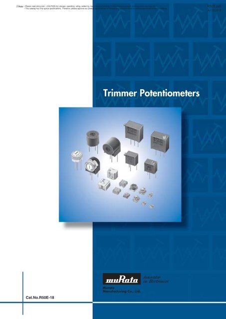
<strong>Trimmer</strong> <strong>Potentiometers</strong><br />
Cat.No.R50E-18
!Note • Please read rating and !CAUTION (for storage, operating, rating, soldering, mounting and handling) in this catalog to prevent smoking and/or burning, etc.<br />
• This catalog has only typical specifications. Therefore, please approve our product specifi cations or transact the approval sheet for product specifi cations before ordering.<br />
R50E.pdf<br />
Jul.23,2012<br />
EU RoHS Compliant<br />
All the products in this catalog comply with EU RoHS.<br />
EU RoHS is "the European Directive 2011/65/EU on the Restriction of the Use<br />
of Certain Hazardous Substances in Electrical and Electronic Equipment."<br />
For more details, please refer to our website '<strong>Murata</strong>'s Approach for EU RoHS'<br />
(http://www.murata.com/info/rohs.html).
!Note • Please read rating and !CAUTION (for storage, operating, rating, soldering, mounting and handling) in this catalog to prevent smoking and/or burning, etc.<br />
• This catalog has only typical specifications. Therefore, please approve our product specifi cations or transact the approval sheet for product specifi cations before ordering.<br />
CONTENTS<br />
R50E.pdf<br />
Jul.23,2012<br />
1<br />
Part Numbering 2<br />
Selection Guide of <strong>Trimmer</strong> <strong>Potentiometers</strong> 3<br />
1<br />
SMD Open Type 2mm Size PVZ2/PVA2 Series 4<br />
2<br />
2<br />
3<br />
4<br />
5<br />
6<br />
7<br />
PVZ2/PVA2 Series Notice 8<br />
SMD Open Type 3mm Size PVZ3 Series 10<br />
PVZ3 Series Notice 14<br />
SMD Sealed Type 3mm Size PVG3 Series 16<br />
PVG3 Series Notice 19<br />
SMD Sealed Type 4mm Size PVM4 Series 21<br />
PVM4 Series Notice 23<br />
SMD Sealed Type Multi-turn PVG5 Series 26<br />
PVG5 Series Notice 29<br />
Lead Sealed Type Single-turn PV32 Series 31<br />
PV32 Series Notice 34<br />
Lead Sealed Type Multi-turn PV12/PV37/PV36 Series 36<br />
PV12/PV37/PV36 Series Notice 43<br />
3<br />
4<br />
5<br />
6<br />
SMD Open Type (PVZ2/A2/Z3)/SMD Sealed Type (PVM4A_C01 Series) Specifications and Test Methods 45<br />
SMD Sealed Type (PVG3/M4A_D01/G5)/Lead Sealed Type (PV32/12/37/36) Specifications and Test Methods 46<br />
Packaging 49<br />
Recommended Adjustment Tools/Qualified Standards 52<br />
7
!Note • Please read rating and !CAUTION (for storage, operating, rating, soldering, mounting and handling) in this catalog to prevent smoking and/or burning, etc.<br />
• This catalog has only typical specifications. Therefore, please approve our product specifi cations or transact the approval sheet for product specifi cations before ordering.<br />
R50E.pdf<br />
Jul.23,2012<br />
o Part Numbering<br />
<strong>Trimmer</strong> <strong>Potentiometers</strong><br />
(Part Number)<br />
PV<br />
q<br />
Z3<br />
w<br />
A<br />
e<br />
103<br />
r<br />
C01<br />
t<br />
R00<br />
y<br />
qProduct ID<br />
Product ID<br />
PV<br />
<strong>Trimmer</strong> <strong>Potentiometers</strong><br />
rTotal Resistance<br />
Expressed by three figures. The unit is ohm. The first and second<br />
figures are significant digits, and the third figure expresses the<br />
number of zeros that follow the two figures.<br />
wSeries<br />
eAdjustment Direction /Lead Type<br />
Code Series Code<br />
Z2<br />
A2<br />
Z3<br />
G3<br />
M4<br />
G5<br />
32<br />
12<br />
36<br />
37<br />
SMD Open 2mm Size<br />
Carbon Resistive Element<br />
SMD Open 2mm Size<br />
SMD Open 3mm Size<br />
Carbon Resistive Element<br />
SMD Sealed 3mm Size<br />
SMD Sealed 4mm Size<br />
SMD Sealed 5mm Square<br />
11 turns<br />
Lead Sealed 6mm Round<br />
Single turn<br />
Lead Sealed 7mm Round<br />
4 turns<br />
Lead Sealed 10mm Square<br />
25 turns<br />
Lead Sealed 6mm Square<br />
12 turns<br />
A<br />
R<br />
A<br />
A<br />
G<br />
H<br />
K<br />
A<br />
G<br />
A<br />
A<br />
H<br />
H<br />
N<br />
P<br />
T<br />
W<br />
X<br />
W<br />
X<br />
Adjustment Direction/<br />
Lead Type<br />
Top<br />
Rear<br />
Top<br />
Top<br />
Top<br />
Top<br />
Rear<br />
Top, J-hook<br />
Top, Gull-wing<br />
Top<br />
Top<br />
Side<br />
Top, Triangle<br />
Side, Triangle<br />
Top, Triangle<br />
Side, Triangle<br />
Top, Inline<br />
Side, Inline<br />
Top, Triangle<br />
Side, Triangle<br />
Ex.)<br />
Code<br />
100<br />
102<br />
104<br />
tIndividual Specification<br />
Total Resistance<br />
10Ω<br />
1000Ω<br />
100000Ω (=100kΩ)<br />
Series Code Individual Specification Code<br />
PVA2<br />
PVZ2<br />
A01<br />
C04<br />
C01<br />
Standard Type<br />
Standard Type (High-heat Resistance<br />
Type/Ultra-thin Type)<br />
Standard Type (High-heat Resistance<br />
Type/Top Adjustment)<br />
PVZ3<br />
PVM4<br />
PV32/PV12<br />
PVG3/<br />
PV36/PV37<br />
PVG5<br />
yPackaging<br />
Code<br />
B00<br />
R00<br />
F01<br />
E01<br />
C01<br />
D01<br />
A01<br />
C01<br />
C03<br />
High Characteristic Carbon<br />
Type (only PVZ3G)<br />
High-heat Resistance Type<br />
(for Rear Adjustment)<br />
Standard Type<br />
High-reliability Type<br />
Standard Type<br />
Standard Type<br />
Standard Type<br />
Packaging<br />
Bulk<br />
Reel<br />
2
!Note • Please read rating and !CAUTION (for storage, operating, rating, soldering, mounting and handling) in this catalog to prevent smoking and/or burning, etc.<br />
• This catalog has only typical specifications. Therefore, please approve our product specifi cations or transact the approval sheet for product specifi cations before ordering.<br />
R50E.pdf<br />
Jul.23,2012<br />
Selection Guide of <strong>Trimmer</strong> <strong>Potentiometers</strong><br />
Mounting Method<br />
Surface Mount PCB Insertion Sealed Construction<br />
Construction<br />
Adjustment<br />
Open<br />
Sealed<br />
Top<br />
Side<br />
Carbon Resistive Element<br />
Cermet Resistive Element<br />
Cermet Resistive Element<br />
Cermet Resistive Element<br />
2mm size Single Turn<br />
PVZ2A_C04<br />
Low Profile (0.85mm max.)<br />
3mm size Single Turn 6mm size Single Turn 6mm size Single Turn<br />
PVG3A<br />
for Automatic Adjustment<br />
with Rotational Stop<br />
PV32H<br />
with Rotational Stop<br />
PV32N<br />
with Rotational Stop<br />
PVZ2R<br />
Rear Adjustment Low Profile with<br />
Smaller Foot print (0.9mm max.)<br />
PVG3G<br />
with Rotational Stop<br />
7mm size 4 Turns<br />
7mm size 4 Turns<br />
3mm size Single Turn<br />
PVZ3A<br />
for Automatic Adjustment<br />
PVZ3G<br />
Top Adjustment Low Profile<br />
(1.25mm max.)<br />
4mm size Single Turn<br />
PVM4<br />
5mm size 11 Turns<br />
PVG5<br />
PV12P<br />
6mm size 12 Turns<br />
PV37W<br />
PV12T<br />
6mm size 12 Turns<br />
PV37X<br />
PVZ3H<br />
Top Adjustment<br />
10mm size 25 Turns<br />
10mm size 25 Turns<br />
PVZ3K<br />
Rear Adjustment<br />
PV36W<br />
PV36X<br />
Cermet Resistive Element<br />
2mm size Single Turn<br />
PVA2<br />
for Automatic Adjustment<br />
(0.9mm max.)<br />
3
!Note • Please read rating and !CAUTION (for storage, operating, rating, soldering, mounting and handling) in this catalog to prevent smoking and/or burning, etc.<br />
• This catalog has only typical specifications. Therefore, please approve our product specifi cations or transact the approval sheet for product specifi cations before ordering.<br />
R50E.pdf<br />
Jul.23,2012<br />
1<br />
<strong>Trimmer</strong> <strong>Potentiometers</strong><br />
SMD Open Type 2mm Size PVZ2/PVA2 Series<br />
PVZ2 Series<br />
c Features<br />
1. Ultra-small and thin external dimensions of<br />
2.1(W)x2.7(L)x0.85 max. (T)mm.<br />
(Top adjustment type: PVZ2A_C04 Series)<br />
2. Ultra-small and thin external dimensions of<br />
2.1(W)x4.8(L)x0.9 max. (T)mm.<br />
(Rear adjustment type: PVZ2R_C04 Series)<br />
Compact PCB design is possible by smaller<br />
adjustment hole (3.0mm dia.) due to short wing<br />
length (4.8mm).<br />
3. Au plated termination achieves a high-density<br />
PCB mounting.<br />
4. Cross-shaped driver slot allows for in-process<br />
automatic adjustment and it provides superior<br />
adjustability.<br />
5. Two-piece parts construction achieves low cost and<br />
excellent quality.<br />
6. Special resin substrate allows high peak temperature<br />
for refl ow soldering (PVZ2_Cxx Series).<br />
7. PVZ2 series complies with RoHS directive.<br />
c Applications<br />
1. Pick-up module 6. DVC<br />
2. LCD 7. Digital camera<br />
3. Cellular phone 8. Portable audio, etc.<br />
4. PHS 9. RKE<br />
5. Pager 10. E-Book<br />
PVZ2A<br />
PVZ2R<br />
0.45±0.1<br />
∗1<br />
0.45±0.10<br />
(0.6)<br />
(0.6)<br />
1<br />
2.1 0.8±0.05<br />
0.8<br />
#2<br />
4<br />
#1 #3<br />
0.55 0.7 0.55<br />
2.4 Dia.<br />
∗1<br />
1.3<br />
2.2<br />
2.7±0.3<br />
0.5<br />
0.4<br />
Driver Plate Rotation Area:<br />
Please do not place any components<br />
more than 0.5mm in height within this area.<br />
2.1<br />
0.8<br />
#2<br />
#1 #3<br />
0.65 0.6 0.65<br />
2.4 Dia.<br />
∗1<br />
1.3<br />
2.2<br />
4.8<br />
Soldering<br />
Part<br />
∗1: Driver Plate Rotation Area<br />
0.8 +0.10<br />
-0.15<br />
Soldering Part<br />
#2<br />
0.5<br />
0.5<br />
#1 #3<br />
CLOCKWISE<br />
( Tolerance: ±0.2 ) in mm<br />
#2<br />
#1 #3<br />
CLOCKWISE<br />
( Tolerance : ±0.2 ) in mm<br />
Part Number<br />
Power Rating<br />
(W)<br />
Operating Temperature Range: -25 to 85 °C<br />
Soldering Method: Reflow/Soldering Iron<br />
Number of Turns<br />
(Effective Rotation Angle)<br />
Mechanical Rotation Angle<br />
Total Resistance Value<br />
TCR<br />
(ppm/°C)<br />
PVZ2p471C04 0.05(50°C) 1(240°±10°) Endless 470ohm±30% ±500<br />
PVZ2p102C04 0.05(50°C) 1(240°±10°) Endless 1k ohm±30% ±500<br />
PVZ2p222C04 0.05(50°C) 1(240°±10°) Endless 2.2k ohm±30% ±500<br />
PVZ2p472C04 0.05(50°C) 1(240°±10°) Endless 4.7k ohm±30% ±500<br />
PVZ2p103C04 0.05(50°C) 1(240°±10°) Endless 10k ohm±30% ±500<br />
PVZ2p223C04 0.05(50°C) 1(240°±10°) Endless 22k ohm±30% ±500<br />
PVZ2p473C04 0.05(50°C) 1(240°±10°) Endless 47k ohm±30% ±500<br />
PVZ2p104C04 0.05(50°C) 1(240°±10°) Endless 100k ohm±30% ±500<br />
PVZ2p224C04 0.05(50°C) 1(240°±10°) Endless 220k ohm±30% ±500<br />
PVZ2p474C04 0.05(50°C) 1(240°±10°) Endless 470k ohm±30% ±500<br />
PVZ2p105C04 0.05(50°C) 1(240°±10°) Endless 1M ohm±30% ±500<br />
4
!Note • Please read rating and !CAUTION (for storage, operating, rating, soldering, mounting and handling) in this catalog to prevent smoking and/or burning, etc.<br />
• This catalog has only typical specifications. Therefore, please approve our product specifi cations or transact the approval sheet for product specifi cations before ordering.<br />
R50E.pdf<br />
Jul.23,2012<br />
c Construction<br />
PVZ2A<br />
c Standard Land Pattern<br />
PVZ2A<br />
1<br />
0.9<br />
0.85 0.85<br />
1.55 1.55<br />
0.6 0.7<br />
0.6<br />
Tolerance : ±0.1<br />
( in mm)<br />
c Construction<br />
PVZ2R<br />
c Standard Land Pattern<br />
PVZ2R<br />
#2-Terminal<br />
0.9<br />
Driver Plate<br />
0.6<br />
#1-Terminal<br />
3.0 Dia.<br />
2.5<br />
Wiper<br />
2.5<br />
#3-Terminal<br />
Resistive<br />
Element<br />
Resin Substrate<br />
0.7<br />
0.6<br />
0.7<br />
0.6<br />
( Tolerance : ±0.1 ) in mm<br />
c Characteristics<br />
Humidity Exposure<br />
Res. Change: +10, -2%<br />
High Temperature<br />
Exposure<br />
Res. Change: R < = 50kohm···+2, -10%<br />
50kohm
!Note • Please read rating and !CAUTION (for storage, operating, rating, soldering, mounting and handling) in this catalog to prevent smoking and/or burning, etc.<br />
• This catalog has only typical specifications. Therefore, please approve our product specifi cations or transact the approval sheet for product specifi cations before ordering.<br />
R50E.pdf<br />
Jul.23,2012<br />
1<br />
PVA2 Series<br />
c Features<br />
1. Ultra-small and thin external dimensions of<br />
2.2(W)x2.75(L)x0.90 max.(T)mm.<br />
2. For the terminal attachment method of construction<br />
that uses neither solder nor adhesives, good<br />
solderability and terminal attachment intensity<br />
are realized.<br />
3. Because of multi-contact wiper structure, PVA2 has<br />
a stable characteristics (low noise).<br />
4. PVA2 series does not use a solder, fl ux or cleaning<br />
solvent, so they are environmentally friendly<br />
products.<br />
5. Heat resistance performance enables high temperature<br />
peak refl ow soldering.<br />
6. PVA2 series complies with RoHS directive.<br />
1.3<br />
0.45±0.1<br />
#1<br />
2.2<br />
#2<br />
#3<br />
0.8±0.1<br />
2.4 Dia<br />
0.4<br />
1.3<br />
2.75<br />
0.75<br />
0.5 0.6<br />
0.8<br />
0.9 0.6<br />
0.5<br />
Resin<br />
#2 (Wiper Contact)<br />
#1 #3<br />
CLOCKWISE<br />
CIRCUIT<br />
( Tolerance: ±0.2 ) in mm<br />
c Applications<br />
1. Thin-model optical pick-up module<br />
2. LCD module<br />
3. Optical communication module<br />
4. Small sensor module<br />
5. Digital camera<br />
6. Small telecommunications equipment, etc.<br />
7. E-Book<br />
Part Number<br />
Power Rating<br />
(W)<br />
Number of Turns<br />
(Effective Rotation Angle)<br />
Mechanical Rotation Angle<br />
Total Resistance Value<br />
TCR<br />
(ppm/°C)<br />
PVA2A101A01 0.1(70°C) 1(260°±10°) Endless 100ohm±25% ±250<br />
PVA2A221A01 0.1(70°C) 1(260°±10°) Endless 220ohm±25% ±250<br />
PVA2A471A01 0.1(70°C) 1(260°±10°) Endless 470ohm±25% ±250<br />
PVA2A102A01 0.1(70°C) 1(260°±10°) Endless 1k ohm±25% ±250<br />
PVA2A222A01 0.1(70°C) 1(260°±10°) Endless 2.2k ohm±25% ±250<br />
PVA2A472A01 0.1(70°C) 1(260°±10°) Endless 4.7k ohm±25% ±250<br />
PVA2A103A01 0.1(70°C) 1(260°±10°) Endless 10k ohm±25% ±250<br />
PVA2A223A01 0.1(70°C) 1(260°±10°) Endless 22k ohm±25% ±250<br />
PVA2A473A01 0.1(70°C) 1(260°±10°) Endless 47k ohm±25% ±250<br />
PVA2A104A01 0.1(70°C) 1(260°±10°) Endless 100k ohm±25% ±250<br />
PVA2A224A01 0.1(70°C) 1(260°±10°) Endless 220k ohm±25% ±250<br />
PVA2A474A01 0.1(70°C) 1(260°±10°) Endless 470k ohm±25% ±250<br />
PVA2A105A01 0.1(70°C) 1(260°±10°) Endless 1M ohm±25% ±250<br />
PVA2A225A01 0.1(70°C) 1(260°±10°) Endless 2.2M ohm±25% ±250<br />
Operating Temperature Range: -55 to 125 °C<br />
Soldering Method: Reflow/Soldering Iron<br />
6
!Note • Please read rating and !CAUTION (for storage, operating, rating, soldering, mounting and handling) in this catalog to prevent smoking and/or burning, etc.<br />
• This catalog has only typical specifications. Therefore, please approve our product specifi cations or transact the approval sheet for product specifi cations before ordering.<br />
R50E.pdf<br />
Jul.23,2012<br />
c Construction<br />
Driver Plate<br />
c Standard Land Pattern<br />
1.1<br />
1<br />
Wiper<br />
#2-Terminal<br />
1.55<br />
#1-Terminal<br />
1.70<br />
0.85<br />
0.90<br />
Resistive Element<br />
0.70<br />
#3-Terminal<br />
Ceramic Substrate<br />
1.90<br />
( Tolerance : ±0.1 ) in mm<br />
c Characteristics<br />
Humidity Exposure<br />
Res. Change: ±3%<br />
High Temperature<br />
Exposure<br />
Res. Change: ±3%<br />
Humidity Load Life<br />
Res. Change: ±3%<br />
Load Life<br />
Res. Change: ±3%<br />
Temperature Cycle<br />
Res. Change: ±3%<br />
Rotational Life<br />
Res. Change: ±10% (10 cycles)<br />
7
!Note • Please read rating and !CAUTION (for storage, operating, rating, soldering, mounting and handling) in this catalog to prevent smoking and/or burning, etc.<br />
• This catalog has only typical specifications. Therefore, please approve our product specifi cations or transact the approval sheet for product specifi cations before ordering.<br />
R50E.pdf<br />
Jul.23,2012<br />
1<br />
PVZ2/PVA2 Series Notice<br />
c Notice (Operating and Storage Conditions)<br />
1. Store in temperatures of -10 to +40°C and<br />
relative humidity of 30-85%.<br />
2. Do not store in or near corrosive gases.<br />
3. Use within six months after delivery.<br />
4. Open the package just before using.<br />
5. Do not store under direct sunlight.<br />
6. If you use the trimmer potentiometer in an<br />
environment other than listed at right, please<br />
consult with a <strong>Murata</strong> factory representative prior<br />
to using.<br />
The trimmer potentiometer should not be used under<br />
the following environmental conditions:<br />
(1) Corrosive gaseous atmosphere<br />
(Ex. Chlorine gas, Hydrogen sulfi de gas, Ammonia<br />
gas, Sulfuric acid gas, Nitric oxide gas, etc.)<br />
(2) In liquid<br />
(Ex. Oil, Medical liquid, Organic solvent, etc.)<br />
(3) Dusty/dirty atmosphere<br />
(4) Direct sunlight<br />
(5) Static voltage or electric/magnetic fi elds<br />
(6) Direct sea breeze<br />
(7) Other variations of the above<br />
c Notice (Rating)<br />
1. When using with partial load (rheostat), minimize<br />
the power depending on the resistance value.<br />
2. The maximum input voltage to a trimmer<br />
potentiometer should not exceed (P·R)^1/2 or the<br />
maximum operating voltage, whichever is smaller.<br />
3. If the trimmer potentiometer is used in DC and high<br />
humidity conditions, please connect wiper (#2) for<br />
plus and resistive element (#1 or #3) for minus.<br />
(PVZ Series only)<br />
c Notice (Soldering and Mounting)<br />
1. Soldering<br />
(1) Refl ow soldering method and soldering iron are<br />
available. This product cannot be soldered using<br />
the fl ow soldering method (dipping). If you use the<br />
fl ow soldering method, the trimmer potentiometer<br />
may not function.<br />
(2) Use our standard land dimension. Excessive land<br />
area causes displacement due to the effect of<br />
the surface tension of the solder. Insuffi cient<br />
land area leads to insuffi cient soldering<br />
strength of the chip.<br />
(3) Soldering conditions<br />
Refer to the temperature profi le.<br />
If the soldering conditions are not suitable,<br />
e.g., excessive time and/or excessive<br />
temperature, the trimmer potentiometer may<br />
deviate from the specifi ed characteristics.<br />
(4) Apply the appropriate amount of solder paste.<br />
The thickness of solder paste should be printed<br />
from 100 micro m to 150 micro m and the<br />
dimension of land pattern used should be <strong>Murata</strong>'s<br />
standard land pattern at refl ow soldering.<br />
Insuffi cient amounts of solder can lead to<br />
insuffi cient soldering strength on PCB.<br />
Excessive amounts of solder may cause bridging<br />
between the terminals.<br />
(5) The soldering iron should not come in contact<br />
with the case of the trimmer potentiometer. If<br />
such contact does occur, the trimmer<br />
potentiometer may be damaged.<br />
2. Mounting<br />
(1) Do not apply excessive force, preferably 4.9N<br />
max. (Ref. 500gf) when the trimmer<br />
potentiometer is mounted to the PCB.<br />
(2) Do not warp and/or bend the PC board to protect<br />
trimmer potentiometer from breakage.<br />
(3) In chip placers, the recommended size of the<br />
cylindrical pick-up nozzle should be outer<br />
dimension 1.5-1.8mm dia. and inner dimension<br />
1.3mm dia.<br />
3. Cleaning<br />
(1) In case there is fl ux on the resistive element,<br />
clean suffi ciently with cleaning solvents and<br />
completely remove all residual fl ux.<br />
(2) Isopropyl alcohol and ethyl alcohol are<br />
applicable solvents for cleaning. If you use any<br />
other types of solvents, please evaluate<br />
performance with your product.<br />
Continued on the following page.<br />
8
!Note • Please read rating and !CAUTION (for storage, operating, rating, soldering, mounting and handling) in this catalog to prevent smoking and/or burning, etc.<br />
• This catalog has only typical specifications. Therefore, please approve our product specifi cations or transact the approval sheet for product specifi cations before ordering.<br />
PVZ2/PVA2 Series Notice<br />
Continued from the preceding page.<br />
c Soldering Profile<br />
Reflow Soldering Profile<br />
1. Soldering profile for lead free solder (96.5Sn/3.0Ag/0.5Cu)<br />
R50E.pdf<br />
Jul.23,2012<br />
1<br />
Temperature (°C)<br />
T1<br />
T3<br />
T2<br />
t2<br />
t3<br />
T5<br />
T4<br />
Limit Profile<br />
Standard Profile<br />
t1<br />
Time (s)<br />
PVZ2<br />
PVA2<br />
Series<br />
Standard Profile<br />
Pre-heating Heating Peak<br />
Cycle of<br />
Temperature<br />
Temp. (T1) Time (t1) Temp. (T2) Time (t2) (T3) Reflow<br />
°C sec. °C sec. °C Time<br />
150 to 180 60 to 120 220 30 to 60 245±3 2<br />
150 to 180 60 to 120 220 30 to 60 245±3 2<br />
Limit Profile<br />
Pre-heating Heating Peak<br />
Cycle of<br />
Temperature<br />
Temp. (T1) Time (t1) Temp. (T4) Time (t3) (T5) Reflow<br />
°C sec. °C sec. °C Time<br />
150 to 180 60 to 120 220 30 to 60 260 2<br />
150 to 180 60 to 120 220 30 to 60 260 +5/-0 2<br />
2. Soldering profile for Eutectic solder (63Sn/37Pb)<br />
(Limit profile: refer to 1)<br />
Temperature (°C)<br />
T1<br />
T3<br />
T2<br />
t2<br />
Standard Profile<br />
PVZ2<br />
PVA2<br />
Series<br />
Standard Profile<br />
Pre-heating Heating Peak<br />
Cycle of<br />
Temperature<br />
Temp. (T1) Time (t1) Temp. (T2) Time (t2) (T3) Reflow<br />
°C sec. °C sec. °C Time<br />
150 60 to 120 183 30<br />
230<br />
1<br />
t1<br />
time (s)<br />
Soldering Iron<br />
PVZ2<br />
PVA2<br />
Series<br />
Standard Condition<br />
Temperature of Soldering Iron Tip Soldering Time Soldering Iron Power Output Cycle of Soldering Iron<br />
°C sec. W Time<br />
350±10 3 max. 30 max. 1<br />
c Notice (Handling)<br />
1. Use suitable screwdrivers that fi t comfortably in the<br />
driver slot. We recommend the screwdriver below.<br />
* Recommended screwdriver for manual adjustment<br />
<strong>Murata</strong> P/N: KMDR190<br />
2. The screwdriver should be set in the products<br />
vertically, do not apply more than 4.9N (Ref. 500gf)<br />
of twist and stress after mounting onto PCB to<br />
prevent contact intermittence. If excessive force is<br />
applied, the trimmer potentiometer may not function.<br />
3. Please use within the effective rotational angle.<br />
The trimmer potentiometer does not have a<br />
mechanical stop for over rotation. In cases out of<br />
effective rotational angle, the trimmer<br />
potentiometer may not function.<br />
4. When using a lock paint to fi x the slot position or<br />
cover the rotor, please evaluate performance with<br />
your product. Lock paint may cause corrosion or<br />
electrical contact problems.<br />
c Notice (Other)<br />
1. Please make sure that your product has been<br />
evaluated and confi rmed against your<br />
specifi cations when our product is mounted to your<br />
product.<br />
2. <strong>Murata</strong> cannot guarantee trimmer potentiometer<br />
integrity when used under conditions other than<br />
those specifi ed in this document.<br />
9
!Note • Please read rating and !CAUTION (for storage, operating, rating, soldering, mounting and handling) in this catalog to prevent smoking and/or burning, etc.<br />
• This catalog has only typical specifications. Therefore, please approve our product specifi cations or transact the approval sheet for product specifi cations before ordering.<br />
R50E.pdf<br />
Jul.23,2012<br />
<strong>Trimmer</strong> <strong>Potentiometers</strong><br />
SMD Open Type 3mm Size PVZ3 Series<br />
2 PVZ3 Series<br />
c Features<br />
1. Excellent solderability characteristics are<br />
achieved via special plating techniques on each<br />
termination.<br />
2. Specially designed substrate prevents wicking of<br />
fl ux onto the top of the part body.<br />
3. Funnel shaped adjustment slot allows for in-process<br />
automatic adjustment.<br />
(PVZ3A/PVZ3H/PVZ3K Series)<br />
4. High-heat resistance type is available<br />
(PVZ3A_C01/PVZ3K_E01).<br />
5. Enlarged bottom termination enhances soldering<br />
strength while reducing the necessary land area<br />
required, promoting high-density PCB mounting<br />
(PVZ3A/PVZ3H/PVZ3G Series).<br />
6. The standard position of the driver plate is adjusted<br />
at the center normally, but another position is also<br />
available.<br />
7. This product meets PB-free standards.<br />
8. Complies with RoHS directive.<br />
PVZ3A<br />
3.6<br />
0.5±0.1<br />
3.1<br />
1.0<br />
#2<br />
2.4±0.1<br />
0.75<br />
#1<br />
1.0<br />
#3<br />
0.75<br />
Soldering Part<br />
0.5<br />
3.1<br />
0.8<br />
#2<br />
1.15 Dia.<br />
2.2 Dia.<br />
0.25±0.1 0.1 max.<br />
3.0 Dia.<br />
0.7<br />
0.7<br />
0.55 0.6<br />
3.2<br />
ø1.15<br />
ø2.2<br />
ø3.0<br />
1.85±0.1<br />
#2<br />
#1 #3<br />
CLOCKWISE<br />
0.25<br />
( Tolerance: ±0.3 )<br />
in mm<br />
1.55<br />
0.40<br />
0.40<br />
c Applications<br />
1. Optical pick up 6. CD-ROMs<br />
2. Cordless telephones 7. Car stereos<br />
3. CD players 8. TFT-LCD TV sets<br />
4. E-Book 9. Headphone stereos<br />
5. Motor<br />
PVZ3H<br />
2.4<br />
R0.75<br />
R1.5<br />
3.1<br />
0.8<br />
#2<br />
3.1<br />
#1 #3<br />
0.55 1.2 0.55<br />
3.6<br />
in mm<br />
( Tolerance : ±0.3 )<br />
1.15±0.10<br />
0.4<br />
2.1±0.1<br />
0.5±0.1<br />
3.1<br />
3.6<br />
0.55 #1 1.2 #3 0.55<br />
0.6<br />
#2 (Wiper Contact)<br />
#1 #3<br />
CLOCKWISE<br />
PVZ3G<br />
0.55<br />
CIRCUIT<br />
Tolerance: ±0.3<br />
( in mm)<br />
3.1<br />
#2<br />
2.1<br />
1.85±0.1<br />
0.25±0.1<br />
3.2<br />
PVZ3K<br />
5.4<br />
4.4<br />
#3 #1<br />
1.1 Soldering Part<br />
1.15 Dia.<br />
2.2 Dia.<br />
3.0 Dia.<br />
0.85 0.9 0.85<br />
0.5±0.1<br />
2.4±0.1<br />
#2 (Wiper Contact)<br />
#1 #3<br />
CLOCKWISE<br />
CIRCUIT<br />
( Tolerance: ±0.3 ) in mm<br />
10
!Note • Please read rating and !CAUTION (for storage, operating, rating, soldering, mounting and handling) in this catalog to prevent smoking and/or burning, etc.<br />
• This catalog has only typical specifications. Therefore, please approve our product specifi cations or transact the approval sheet for product specifi cations before ordering.<br />
R50E.pdf<br />
Jul.23,2012<br />
Top Adjustment (H 1.85)<br />
Part Number<br />
Power Rating<br />
(W)<br />
Number of Turns<br />
(Effective Rotation Angle)<br />
Mechanical Rotation Angle<br />
Total Resistance Value<br />
TCR<br />
(ppm/°C)<br />
PVZ3A221C01 0.1(50°C) 1(230°±10°) Endless 220ohm±30% ±500<br />
PVZ3A471C01 0.1(50°C) 1(230°±10°) Endless 470ohm±30% ±500<br />
PVZ3A102C01 0.1(50°C) 1(230°±10°) Endless 1k ohm±30% ±500<br />
PVZ3A222C01 0.1(50°C) 1(230°±10°) Endless 2.2k ohm±30% ±500<br />
PVZ3A472C01 0.1(50°C) 1(230°±10°) Endless 4.7k ohm±30% ±500<br />
PVZ3A103C01 0.1(50°C) 1(230°±10°) Endless 10k ohm±30% ±500<br />
PVZ3A223C01 0.1(50°C) 1(230°±10°) Endless 22k ohm±30% ±500<br />
PVZ3A473C01 0.1(50°C) 1(230°±10°) Endless 47k ohm±30% ±500<br />
PVZ3A104C01 0.1(50°C) 1(230°±10°) Endless 100k ohm±30% ±500<br />
PVZ3A224C01 0.1(50°C) 1(230°±10°) Endless 220k ohm±30% ±500<br />
PVZ3A474C01 0.1(50°C) 1(230°±10°) Endless 470k ohm±30% ±500<br />
PVZ3A105C01 0.1(50°C) 1(230°±10°) Endless 1M ohm±30% ±500<br />
PVZ3A225C01 0.1(50°C) 1(230°±10°) Endless 2.2M ohm±30% ±500<br />
Operating Temperature Range: -25 to 85 °C<br />
Soldering Method: Reflow/Soldering Iron<br />
2<br />
Top Adjustment (H 1.55)<br />
Part Number<br />
Power Rating<br />
(W)<br />
Number of Turns<br />
(Effective Rotation Angle)<br />
Mechanical Rotation Angle<br />
Total Resistance Value<br />
TCR<br />
(ppm/°C)<br />
PVZ3H221C01 0.1(50°C) 1(230°±10°) Endless 220ohm±30% ±500<br />
PVZ3H471C01 0.1(50°C) 1(230°±10°) Endless 470ohm±30% ±500<br />
PVZ3H102C01 0.1(50°C) 1(230°±10°) Endless 1k ohm±30% ±500<br />
PVZ3H222C01 0.1(50°C) 1(230°±10°) Endless 2.2k ohm±30% ±500<br />
PVZ3H472C01 0.1(50°C) 1(230°±10°) Endless 4.7k ohm±30% ±500<br />
PVZ3H103C01 0.1(50°C) 1(230°±10°) Endless 10k ohm±30% ±500<br />
PVZ3H223C01 0.1(50°C) 1(230°±10°) Endless 22k ohm±30% ±500<br />
PVZ3H473C01 0.1(50°C) 1(230°±10°) Endless 47k ohm±30% ±500<br />
PVZ3H104C01 0.1(50°C) 1(230°±10°) Endless 100k ohm±30% ±500<br />
PVZ3H224C01 0.1(50°C) 1(230°±10°) Endless 220k ohm±30% ±500<br />
PVZ3H474C01 0.1(50°C) 1(230°±10°) Endless 470k ohm±30% ±500<br />
PVZ3H105C01 0.1(50°C) 1(230°±10°) Endless 1M ohm±30% ±500<br />
PVZ3H225C01 0.1(50°C) 1(230°±10°) Endless 2.2M ohm±30% ±500<br />
Operating Temperature Range: -25 to 85 °C<br />
Soldering Method: Reflow/Soldering Iron<br />
Top Adjustment and Thin Type (H 1.15)<br />
Part Number<br />
Power Rating<br />
(W)<br />
Number of Turns<br />
(Effective Rotation Angle)<br />
Mechanical Rotation Angle<br />
Total Resistance Value<br />
TCR<br />
(ppm/°C)<br />
PVZ3G221C01 0.1(50°C) 1(230°±10°) Endless 220ohm±30% ±500<br />
PVZ3G471C01 0.1(50°C) 1(230°±10°) Endless 470ohm±30% ±500<br />
PVZ3G102C01 0.1(50°C) 1(230°±10°) Endless 1k ohm±30% ±500<br />
PVZ3G222C01 0.1(50°C) 1(230°±10°) Endless 2.2k ohm±30% ±500<br />
PVZ3G472C01 0.1(50°C) 1(230°±10°) Endless 4.7k ohm±30% ±500<br />
PVZ3G103C01 0.1(50°C) 1(230°±10°) Endless 10k ohm±30% ±500<br />
PVZ3G223C01 0.1(50°C) 1(230°±10°) Endless 22k ohm±30% ±500<br />
PVZ3G473C01 0.1(50°C) 1(230°±10°) Endless 47k ohm±30% ±500<br />
PVZ3G104C01 0.1(50°C) 1(230°±10°) Endless 100k ohm±30% ±500<br />
PVZ3G224C01 0.1(50°C) 1(230°±10°) Endless 220k ohm±30% ±500<br />
PVZ3G474C01 0.1(50°C) 1(230°±10°) Endless 470k ohm±30% ±500<br />
PVZ3G105C01 0.1(50°C) 1(230°±10°) Endless 1M ohm±30% ±500<br />
PVZ3G225C01 0.1(50°C) 1(230°±10°) Endless 2.2M ohm±30% ±500<br />
Operating Temperature Range: -25 to 85 °C<br />
Soldering Method: Reflow/Soldering Iron<br />
11
!Note • Please read rating and !CAUTION (for storage, operating, rating, soldering, mounting and handling) in this catalog to prevent smoking and/or burning, etc.<br />
• This catalog has only typical specifications. Therefore, please approve our product specifi cations or transact the approval sheet for product specifi cations before ordering.<br />
R50E.pdf<br />
Jul.23,2012<br />
Rear Adjustment<br />
Part Number<br />
Power Rating<br />
(W)<br />
Number of Turns<br />
(Effective Rotation Angle)<br />
Mechanical Rotation Angle<br />
Total Resistance Value<br />
TCR<br />
(ppm/°C)<br />
PVZ3K221E01 0.1(50°C) 1(230°±10°) Endless 220ohm±30% ±500<br />
PVZ3K471E01 0.1(50°C) 1(230°±10°) Endless 470ohm±30% ±500<br />
PVZ3K102E01 0.1(50°C) 1(230°±10°) Endless 1k ohm±30% ±500<br />
2<br />
PVZ3K222E01 0.1(50°C) 1(230°±10°) Endless 2.2k ohm±30% ±500<br />
PVZ3K472E01 0.1(50°C) 1(230°±10°) Endless 4.7k ohm±30% ±500<br />
PVZ3K103E01 0.1(50°C) 1(230°±10°) Endless 10k ohm±30% ±500<br />
PVZ3K223E01 0.1(50°C) 1(230°±10°) Endless 22k ohm±30% ±500<br />
PVZ3K473E01 0.1(50°C) 1(230°±10°) Endless 47k ohm±30% ±500<br />
PVZ3K104E01 0.1(50°C) 1(230°±10°) Endless 100k ohm±30% ±500<br />
PVZ3K224E01 0.1(50°C) 1(230°±10°) Endless 220k ohm±30% ±500<br />
PVZ3K474E01 0.1(50°C) 1(230°±10°) Endless 470k ohm±30% ±500<br />
PVZ3K105E01 0.1(50°C) 1(230°±10°) Endless 1M ohm±30% ±500<br />
PVZ3K225E01 0.1(50°C) 1(230°±10°) Endless 2.2M ohm±30% ±500<br />
Operating Temperature Range: -25 to 85 °C<br />
Soldering Method: Reflow/Soldering Iron<br />
c Construction<br />
PVZ3A<br />
c Construction<br />
PVZ3G<br />
c Standard Land Pattern<br />
PVZ3A/PVZ3G/PVZ3H<br />
Driver Plate<br />
Wiper<br />
1.1<br />
#2-Terminal<br />
1.9<br />
0.9<br />
Resistive<br />
Element<br />
1.9<br />
#1-Terminal<br />
#3-Terminal<br />
Resin Substrate<br />
0.9<br />
1.0 0.7 1.0<br />
Tolerance : ±0.1<br />
( in mm)<br />
c Construction<br />
PVZ3H<br />
Driver Plate<br />
Wiper<br />
#1 Terminal1<br />
4<br />
#2 Terminal<br />
Resistive Element<br />
#3 Terminal<br />
Resin Substrate<br />
Continued on the following page.<br />
12
!Note • Please read rating and !CAUTION (for storage, operating, rating, soldering, mounting and handling) in this catalog to prevent smoking and/or burning, etc.<br />
• This catalog has only typical specifications. Therefore, please approve our product specifi cations or transact the approval sheet for product specifi cations before ordering.<br />
Continued from the preceding page.<br />
c Construction<br />
#1-Terminal<br />
PVZ3K<br />
#2-Terminal<br />
Driver Plate<br />
c Standard Land Pattern<br />
PVZ3K<br />
1.5<br />
R50E.pdf<br />
Jul.23,2012<br />
4.0<br />
1.0<br />
3.0 Dia<br />
2<br />
#3-Terminal<br />
Wiper<br />
Resistive Element<br />
(Carbon)<br />
Resin Substrate<br />
1.0<br />
0.5<br />
3.0<br />
Tolerance : ±0.1<br />
( in mm)<br />
c Characteristics<br />
Humidity Exposure<br />
Res. Change: +10, -2%<br />
High Temperature<br />
Exposure<br />
Res. Change: R < = 100kohm···+2, -10%<br />
100kohm
!Note • Please read rating and !CAUTION (for storage, operating, rating, soldering, mounting and handling) in this catalog to prevent smoking and/or burning, etc.<br />
• This catalog has only typical specifications. Therefore, please approve our product specifi cations or transact the approval sheet for product specifi cations before ordering.<br />
R50E.pdf<br />
Jul.23,2012<br />
PVZ3 Series Notice<br />
2<br />
c Notice (Operating and Storage Conditions)<br />
1. Store in temperatures of -10 to +40°C and<br />
relative humidity of 30-85%.<br />
2. Do not store in or near corrosive gases.<br />
3. Use within six months after delivery.<br />
4. Open the package just before using.<br />
5. Do not store under direct sunlight.<br />
6. If you use the trimmer potentiometer in an<br />
environment other than listed at right, please<br />
consult with a <strong>Murata</strong> factory representative prior<br />
to using.<br />
The trimmer potentiometer should not be used under<br />
the following environmental conditions:<br />
(1) Corrosive gaseous atmosphere<br />
(Ex. Chlorine gas, Hydrogen sulfi de gas, Ammonia<br />
gas, Sulfuric acid gas, Nitric oxide gas, etc.)<br />
(2) In liquid<br />
(Ex. Oil, Medical liquid, Organic solvent, etc.)<br />
(3) Dusty/dirty atmosphere<br />
(4) Direct sunlight<br />
(5) Static voltage or electric/magnetic fi elds<br />
(6) Direct sea breeze<br />
(7) Other variations of the above<br />
c Notice (Rating)<br />
1. When using with partial load (rheostat), minimize<br />
the power depending on the resistance value.<br />
2. The maximum input voltage to a trimmer<br />
potentiometer should not exceed (P·R)^1/2 or the<br />
maximum operating voltage, whichever is smaller.<br />
3. If the trimmer potentiometer is used in DC and high<br />
humidity conditions, please connect wiper (#2) for<br />
plus and resistive element (#1 or #3) for minus.<br />
c Notice (Soldering and Mounting)<br />
1. Soldering<br />
(1) Soldering conditions<br />
Refer to the temperature profi le.<br />
If the soldering conditions are not suitable,<br />
e.g., excessive time and/or excessive<br />
temperature, the trimmer potentiometer may<br />
deviate from the specifi ed characteristics.<br />
Do not use fl ow soldering method (dipping).<br />
If you use the fl ow soldering method, the<br />
trimmer potentiometer may not function.<br />
(2) Use our standard land dimension. Excessive land<br />
area causes displacement due to the effect of<br />
the surface tension of the solder. Insuffi cient<br />
land area leads to insuffi cient soldering<br />
strength of the chip.<br />
(3) Apply the appropriate amount of solder paste.<br />
The thickness of solder paste should be printed<br />
from 100 micro m to 150 micro m and the dimension<br />
of land pattern used should be <strong>Murata</strong>'s standard<br />
land pattern at refl ow soldering. Insuffi cient<br />
amounts of solder can lead to insuffi cient<br />
soldering strength on PCB.<br />
Excessive amounts of solder may cause bridging<br />
between the terminals.<br />
(4) The soldering iron should not come in contact with<br />
the case of the trimmer potentiometer. If such<br />
contact does occur, the trimmer potentiometer<br />
may be damaged. (PVZ Series only)<br />
2. Mounting<br />
(1) Do not apply excessive force, preferably 4.9N<br />
max. (Ref. 500gf) when the trimmer potentiometer<br />
is mounted to the PCB.<br />
(2) Do not warp and/or bend the PC board to protect<br />
trimmer potentiometer from breakage.<br />
(3) In chip placers, the recommended size of the<br />
cylindrical pick-up nozzle should be outer<br />
dimension 2.5-2.8mm dia. and inner dimension<br />
2mm dia.<br />
3. Cleaning<br />
(1) In case there is fl ux on the resistive element,<br />
clean suffi ciently with cleaning solvents and<br />
completely remove all residual fl ux.<br />
(2) Isopropyl alcohol and ethyl alcohol are<br />
applicable solvents for cleaning. If you use any<br />
other types of solvents, please evaluate<br />
performance with your product.<br />
Continued on the following page.<br />
14
!Note • Please read rating and !CAUTION (for storage, operating, rating, soldering, mounting and handling) in this catalog to prevent smoking and/or burning, etc.<br />
• This catalog has only typical specifications. Therefore, please approve our product specifi cations or transact the approval sheet for product specifi cations before ordering.<br />
R50E.pdf<br />
Jul.23,2012<br />
PVZ3 Series Notice<br />
Continued from the preceding page.<br />
c Soldering Profile<br />
Reflow Soldering Profile<br />
1. Soldering profile for lead free solder (96.5Sn/3.0Ag/0.5Cu)<br />
Temperature (°C)<br />
T1<br />
T3<br />
T2<br />
t2<br />
t3<br />
T5<br />
T4<br />
Limit Profile<br />
Standard Profile<br />
2<br />
t1<br />
Time (s)<br />
PVZ3<br />
Series<br />
Standard Profile<br />
Limit Profile<br />
Pre-heating Heating Peak<br />
Cycle of Pre-heating<br />
Heating<br />
Peak<br />
Cycle of<br />
Temperature<br />
Temperature<br />
Temp. (T1) Time (t1) Temp. (T2) Time (t2) (T3) Reflow Temp. (T1) Time (t1) Temp. (T4) Time (t3) (T5) Reflow<br />
°C sec. °C sec. °C Time °C sec. °C sec. °C Time<br />
150 to 180 60 to 120 220 30 to 60 245±3 2 150 to 180 60 to 120 220 30 to 60 260 2<br />
2. Soldering profile for Eutectic solder (63Sn/37Pb)<br />
(Limit profile: refer to 1)<br />
Temperature (°C)<br />
T1<br />
T3<br />
T2<br />
t2<br />
Standard Profile<br />
PVZ3<br />
Series<br />
Standard Profile<br />
Pre-heating<br />
Heating<br />
Temp. (T1) Time (t1) Temp. (T2) Time (t2)<br />
°C sec. °C sec.<br />
150 60 to 120 183 30<br />
Peak<br />
Temperature<br />
(T3)<br />
°C<br />
230 max.<br />
Cycle of<br />
Reflow<br />
Time<br />
1<br />
t1<br />
Time (s)<br />
Soldering Iron<br />
Standard Condition<br />
Series Temperature of Soldering Iron Tip Soldering Time Soldering Iron Power Output Cycle of Soldering Iron<br />
°C sec. W Time<br />
PVZ3<br />
350±10 3 max. 30 max. 1<br />
c Notice (Handling)<br />
1. Use suitable screwdrivers that fi t comfortably in the<br />
driver slot. We recommend the screwdrivers below.<br />
* Recommended screwdriver for manual adjustment<br />
>VESSEL MFG.: NO.9000+1.7x30<br />
(<strong>Murata</strong> P/N: KMDR080)<br />
* Recommended screwdriver for automatic adjustment<br />
>TORAY MFG.: JB-2225 (<strong>Murata</strong> P/N: KMBT070)<br />
2. Don't apply more than 4.9N (Ref.; 500gf) of twist<br />
and stress after mounting onto PCB to prevent<br />
contact intermittence. If excessive force is<br />
applied, the trimmer potentiometer may not<br />
function.<br />
3. Please use within the effective rotational angle.<br />
Do not have a mechanical stop for over rotation.<br />
In cases out of effective rotational angle,<br />
the trimmer potentiometer may not function.<br />
4. When using a lock paint to fi x the slot position or<br />
cover the rotor, please evaluate performance with<br />
your product. Lock paint may cause corrosion or<br />
electrical contact problems.<br />
c Notice (Other)<br />
1. Please make sure that your product has been<br />
evaluated and confi rmed against your<br />
specifi cations when our product is mounted to your<br />
product.<br />
2. <strong>Murata</strong> cannot guarantee trimmer potentiometer<br />
integrity when used under conditions other than<br />
those specifi ed in this document.<br />
15
!Note • Please read rating and !CAUTION (for storage, operating, rating, soldering, mounting and handling) in this catalog to prevent smoking and/or burning, etc.<br />
• This catalog has only typical specifications. Therefore, please approve our product specifi cations or transact the approval sheet for product specifi cations before ordering.<br />
R50E.pdf<br />
Jul.23,2012<br />
<strong>Trimmer</strong> <strong>Potentiometers</strong><br />
SMD Sealed Type 3mm Size PVG3 Series<br />
3<br />
c Features<br />
1. Sealed construction protects the interior from dust<br />
and liquid, which achieves stable performance.<br />
2. Driver plate with cross-slot is suitable for<br />
automatic adjustment.<br />
3. Rotor with large diameter and deep groove improves<br />
driver insertion.<br />
4. 3mm and 4mm land pattern can be used without change.<br />
(Gull-wing is suitable for 4mm size land pattern.)<br />
5. Heat resistance performance enables high<br />
temperature peak refl ow soldering.<br />
6. Complies with RoHS directive by new Cd free cermet<br />
resistive material. Pb free terminals with<br />
Sn plating.<br />
c Applications<br />
1. Small sensors 5. Compact Power Supply<br />
2. Optical Transceiver Module 6. Wireless Radio module<br />
3. Copier 7. Corner Sensor<br />
4. Printer 8. E-Book<br />
PVG3A<br />
#3<br />
#3<br />
#2<br />
#2<br />
3.6<br />
2.3<br />
3.6<br />
2.3<br />
0.45<br />
0.4 Depth<br />
#1<br />
3.6 2.2 Dia.<br />
0.45<br />
0.4 Depth<br />
#1<br />
4.5 2.2 Dia.<br />
3.4<br />
2.7<br />
3.4<br />
2.7<br />
2.0<br />
1.00±0.15<br />
0.75±0.15<br />
2.0<br />
0.1 Min.<br />
0.6<br />
1.00±0.15<br />
#2<br />
#1 #3<br />
CLOCKWISE<br />
Tolerance : ±0.3<br />
( in mm )<br />
0.1 Min.<br />
#2<br />
PVG3G<br />
0.75±0.15<br />
#1 #3<br />
CLOCKWISE<br />
Tolerance : ±0.3<br />
( in mm )<br />
Top Adjustment (Standard Type)<br />
Part Number<br />
Power Rating<br />
(W)<br />
Operating Temperature Range: -55 to 125 °C<br />
Soldering Method: Reflow/Soldering Iron<br />
Number of Turns<br />
(Effective Rotation Angle)<br />
Mechanical Rotation Angle<br />
Total Resistance Value<br />
TCR<br />
(ppm/°C)<br />
PVG3A100C01 0.25(70°C) 1(210°±10°) 250+/-10 deg. 10ohm±20% ±150<br />
PVG3A200C01 0.25(70°C) 1(210°±10°) 250+/-10 deg. 20ohm±20% ±150<br />
PVG3A500C01 0.25(70°C) 1(210°±10°) 250+/-10 deg. 50ohm±20% ±150<br />
PVG3A101C01 0.25(70°C) 1(210°±10°) 250+/-10 deg. 100ohm±20% ±150<br />
PVG3A201C01 0.25(70°C) 1(210°±10°) 250+/-10 deg. 200ohm±20% ±150<br />
PVG3A501C01 0.25(70°C) 1(210°±10°) 250+/-10 deg. 500ohm±20% ±150<br />
PVG3A102C01 0.25(70°C) 1(210°±10°) 250+/-10 deg. 1k ohm±20% ±150<br />
PVG3A202C01 0.25(70°C) 1(210°±10°) 250+/-10 deg. 2k ohm±20% ±150<br />
PVG3A502C01 0.25(70°C) 1(210°±10°) 250+/-10 deg. 5k ohm±20% ±150<br />
PVG3A103C01 0.25(70°C) 1(210°±10°) 250+/-10 deg. 10k ohm±20% ±150<br />
PVG3A203C01 0.25(70°C) 1(210°±10°) 250+/-10 deg. 20k ohm±20% ±150<br />
PVG3A503C01 0.25(70°C) 1(210°±10°) 250+/-10 deg. 50k ohm±20% ±150<br />
PVG3A104C01 0.25(70°C) 1(210°±10°) 250+/-10 deg. 100k ohm±20% ±150<br />
PVG3A204C01 0.25(70°C) 1(210°±10°) 250+/-10 deg. 200k ohm±20% ±150<br />
PVG3A504C01 0.25(70°C) 1(210°±10°) 250+/-10 deg. 500k ohm±20% ±150<br />
PVG3A105C01 0.25(70°C) 1(210°±10°) 250+/-10 deg. 1M ohm±20% ±150<br />
PVG3A205C01 0.25(70°C) 1(210°±10°) 250+/-10 deg. 2M ohm±20% ±150<br />
16
!Note • Please read rating and !CAUTION (for storage, operating, rating, soldering, mounting and handling) in this catalog to prevent smoking and/or burning, etc.<br />
• This catalog has only typical specifications. Therefore, please approve our product specifi cations or transact the approval sheet for product specifi cations before ordering.<br />
R50E.pdf<br />
Jul.23,2012<br />
Top Adjustment (Gull-Wing Type)<br />
Part Number<br />
Power Rating<br />
(W)<br />
Number of Turns<br />
(Effective Rotation Angle)<br />
Mechanical Rotation Angle<br />
Total Resistance Value<br />
TCR<br />
(ppm/°C)<br />
PVG3G100C01 0.25(70°C) 1(210°±10°) 250+/-10 deg. 10ohm±20% ±150<br />
PVG3G200C01 0.25(70°C) 1(210°±10°) 250+/-10 deg. 20ohm±20% ±150<br />
PVG3G500C01 0.25(70°C) 1(210°±10°) 250+/-10 deg. 50ohm±20% ±150<br />
PVG3G101C01 0.25(70°C) 1(210°±10°) 250+/-10 deg. 100ohm±20% ±150<br />
PVG3G201C01 0.25(70°C) 1(210°±10°) 250+/-10 deg. 200ohm±20% ±150<br />
PVG3G501C01 0.25(70°C) 1(210°±10°) 250+/-10 deg. 500ohm±20% ±150<br />
PVG3G102C01 0.25(70°C) 1(210°±10°) 250+/-10 deg. 1k ohm±20% ±150<br />
PVG3G202C01 0.25(70°C) 1(210°±10°) 250+/-10 deg. 2k ohm±20% ±150<br />
PVG3G502C01 0.25(70°C) 1(210°±10°) 250+/-10 deg. 5k ohm±20% ±150<br />
PVG3G103C01 0.25(70°C) 1(210°±10°) 250+/-10 deg. 10k ohm±20% ±150<br />
PVG3G203C01 0.25(70°C) 1(210°±10°) 250+/-10 deg. 20k ohm±20% ±150<br />
PVG3G503C01 0.25(70°C) 1(210°±10°) 250+/-10 deg. 50k ohm±20% ±150<br />
PVG3G104C01 0.25(70°C) 1(210°±10°) 250+/-10 deg. 100k ohm±20% ±150<br />
PVG3G204C01 0.25(70°C) 1(210°±10°) 250+/-10 deg. 200k ohm±20% ±150<br />
PVG3G504C01 0.25(70°C) 1(210°±10°) 250+/-10 deg. 500k ohm±20% ±150<br />
PVG3G105C01 0.25(70°C) 1(210°±10°) 250+/-10 deg. 1M ohm±20% ±150<br />
PVG3G205C01 0.25(70°C) 1(210°±10°) 250+/-10 deg. 2M ohm±20% ±150<br />
3<br />
Operating Temperature Range: -55 to 125 °C<br />
Soldering Method: Reflow/Soldering Iron<br />
c Construction<br />
PVG3A/PVG3G<br />
Cover<br />
2<br />
Rotor<br />
#2-Terminal<br />
Case<br />
M<br />
#3-Terminal<br />
Wiper<br />
Ceramic<br />
Substrate<br />
#1-Terminal<br />
O-Ring<br />
Resistive<br />
Element<br />
c Standard Land Pattern<br />
PVG3A<br />
PVG3G<br />
1.4<br />
1.4<br />
0.9 0.9<br />
2.1 2.1<br />
1.3<br />
1.3<br />
2.5 2.5<br />
1.1 1.2 1.1<br />
Tolerance : ±0.1<br />
( in mm)<br />
1.1 1.2 1.1<br />
Tolerance : ±0.1<br />
( in mm)<br />
17
!Note • Please read rating and !CAUTION (for storage, operating, rating, soldering, mounting and handling) in this catalog to prevent smoking and/or burning, etc.<br />
• This catalog has only typical specifications. Therefore, please approve our product specifi cations or transact the approval sheet for product specifi cations before ordering.<br />
R50E.pdf<br />
Jul.23,2012<br />
3<br />
c Characteristics<br />
Temperature Cycle<br />
Humidity<br />
Vibration (20G)<br />
Shock (100G)<br />
Temperature Load Life<br />
Low Temperature Exposure<br />
High Temperature Exposure<br />
ΔTR : ±2%<br />
ΔV.S.S.: ±1%<br />
ΔTR : ±2%<br />
ΔV.S.S.: ±1%<br />
IR : 10M ohm min.<br />
ΔTR : ±1%<br />
ΔV.S.S.: ±1%<br />
ΔTR : ±1%<br />
ΔV.S.S.: ±1%<br />
ΔTR : ±3% or 3 ohm max., whichever is greater<br />
ΔV.S.S.: ±1%<br />
ΔTR : ±2%<br />
ΔV.S.S.: ±2%<br />
ΔTR : ±3%<br />
ΔV.S.S.: ±2%<br />
Rotational Life<br />
ΔTR<br />
: RV100 kohm ... ±3% or 2 ohm max., whichever is greater<br />
RG100 kohm ... +0/-10% (50 cycles)<br />
ΔTR : Total Resistance Change<br />
ΔV.S.S.: Voltage Setting Stability<br />
IR : Insulation Resistance<br />
R : Standard Total Resistance<br />
18
!Note • Please read rating and !CAUTION (for storage, operating, rating, soldering, mounting and handling) in this catalog to prevent smoking and/or burning, etc.<br />
• This catalog has only typical specifications. Therefore, please approve our product specifi cations or transact the approval sheet for product specifi cations before ordering.<br />
R50E.pdf<br />
Jul.23,2012<br />
PVG3 Series Notice<br />
c Notice (Operating and Storage Conditions)<br />
1. Store in temperatures of -10 to +40°C and<br />
relative humidity of 30-85%.<br />
2. Do not store in or near corrosive gases.<br />
3. Use within six months after delivery.<br />
4. Open the package just before using.<br />
5. Do not store under direct sunlight.<br />
6. If you use the trimmer potentiometer in an<br />
environment other than listed at right, please<br />
consult with a <strong>Murata</strong> factory representative prior<br />
to using.<br />
The trimmer potentiometer should not be used under<br />
the following environmental conditions:<br />
(1) Corrosive gaseous atmosphere<br />
(Ex. Chlorine gas, Hydrogen sulfi de gas, Ammonia<br />
gas, Sulfuric acid gas, Nitric oxide gas, etc.)<br />
(2) In liquid<br />
(Ex. Oil, Medical liquid, Organic solvent, etc.)<br />
(3) Dusty/dirty atmosphere<br />
(4) Direct sunlight<br />
(5) Static voltage or electric/magnetic fi elds<br />
(6) Direct sea breeze<br />
(7) Other variations of the above<br />
3<br />
c Notice (Rating)<br />
1. When using with partial load (rheostat), minimize<br />
the power depending on the resistance value.<br />
2. The maximum input voltage to a trimmer<br />
potentiometer should not exceed (P·R)^1/2 or the<br />
maximum operating voltage, whichever is smaller.<br />
c Notice (Soldering and Mounting)<br />
1. Soldering<br />
(1) Soldering conditions<br />
Refer to the temperature profi le.<br />
If the soldering conditions are not<br />
suitable, e.g., excessive time and/or excessive<br />
temperature, the trimmer potentiometer may<br />
deviate from the specifi ed characteristics.<br />
(2) This product cannot be soldered using the fl ow<br />
soldering method. If you use the fl ow soldering<br />
method, the trimmer potentiometer may not<br />
function.<br />
(3) The soldering iron should not come in contact<br />
with the case of the trimmer potentiometer. If<br />
such contact does occur, the trimmer<br />
potentiometer may be damaged.<br />
(4) Apply the appropriate amount of solder paste.<br />
If the amount of solder paste applied to the<br />
land is insuffi cient, the required adhesive<br />
strength cannot be obtained. If an excessive<br />
amount of solder paste is applied, solder<br />
bridging or fl ux overfl ow to the resistive<br />
element surface can occur.<br />
2. Mounting<br />
(1) Use our standard land dimension. Excessive land<br />
area causes displacement due to the effect of the<br />
surface tension of the solder. Insuffi cient<br />
land area leads to insuffi cient soldering<br />
strength of the chip.<br />
(2) Do not apply excessive force, preferably 4.9N<br />
max. (Ref. 500gf) when the trimmer potentiometer<br />
is mounted to the PCB.<br />
(3) Do not warp and/or bend the PC board to protect<br />
trimmer potentiometer from breakage.<br />
(4) In chip placers, the size of the cylindrical<br />
pick-up nozzle should be outer dimension<br />
2.5-3.0mm dia. and inner dimension<br />
2.0-2.5mm dia.<br />
3. Cleaning<br />
Isopropyl alcohol and ethyl alcohol are applicable<br />
solvents for cleaning. If you use any other types<br />
of solvents, please consult with a <strong>Murata</strong> factory<br />
representative prior to using.<br />
Continued on the following page.<br />
19
!Note • Please read rating and !CAUTION (for storage, operating, rating, soldering, mounting and handling) in this catalog to prevent smoking and/or burning, etc.<br />
• This catalog has only typical specifications. Therefore, please approve our product specifi cations or transact the approval sheet for product specifi cations before ordering.<br />
R50E.pdf<br />
Jul.23,2012<br />
PVG3 Series Notice<br />
Continued from the preceding page.<br />
c Soldering Profile<br />
Reflow Soldering Profile<br />
1. Soldering profile for lead free solder (96.5Sn/3.0Ag/0.5Cu)<br />
3<br />
Temperature (°C)<br />
T1<br />
t1<br />
T3<br />
T2<br />
t2<br />
t3<br />
T5<br />
T4<br />
Limit Profile<br />
Standard Profile<br />
Time (s)<br />
Series<br />
Standard Profile<br />
Pre-heating Heating Peak<br />
Cycle<br />
Temperature<br />
Temp. (T1) Time (t1) Temp. (T2) Time (t2) (T3) of Reflow<br />
Pre-heating<br />
Temp. (T1) Time (t1)<br />
Limit Profile<br />
Heating<br />
Temp. (T4) Time (t3)<br />
Peak<br />
Temperature<br />
(T5)<br />
Cycle<br />
of Reflow<br />
°C<br />
sec.<br />
°C<br />
sec.<br />
°C<br />
Time<br />
°C<br />
sec.<br />
°C<br />
sec.<br />
°C<br />
Time<br />
PVG3<br />
150 to 180 60 to 120 220 30 to 60<br />
245±3<br />
1<br />
150 to 180 60 to 120 230 30 to 50<br />
260 +5/-0<br />
2<br />
2. Soldering profile for Eutectic solder (63Sn/37Pb)<br />
(Limit profile: refer to 1)<br />
Temperature (°C)<br />
T1<br />
T3<br />
T2<br />
t2<br />
Standard Profile<br />
Series<br />
PVG3<br />
Standard Profile<br />
Pre-heating<br />
Heating<br />
Temp. (T1) Time (t1) Temp. (T2) Time (t2)<br />
°C sec. °C sec.<br />
150 60 to 120 183 30<br />
Peak<br />
Temperature<br />
(T3)<br />
°C<br />
230<br />
Cycle<br />
of Reflow<br />
Time<br />
1<br />
t1<br />
Time (s)<br />
Soldering Iron<br />
Standard Condition<br />
Series Temperature of Soldering Iron Tip<br />
°C<br />
Soldering Time<br />
sec.<br />
Soldering Iron Power Output<br />
W<br />
Cycle of Soldering Iron<br />
Time<br />
PVG3<br />
350±10 3 max. 30 max. 1<br />
c Notice (Handling)<br />
1. Use suitable screwdrivers that fi t comfortably in the<br />
driver slot.<br />
* Recommended screwdriver for manual adjustment<br />
TORAY INDUSTRIES, INC.: SA-2225<br />
(<strong>Murata</strong> P/N: KMDR070)<br />
* Recommended screwdriver bit for automatic<br />
adjustment<br />
TORAY INDUSTRIES, INC.: JB-2225<br />
(Mutata P/N: KMBT070)<br />
We can supply the screwdrivers above.<br />
If you place an order, please specify the <strong>Murata</strong> P/N.<br />
2. When adjusting with an adjustment tool, the applied<br />
force to the adjustment screw should not exceed<br />
4.9N (Ref. 500gf). If excessive force is applied,<br />
the trimmer potentiometer may not function due to<br />
damage.<br />
3. The rotational torque at the position of the<br />
adjustment range should not exceed the stop<br />
strength.<br />
4. When using a lock paint to fi x the slot position,<br />
please use adhesive resin without chlorine or<br />
sulfur (Three-bond "1401 series") and evaluate<br />
performance with your product. Lock paint may<br />
cause corrosion or electrical contact problems.<br />
c Notice (Other)<br />
1. Please make sure that your product has been<br />
evaluated and confi rmed against your specifi cations<br />
when our product is mounted to your product.<br />
2. <strong>Murata</strong> cannot guarantee trimmer potentiometer<br />
integrity when used under conditions other than<br />
those specifi ed in this document.<br />
20
!Note • Please read rating and !CAUTION (for storage, operating, rating, soldering, mounting and handling) in this catalog to prevent smoking and/or burning, etc.<br />
• This catalog has only typical specifications. Therefore, please approve our product specifi cations or transact the approval sheet for product specifi cations before ordering.<br />
R50E.pdf<br />
Jul.23,2012<br />
<strong>Trimmer</strong> <strong>Potentiometers</strong><br />
SMD Sealed Type 4mm Size PVM4 Series<br />
c Features<br />
1. Sealed construction protects the interior from dust<br />
and liquid, which achieves stable performance.<br />
2. Available for fl ow and refl ow soldering methods<br />
while maintaining unique sealed construction.<br />
3. Simple construction of 3-piece parts achieves high<br />
reliability.<br />
4. Large diameter slot of rotor improves driver<br />
insertion.<br />
5. Available for cleaning after soldering.<br />
6. High grade version is available (PVM4AxxxD01).<br />
7. Complies with RoHS directive by new Cd free<br />
cermet resistive material. Pb free terminals with<br />
Sn plating.<br />
2.7±0.1<br />
4.0<br />
#2<br />
(2.4)<br />
4.7<br />
#1 #3<br />
0.55±0.1<br />
0.35±0.1 Depth<br />
1.7<br />
0.6<br />
0.8<br />
1.5<br />
2.4<br />
(0.3)<br />
0.85 1.8 0.85<br />
1.5 Dia.<br />
3.8 Dia.<br />
2.0±0.2<br />
0.7<br />
0.75<br />
#2<br />
#1 #3<br />
CLOCKWISE<br />
Tolerance : ±0.3<br />
( in mm)<br />
4<br />
c Applications<br />
1. Security 5. Encoders<br />
2. OA, FA equipment 6. Sensors<br />
3. Measuring equipment 7. RKE<br />
4. Professional cameras<br />
Top Adjustment (Standard Type)<br />
Part Number<br />
Power Rating<br />
(W)<br />
Number of Turns<br />
(Effective Rotation Angle)<br />
Mechanical Rotation Angle<br />
Total Resistance Value<br />
TCR<br />
(ppm/°C)<br />
PVM4A101C01 0.1(70°C) 1(240°±10°) Endless 100ohm±25% ±250<br />
PVM4A201C01 0.1(70°C) 1(240°±10°) Endless 200ohm±25% ±250<br />
PVM4A501C01 0.1(70°C) 1(240°±10°) Endless 500ohm±25% ±250<br />
PVM4A102C01 0.1(70°C) 1(240°±10°) Endless 1k ohm±25% ±250<br />
PVM4A202C01 0.1(70°C) 1(240°±10°) Endless 2k ohm±25% ±250<br />
PVM4A502C01 0.1(70°C) 1(240°±10°) Endless 5k ohm±25% ±250<br />
PVM4A103C01 0.1(70°C) 1(240°±10°) Endless 10k ohm±25% ±250<br />
PVM4A203C01 0.1(70°C) 1(240°±10°) Endless 20k ohm±25% ±250<br />
PVM4A503C01 0.1(70°C) 1(240°±10°) Endless 50k ohm±25% ±250<br />
PVM4A104C01 0.1(70°C) 1(240°±10°) Endless 100k ohm±25% ±250<br />
PVM4A204C01 0.1(70°C) 1(240°±10°) Endless 200k ohm±25% ±250<br />
PVM4A504C01 0.1(70°C) 1(240°±10°) Endless 500k ohm±25% ±250<br />
PVM4A105C01 0.1(70°C) 1(240°±10°) Endless 1M ohm±25% ±250<br />
PVM4A205C01 0.1(70°C) 1(240°±10°) Endless 2M ohm±25% ±250<br />
Operating Temperature Range: -55 to 125 °C<br />
Soldering Method: Flow/Reflow/Soldering Iron<br />
21
!Note • Please read rating and !CAUTION (for storage, operating, rating, soldering, mounting and handling) in this catalog to prevent smoking and/or burning, etc.<br />
• This catalog has only typical specifications. Therefore, please approve our product specifi cations or transact the approval sheet for product specifi cations before ordering.<br />
R50E.pdf<br />
Jul.23,2012<br />
Top Adjustment (High-Liability Type)<br />
Part Number<br />
Power Rating<br />
(W)<br />
Number of Turns<br />
(Effective Rotation Angle)<br />
Mechanical Rotation Angle<br />
Total Resistance Value<br />
TCR<br />
(ppm/°C)<br />
PVM4A101D01 0.25(70°C) 1(240°±10°) Endless 100ohm±20% ±100<br />
PVM4A201D01 0.25(70°C) 1(240°±10°) Endless 200ohm±20% ±100<br />
PVM4A501D01 0.25(70°C) 1(240°±10°) Endless 500ohm±20% ±100<br />
PVM4A102D01 0.25(70°C) 1(240°±10°) Endless 1k ohm±20% ±200<br />
PVM4A202D01 0.25(70°C) 1(240°±10°) Endless 2k ohm±20% ±200<br />
PVM4A502D01 0.25(70°C) 1(240°±10°) Endless 5k ohm±20% ±200<br />
PVM4A103D01 0.25(70°C) 1(240°±10°) Endless 10k ohm±20% ±150<br />
PVM4A203D01 0.25(70°C) 1(240°±10°) Endless 20k ohm±20% ±150<br />
PVM4A503D01 0.25(70°C) 1(240°±10°) Endless 50k ohm±20% ±150<br />
PVM4A104D01 0.25(70°C) 1(240°±10°) Endless 100k ohm±20% ±150<br />
PVM4A204D01 0.25(70°C) 1(240°±10°) Endless 200k ohm±20% ±150<br />
PVM4A504D01 0.25(70°C) 1(240°±10°) Endless 500k ohm±20% ±150<br />
PVM4A105D01 0.25(70°C) 1(240°±10°) Endless 1M ohm±20% ±150<br />
PVM4A205D01 0.25(70°C) 1(240°±10°) Endless 2M ohm±20% ±150<br />
Operating Temperature Range: -55 to 125 °C<br />
Soldering Method: Flow/Reflow/Soldering Iron<br />
4<br />
c Construction<br />
c Standard Land Pattern<br />
1.7<br />
Rotor<br />
#2 Terminal<br />
3.2<br />
1.8<br />
Wiper<br />
Rubber<br />
#1 Terminal<br />
Ceramic<br />
Substrate<br />
3.2<br />
Resistive<br />
Element<br />
1.2<br />
#3 Terminal<br />
1.1<br />
1.6<br />
1.1<br />
Tolerance : ±0.1<br />
( in mm)<br />
c Characteristics<br />
Item PVM4ApppC01 PVM4ApppD01<br />
Humidity Exposure<br />
High Temperature Exposure<br />
Humidity Load Life<br />
Temperature Load Life<br />
Temperature Cycle<br />
Rotational Life<br />
Res. Change: ±3%<br />
Res. Change: ±3%<br />
Res. Change: ±3%<br />
Res. Change: ±3%<br />
Res. Change: ±3%<br />
Res. Change: ±10% (20 cycles)<br />
Res. Change: ±2%<br />
Res. Change: ±2%<br />
Res. Change: ±3%<br />
Res. Change: ±3%<br />
Res. Change: ±2%<br />
Res. Change: ±5% (100 cycles)<br />
22
!Note • Please read rating and !CAUTION (for storage, operating, rating, soldering, mounting and handling) in this catalog to prevent smoking and/or burning, etc.<br />
• This catalog has only typical specifications. Therefore, please approve our product specifi cations or transact the approval sheet for product specifi cations before ordering.<br />
R50E.pdf<br />
Jul.23,2012<br />
PVM4 Series Notice<br />
c Notice (Operating and Storage Conditions)<br />
1. Store in temperatures of -10 to +40°C and<br />
relative humidity of 30-85%.<br />
2. Do not store in or near corrosive gases.<br />
3. Use within six months after delivery.<br />
4. Open the package just before using.<br />
5. Do not store under direct sunlight.<br />
6. If you use the trimmer potentiometer in an<br />
environment other than listed at right, please<br />
consult with a <strong>Murata</strong> factory representative prior<br />
to using.<br />
The trimmer potentiometer should not be used under<br />
the following environmental conditions:<br />
(1) Corrosive gaseous atmosphere<br />
(Ex. Chlorine gas, Hydrogen sulfi de gas, Ammonia<br />
gas, Sulfuric acid gas, Nitric oxide gas, etc.)<br />
(2) In liquid<br />
(Ex. Oil, Medical liquid, Organic solvent, etc.)<br />
(3) Dusty/dirty atmosphere<br />
(4) Direct sunlight<br />
(5) Static voltage or electric/magnetic fi elds<br />
(6) Direct sea breeze<br />
(7) Other variations of the above<br />
c Notice (Rating)<br />
1. When using with partial load (rheostat), minimize<br />
the power depending on the resistance value.<br />
2. The maximum input voltage to a trimmer<br />
potentiometer should not exceed (P·R)^1/2 or the<br />
maximum operating voltage, whichever is smaller.<br />
4<br />
c Notice (Soldering and Mounting)<br />
1. Soldering<br />
(1) Can be soldered by refl ow soldering method, fl ow<br />
soldering method, and soldering iron.<br />
(2) Use our standard land dimension. Excessive land<br />
area causes displacement due to the effect of<br />
the surface tension of the solder. Insuffi cient<br />
land area leads to insuffi cient soldering<br />
strength of the chip.<br />
(3) Soldering conditions<br />
Refer to the temperature profi le.<br />
If the soldering conditions are not suitable,<br />
e.g., excessive time and/or excessive temperature,<br />
the trimmer potentiometer may deviate from the<br />
specifi ed characteristics.<br />
(4) Apply the appropriate amount of solder paste.<br />
The thickness of solder paste should be printed<br />
from 100 micro m to 150 micro m and the<br />
dimension of land pattern used should be <strong>Murata</strong>'s<br />
standard land pattern at refl ow soldering.<br />
Insuffi cient amounts of solder can lead to<br />
insuffi cient soldering strength on PCB.<br />
Excessive amounts of solder may cause bridging<br />
between the terminals.<br />
(5) The soldering iron should not come in contact<br />
with the case of the trimmer potentiometer. If<br />
such contact does occur, the trimmer<br />
potentiometer may be damaged.<br />
2. Mounting<br />
(1) Do not apply excessive force, preferably 9.8N<br />
max. (Ref. 1kgf) when the trimmer potentiometer<br />
is mounted to the PCB.<br />
(2) Do not warp and/or bend the PC board to protect<br />
trimmer potentiometer from breakage.<br />
(3) In chip placers, the recommended size of the<br />
cylindrical pick-up nozzle should be outer<br />
dimension 4.0mm dia. and inner dimension 2.0mm<br />
dia.<br />
3. Cleaning<br />
Isopropyl alcohol and ethyl alcohol are available<br />
materials for cleaning.<br />
For other materials, please consult with a <strong>Murata</strong><br />
factory representative prior to using.<br />
Continued on the following page.<br />
23
!Note • Please read rating and !CAUTION (for storage, operating, rating, soldering, mounting and handling) in this catalog to prevent smoking and/or burning, etc.<br />
• This catalog has only typical specifications. Therefore, please approve our product specifi cations or transact the approval sheet for product specifi cations before ordering.<br />
R50E.pdf<br />
Jul.23,2012<br />
PVM4 Series Notice<br />
Continued from the preceding page.<br />
c Soldering Profile<br />
Flow Soldering Profile<br />
Soldering profile for lead free solder (96.5Sn/3.0Ag/0.5Cu), Eutectic solder (63Sn/37Pb)<br />
Temperature (°C)<br />
T1<br />
T3<br />
T2<br />
t2<br />
Heating<br />
Limit Profile<br />
Standard Profile<br />
t1<br />
Time (s)<br />
Pre-heating<br />
Standard Profile<br />
Limit Profile<br />
4<br />
Series<br />
PVM4<br />
Pre-heating<br />
Heating<br />
Cycle<br />
Temp. (T1)<br />
°C<br />
Time (t1)<br />
sec.<br />
Temp. (T2)<br />
°C<br />
Time (t2)<br />
sec.<br />
of Flow<br />
Time<br />
150 60 to 120 250 5 max. 1<br />
Temp. (T1)<br />
°C<br />
Pre-heating<br />
Time (t1)<br />
sec.<br />
Temp. (T3)<br />
°C<br />
Heating<br />
Time (t2)<br />
sec.<br />
Cycle<br />
of Flow<br />
Time<br />
150 60 to 120 265±3 5 max. 2<br />
Reflow Soldering Profile<br />
1. Soldering profile for Lead-free solder (96.5Sn/3.0Ag/0.5Cu)<br />
Temperature (°C)<br />
T1<br />
T3<br />
T2<br />
t2<br />
t3<br />
T5<br />
T4<br />
Limit Profile<br />
Standard Profile<br />
t1<br />
Time (s)<br />
Series<br />
Standard Profile<br />
Pre-heating Heating Peak<br />
Cycle<br />
Temperature<br />
Temp. (T1) Time (t1) Temp. (T2) Time (t2) (T3) of Reflow<br />
Pre-heating<br />
Temp. (T1) Time (t1)<br />
Limit Profile<br />
Heating<br />
Temp. (T4) Time (t3)<br />
Peak<br />
Temperature<br />
(T5)<br />
Cycle<br />
of Reflow<br />
°C<br />
sec.<br />
°C<br />
sec.<br />
°C<br />
Time<br />
°C<br />
sec.<br />
°C<br />
sec.<br />
°C<br />
Time<br />
PVM4<br />
150 to 180 60 to 120 220 30 to 60<br />
245±3<br />
2<br />
150 to 180 60 to 120 230 30 to 50<br />
260 +5/-0<br />
2<br />
2. Soldering profile for Eutectic solder (63Sn/37Pb)<br />
(Limit profile: refer to 1)<br />
Temperature (°C)<br />
T1<br />
T3<br />
T2<br />
t2<br />
Standard Profile<br />
Series<br />
PVM4<br />
Standard Profile<br />
Pre-heating<br />
Heating<br />
Temp. (T1) Time (t1) Temp. (T2) Time (t2)<br />
°C sec. °C sec.<br />
150 60 to 120 183 30<br />
Peak<br />
Temperature<br />
(T3)<br />
°C<br />
230<br />
Cycle<br />
of Reflow<br />
Time<br />
1<br />
t1<br />
Time (s)<br />
Soldering Iron<br />
Standard Condition<br />
Series Temperature of Soldering Iron Tip<br />
°C<br />
Soldering Time<br />
sec.<br />
Soldering Iron Power Output<br />
W<br />
Cycle of Soldering Iron<br />
Time<br />
PVM4<br />
350±10 3 max. 30 max. 1<br />
Continued on the following page.<br />
24
!Note • Please read rating and !CAUTION (for storage, operating, rating, soldering, mounting and handling) in this catalog to prevent smoking and/or burning, etc.<br />
• This catalog has only typical specifications. Therefore, please approve our product specifi cations or transact the approval sheet for product specifi cations before ordering.<br />
R50E.pdf<br />
Jul.23,2012<br />
PVM4 Series Notice<br />
Continued from the preceding page.<br />
c Notice (Handling)<br />
1. Use suitable screwdrivers that fi t comfortably in the<br />
driver slot. We recommend the screwdriver below.<br />
* Recommended screwdriver for manual adjustment<br />
VESSEL MFG.: NO. 9000-2.6x30<br />
(<strong>Murata</strong> P/N: KMDR120)<br />
We can supply the screwdrivers above.<br />
If you place an order, please specify the <strong>Murata</strong> P/N.<br />
2. Do not apply more than 4.9N (Ref. 500gf) of twist<br />
and stress after mounting onto PCB to prevent<br />
contact intermittence. If excessive force is<br />
applied, the trimmer potentiometer may not<br />
function.<br />
3. Please use within the effective rotational angle.<br />
The potentiometer does not have a mechanical stop<br />
for over rotation. In cases out of effective<br />
rotational angle, the trimmer potentiometer may<br />
not function.<br />
4. When using a lock paint to fi x the slot position,<br />
please use adhesive resin without chlorine or<br />
sulfur (Three-bond "1401 series") and evaluate<br />
performance with your product. Lock paint may cause<br />
corrosion or electrical contact problems.<br />
c Notice (Other)<br />
1. Please make sure that your product has been<br />
evaluated and confi rmed against your<br />
specifi cations when our product is mounted to your<br />
product.<br />
2. <strong>Murata</strong> cannot guarantee trimmer potentiometer<br />
integrity when used under conditions other than<br />
those specifi ed in this document.<br />
4<br />
25
!Note • Please read rating and !CAUTION (for storage, operating, rating, soldering, mounting and handling) in this catalog to prevent smoking and/or burning, etc.<br />
• This catalog has only typical specifications. Therefore, please approve our product specifi cations or transact the approval sheet for product specifi cations before ordering.<br />
R50E.pdf<br />
Jul.23,2012<br />
<strong>Trimmer</strong> <strong>Potentiometers</strong><br />
SMD Sealed Type Multi-turn PVG5 Series<br />
c Features<br />
1. Sealed construction protects the interior from dust<br />
and liquid, which achieves stable performance.<br />
2. Available with refl ow soldering method<br />
3. Available for ultrasonic cleaning after soldering.<br />
4. Clutch mechanism prevents excessive wiper rotation.<br />
5. Both top and side adjustment directions.<br />
6. Much smaller volume (1/5-1/2) than leaded multi-turn<br />
potentiometer.<br />
7. Complies with RoHS directive by new Cd free<br />
cermet resistive material. Pb free terminals with<br />
Sn plating.<br />
PVG5A<br />
ADJ. Slot<br />
Dia. ø1.5<br />
Width 0.6<br />
Depth 0.5<br />
4.8<br />
2.4<br />
1.2<br />
2.6<br />
Circuit<br />
#2 (Wiper)<br />
#1 #3<br />
Clockwise<br />
3.5<br />
5.1<br />
0.2<br />
1.1<br />
0.9<br />
Marking<br />
3.9<br />
2-0.7<br />
3-0.9<br />
#2<br />
0.5<br />
#3 #1<br />
2.5<br />
2-0.7<br />
Tolerance: ±0.3<br />
( in mm)<br />
c Applications<br />
1. Measuring instruments 4. Power supply<br />
2. OA equipment 5. Sensors<br />
3. Medical equipment 6. Base station for cellular phones<br />
ADJ. Slot<br />
Dia. ø1.5<br />
Width 0.6<br />
Depth 0.5<br />
2.4<br />
1.2<br />
4.8<br />
4.9<br />
Marking<br />
0.50<br />
2.6<br />
3.7<br />
5<br />
3-0.9<br />
3-0.7<br />
PVG5H<br />
Circuit<br />
#2 (Wiper)<br />
#1 #3<br />
Clockwise<br />
1.1<br />
#2<br />
#3<br />
#1<br />
2-0.7<br />
2.3<br />
Tolerance: ±0.3<br />
( in mm)<br />
Top Adjustment<br />
Part Number<br />
Power Rating<br />
(W)<br />
Number of Turns<br />
(Effective Rotation Angle)<br />
Total Resistance Value<br />
TCR<br />
(ppm/°C)<br />
PVG5A100C03 0.25(70°C) 11 10ohm±10% ±150<br />
PVG5A200C03 0.25(70°C) 11 20ohm±10% ±150<br />
PVG5A500C03 0.25(70°C) 11 50ohm±10% ±150<br />
PVG5A101C03 0.25(70°C) 11 100ohm±10% ±150<br />
PVG5A201C03 0.25(70°C) 11 200ohm±10% ±150<br />
PVG5A501C03 0.25(70°C) 11 500ohm±10% ±150<br />
PVG5A102C03 0.25(70°C) 11 1k ohm±10% ±150<br />
PVG5A202C03 0.25(70°C) 11 2k ohm±10% ±150<br />
PVG5A502C03 0.25(70°C) 11 5k ohm±10% ±150<br />
PVG5A103C03 0.25(70°C) 11 10k ohm±10% ±150<br />
PVG5A203C03 0.25(70°C) 11 20k ohm±10% ±150<br />
PVG5A503C03 0.25(70°C) 11 50k ohm±10% ±150<br />
PVG5A104C03 0.25(70°C) 11 100k ohm±10% ±150<br />
PVG5A204C03 0.25(70°C) 11 200k ohm±10% ±150<br />
PVG5A504C03 0.25(70°C) 11 500k ohm±10% ±150<br />
PVG5A105C03 0.25(70°C) 11 1M ohm±10% ±150<br />
PVG5A205C03 0.25(70°C) 11 2M ohm±10% ±150<br />
Operating Temperature Range: -55 to 125 °C<br />
Soldering Method: Reflow/Soldering Iron<br />
26
!Note • Please read rating and !CAUTION (for storage, operating, rating, soldering, mounting and handling) in this catalog to prevent smoking and/or burning, etc.<br />
• This catalog has only typical specifications. Therefore, please approve our product specifi cations or transact the approval sheet for product specifi cations before ordering.<br />
R50E.pdf<br />
Jul.23,2012<br />
Side Adjustment<br />
Part Number<br />
Power Rating<br />
(W)<br />
Number of Turns<br />
(Effective Rotation Angle)<br />
Total Resistance Value<br />
TCR<br />
(ppm/°C)<br />
PVG5H100C03 0.25(70°C) 11 10ohm±10% ±150<br />
PVG5H200C03 0.25(70°C) 11 20ohm±10% ±150<br />
PVG5H500C03 0.25(70°C) 11 50ohm±10% ±150<br />
PVG5H101C03 0.25(70°C) 11 100ohm±10% ±150<br />
PVG5H201C03 0.25(70°C) 11 200ohm±10% ±150<br />
PVG5H501C03 0.25(70°C) 11 500ohm±10% ±150<br />
PVG5H102C03 0.25(70°C) 11 1k ohm±10% ±150<br />
PVG5H202C03 0.25(70°C) 11 2k ohm±10% ±150<br />
PVG5H502C03 0.25(70°C) 11 5k ohm±10% ±150<br />
PVG5H103C03 0.25(70°C) 11 10k ohm±10% ±150<br />
PVG5H203C03 0.25(70°C) 11 20k ohm±10% ±150<br />
PVG5H503C03 0.25(70°C) 11 50k ohm±10% ±150<br />
PVG5H104C03 0.25(70°C) 11 100k ohm±10% ±150<br />
PVG5H204C03 0.25(70°C) 11 200k ohm±10% ±150<br />
PVG5H504C03 0.25(70°C) 11 500k ohm±10% ±150<br />
PVG5H105C03 0.25(70°C) 11 1M ohm±10% ±150<br />
PVG5H205C03 0.25(70°C) 11 2M ohm±10% ±150<br />
Operating Temperature Range: -55 to 125 °C<br />
Soldering Method: Reflow/Soldering Iron<br />
c Construction<br />
Gear<br />
Adjustment Screw<br />
Case<br />
5<br />
#2 Terminal<br />
Wiper<br />
#1, #3 Terminal<br />
Resistive Element<br />
Ceramic Substrate<br />
c Standard Land Pattern<br />
PVG5A<br />
PVG5H<br />
2.0<br />
2.0<br />
1.6 1.6<br />
2.25<br />
2.25<br />
1.6 1.6<br />
2.8<br />
2.8<br />
1.3<br />
1.2<br />
1.3<br />
Tolerance: ±0.1<br />
( in mm)<br />
1.3<br />
1.0<br />
1.3<br />
Tolerance: ±0.1<br />
( in mm)<br />
27
!Note • Please read rating and !CAUTION (for storage, operating, rating, soldering, mounting and handling) in this catalog to prevent smoking and/or burning, etc.<br />
• This catalog has only typical specifications. Therefore, please approve our product specifi cations or transact the approval sheet for product specifi cations before ordering.<br />
R50E.pdf<br />
Jul.23,2012<br />
c Characteristics<br />
Temperature Cycle<br />
Humidity<br />
Vibration (20G)<br />
Shock (100G)<br />
Temperature Load Life<br />
Low Temperature Exposure<br />
High Temperature Exposure<br />
Rotational Life<br />
ΔTR : ±2%<br />
ΔV.S.S.: ±1%<br />
ΔTR : ±2%<br />
IR : 10M ohm min.<br />
ΔTR : ±1%<br />
ΔV.S.S.: ±1%<br />
ΔTR : ±1%<br />
ΔV.S.S.: ±1%<br />
ΔTR : ±3% or 3 ohm max., whichever is greater<br />
ΔV.S.S.: ±1%<br />
ΔTR : ±1%<br />
ΔV.S.S.: ±1%<br />
ΔTR : ±2%<br />
ΔV.S.S.: ±1%<br />
ΔTR : ±3% or 3 ohm max., whichever is greater (100 cycles)<br />
ΔTR : Total Resistance Change<br />
ΔV.S.S.: Voltage Setting Stability<br />
IR : Insulation Resistance<br />
5<br />
28
!Note • Please read rating and !CAUTION (for storage, operating, rating, soldering, mounting and handling) in this catalog to prevent smoking and/or burning, etc.<br />
• This catalog has only typical specifications. Therefore, please approve our product specifi cations or transact the approval sheet for product specifi cations before ordering.<br />
R50E.pdf<br />
Jul.23,2012<br />
PVG5 Series Notice<br />
c Notice (Operating and Storage Conditions)<br />
1. Store in temperatures of -10 to +40°C and<br />
relative humidity of 30-85%.<br />
2. Do not store in or near corrosive gases.<br />
3. Use within six months after delivery.<br />
4. Open the package just before using.<br />
5. Do not store under direct sunlight.<br />
6. If you use the trimmer potentiometer in an<br />
environment other than listed at right, please<br />
consult with a <strong>Murata</strong> factory representative prior<br />
to using.<br />
The trimmer potentiometer should not be used under<br />
the following environmental conditions:<br />
(1) Corrosive gaseous atmosphere<br />
(Ex. Chlorine gas, Hydrogen sulfi de gas, Ammonia<br />
gas, Sulfuric acid gas, Nitric oxide gas, etc.)<br />
(2) In liquid<br />
(Ex. Oil, Medical liquid, Organic solvent, etc.)<br />
(3) Dusty/dirty atmosphere<br />
(4) Direct sunlight<br />
(5) Static voltage or electric/magnetic fi elds<br />
(6) Direct sea breeze<br />
(7) Other variations of the above<br />
c Notice (Rating)<br />
1. When using with partial load (rheostat), minimize<br />
the power depending on the resistance value.<br />
2. The maximum input voltage to a trimmer<br />
potentiometer should not exceed (P·R)^1/2 or the<br />
maximum operating voltage, whichever is smaller.<br />
c Notice (Soldering and Mounting)<br />
1. Soldering<br />
(1) Soldering conditions<br />
Refer to the temperature profi le.<br />
If the soldering conditions are not suitable,<br />
e.g., excessive time and/or excessive<br />
temperature, the trimmer capacitor may deviate<br />
from the specifi ed characteristics.<br />
(2) This product cannot be soldered using the fl ow<br />
soldering method. If you use the fl ow soldering<br />
method, the trimmer potentiometer may not<br />
function.<br />
(3) The soldering iron should not come in contact<br />
with the case of the trimmer potentiometer. If<br />
such contact does occur, the trimmer<br />
potentiometer may be damaged.<br />
(4) Insuffi cient amounts of solder can lead to<br />
insuffi cient soldering strength on PCB.<br />
Excessive amounts of solder may cause bridging<br />
between the terminals.<br />
2. Mounting<br />
(1) Use our standard land dimension. Excessive land<br />
area causes displacement due to the effect of<br />
the surface tension of the solder. Insuffi cient<br />
land area leads to insuffi cient soldering strength<br />
of the chip.<br />
(2) Do not apply excessive force, preferably 9.8N<br />
max. (Ref. 1kgf) when the trimmer potentiometer<br />
is mounted to the PCB.<br />
(3) Do not warp and/or bend the PC board to protect<br />
trimmer potentiometer from breakage.<br />
(4) In chip placers, the recommended size of the<br />
cylindrical pick-up nozzle should be outer<br />
dimension 4.0mm dia. and inner dimension 2.0mm<br />
dia.<br />
3. Cleaning<br />
Isopropyl alcohol and ethyl alcohol are applicable<br />
solvents for cleaning. If you use any other types of<br />
solvents, please consult with a <strong>Murata</strong> factory<br />
representative prior to using.<br />
Continued on the following page.<br />
5<br />
29
!Note • Please read rating and !CAUTION (for storage, operating, rating, soldering, mounting and handling) in this catalog to prevent smoking and/or burning, etc.<br />
• This catalog has only typical specifications. Therefore, please approve our product specifi cations or transact the approval sheet for product specifi cations before ordering.<br />
R50E.pdf<br />
Jul.23,2012<br />
PVG5 Series Notice<br />
Continued from the preceding page.<br />
c Soldering Profile<br />
Reflow Soldering Profile<br />
1. Soldering profile for lead free solder (96.5Sn/3.0Ag/0.5Cu)<br />
Temperature (°C)<br />
T1<br />
T3<br />
T2<br />
t2<br />
t3<br />
T5<br />
T4<br />
Limit Profile<br />
Standard Profile<br />
t1<br />
Time (s)<br />
PVG5<br />
Series<br />
Standard Profile<br />
Limit Profile<br />
Pre-heating<br />
Heating<br />
Peak<br />
Cycle of Pre-heating<br />
Heating<br />
Peak<br />
Cycle of<br />
Temperature<br />
Temperature<br />
Temp. (T1) Time (t1) Temp. (T2) Time (t2) (T3) Reflow Temp. (T1) Time (t1) Temp. (T4) Time (t3) (T5) Reflow<br />
°C sec. °C sec. °C Time °C sec. °C sec. °C Time<br />
150 to 180 60 to 120 220 30 to 60 245±3 2 150 to 180 60 to 120 230 30 to 50 260 +5/-0 2<br />
2. Soldering profile for Eutectic solder (63Sn/37Pb)<br />
(Limit profile: refer to 1)<br />
5<br />
Temperature (°C)<br />
T1<br />
T3<br />
T2<br />
t2<br />
Standard Profile<br />
PVG5<br />
Series<br />
Standard Profile<br />
Pre-heating<br />
Heating<br />
Temp. (T1) Time (t1) Temp. (T2) Time (t2)<br />
°C sec. °C sec.<br />
150 60 to 120 183 30<br />
Peak<br />
Temperature<br />
(T3)<br />
°C<br />
230<br />
Cycle of<br />
Reflow<br />
Time<br />
1<br />
t1<br />
Time (s)<br />
Soldering Iron<br />
Standard Condition<br />
Series Temperature of Soldering Iron Tip<br />
°C<br />
Soldering Time<br />
sec.<br />
Soldering Iron Power Output<br />
W<br />
Cycle of Soldering Iron<br />
Time<br />
PVG5<br />
350±10 3 max. 30 max. 1<br />
c Notice (Handling)<br />
1. Use suitable screwdrivers that fi t comfortably in the<br />
driver slot. We recommend the screwdrivers below.<br />
* Recommended screwdrivers for manual adjustment<br />
<br />
VESSEL MFG.: NO.9000-1.3x30<br />
(<strong>Murata</strong> P/N: KMDR130)<br />
We can supply the screwdrivers above.<br />
If you place an order, please specify the <strong>Murata</strong> P/N.<br />
2. When adjusting with a screwdriver, do not apply<br />
excessive force, preferable 4.9N max. (Ref 500gf).<br />
3. When using a lock paint to fi x the slot position,<br />
please use adhesive resin without chlorine or<br />
sulfur (Three-bond "1401 series") and evaluate<br />
performance with your product. Lock paint may<br />
cause corrosion or electrical problems.<br />
c Notice (Other)<br />
1. Please make sure that your product has been<br />
evaluated and confi rmed against your<br />
specifi cations when our product is mounted to your<br />
product.<br />
2. <strong>Murata</strong> cannot guarantee trimmer potentiometer<br />
integrity when used under conditions other than<br />
those specifi ed in this document.<br />
30
!Note • Please read rating and !CAUTION (for storage, operating, rating, soldering, mounting and handling) in this catalog to prevent smoking and/or burning, etc.<br />
• This catalog has only typical specifications. Therefore, please approve our product specifi cations or transact the approval sheet for product specifi cations before ordering.<br />
R50E.pdf<br />
Jul.23,2012<br />
<strong>Trimmer</strong> <strong>Potentiometers</strong><br />
Lead Sealed Type Single-turn PV32 Series<br />
c Features<br />
1. Round body shape enables smaller area mount than<br />
same 6mm square potentiometer.<br />
2. Sealed construction protects the interior from dust<br />
and liquid, which achieves stable performance.<br />
3. Available for ultrasonic cleaning after soldering.<br />
4. Flammability: UL94V-0<br />
5. PV32 series complies with RoHS directive.<br />
c Applications<br />
1. HDTVs 5. Printers<br />
2. Professional cameras 6. Sensors<br />
3. CATV 7. Power supply<br />
4. FAX<br />
PV32H<br />
0.9 Dia. max.<br />
3–0.5±0.1 Dia.<br />
CL<br />
2.5<br />
6.6±0.5 Dia.<br />
#1 #2 #3<br />
90°±6°<br />
6.9<br />
0.6<br />
1.0 Depth<br />
0.6<br />
1.0 Depth<br />
2.5<br />
2.8 Dia.<br />
4.1±0.3<br />
4.6±0.3<br />
0.35 max.<br />
8.0±1.0<br />
0.4<br />
#2<br />
#1 #3<br />
CLOCKWISE<br />
6.4±0.4<br />
5.9±0.4<br />
( Tolerance : ±0.3 ) in mm<br />
0.2±0.1 2.8 Dia.<br />
#3 #2 #1<br />
4.7±0.3<br />
5.0±1.0<br />
8.0±0.3<br />
6.0±1.0<br />
3–0.5±0.1 Dia.<br />
5.0<br />
#2<br />
Top Adjustment<br />
Part Number<br />
Power Rating<br />
(W)<br />
Number of Turns<br />
(Effective Rotation Angle)<br />
PV32N<br />
Mechanical Rotation Angle<br />
2.5<br />
1.0<br />
2.5 2.5<br />
Total Resistance Value<br />
#1 #3<br />
CLOCKWISE<br />
Tolerance : ±0.3<br />
( in mm)<br />
TCR<br />
(ppm/°C)<br />
PV32H100A01 0.5(70°C) 1(230°±5°) 270+/-5 deg. 10ohm±20% ±100<br />
PV32H200A01 0.5(70°C) 1(230°±5°) 270+/-5 deg. 20ohm±20% ±100<br />
PV32H500A01 0.5(70°C) 1(230°±5°) 270+/-5 deg. 50ohm±20% ±100<br />
PV32H101A01 0.5(70°C) 1(230°±5°) 270+/-5 deg. 100ohm±20% ±100<br />
PV32H201A01 0.5(70°C) 1(230°±5°) 270+/-5 deg. 200ohm±20% ±100<br />
PV32H501A01 0.5(70°C) 1(230°±5°) 270+/-5 deg. 500ohm±20% ±100<br />
PV32H102A01 0.5(70°C) 1(230°±5°) 270+/-5 deg. 1k ohm±20% ±100<br />
PV32H202A01 0.5(70°C) 1(230°±5°) 270+/-5 deg. 2k ohm±20% ±100<br />
PV32H502A01 0.5(70°C) 1(230°±5°) 270+/-5 deg. 5k ohm±20% ±100<br />
PV32H103A01 0.5(70°C) 1(230°±5°) 270+/-5 deg. 10k ohm±20% ±100<br />
PV32H203A01 0.5(70°C) 1(230°±5°) 270+/-5 deg. 20k ohm±20% ±100<br />
PV32H503A01 0.5(70°C) 1(230°±5°) 270+/-5 deg. 50k ohm±20% ±100<br />
PV32H104A01 0.5(70°C) 1(230°±5°) 270+/-5 deg. 100k ohm±20% ±100<br />
PV32H204A01 0.5(70°C) 1(230°±5°) 270+/-5 deg. 200k ohm±20% ±100<br />
PV32H504A01 0.5(70°C) 1(230°±5°) 270+/-5 deg. 500k ohm±20% ±100<br />
PV32H105A01 0.5(70°C) 1(230°±5°) 270+/-5 deg. 1M ohm±20% ±100<br />
PV32H205A01 0.5(70°C) 1(230°±5°) 270+/-5 deg. 2M ohm±20% ±100<br />
PV32H505A01 0.5(70°C) 1(230°±5°) 270+/-5 deg. 5M ohm±20% ±100<br />
Operating Temperature Range: -55 to 125 °C<br />
Soldering Method: Flow/Soldering Iron<br />
6<br />
31
2.5<br />
!Note • Please read rating and !CAUTION (for storage, operating, rating, soldering, mounting and handling) in this catalog to prevent smoking and/or burning, etc.<br />
• This catalog has only typical specifications. Therefore, please approve our product specifi cations or transact the approval sheet for product specifi cations before ordering.<br />
R50E.pdf<br />
Jul.23,2012<br />
Side Adjustment<br />
Part Number<br />
Power Rating<br />
(W)<br />
Number of Turns<br />
(Effective Rotation Angle)<br />
Mechanical Rotation Angle<br />
Total Resistance Value<br />
TCR<br />
(ppm/°C)<br />
PV32N100A01 0.5(70°C) 1(230°±5°) 270+/-5 deg. 10ohm±20% ±100<br />
PV32N200A01 0.5(70°C) 1(230°±5°) 270+/-5 deg. 20ohm±20% ±100<br />
PV32N500A01 0.5(70°C) 1(230°±5°) 270+/-5 deg. 50ohm±20% ±100<br />
PV32N101A01 0.5(70°C) 1(230°±5°) 270+/-5 deg. 100ohm±20% ±100<br />
PV32N201A01 0.5(70°C) 1(230°±5°) 270+/-5 deg. 200ohm±20% ±100<br />
PV32N501A01 0.5(70°C) 1(230°±5°) 270+/-5 deg. 500ohm±20% ±100<br />
PV32N102A01 0.5(70°C) 1(230°±5°) 270+/-5 deg. 1k ohm±20% ±100<br />
PV32N202A01 0.5(70°C) 1(230°±5°) 270+/-5 deg. 2k ohm±20% ±100<br />
PV32N502A01 0.5(70°C) 1(230°±5°) 270+/-5 deg. 5k ohm±20% ±100<br />
PV32N103A01 0.5(70°C) 1(230°±5°) 270+/-5 deg. 10k ohm±20% ±100<br />
PV32N203A01 0.5(70°C) 1(230°±5°) 270+/-5 deg. 20k ohm±20% ±100<br />
PV32N503A01 0.5(70°C) 1(230°±5°) 270+/-5 deg. 50k ohm±20% ±100<br />
PV32N104A01 0.5(70°C) 1(230°±5°) 270+/-5 deg. 100k ohm±20% ±100<br />
PV32N204A01 0.5(70°C) 1(230°±5°) 270+/-5 deg. 200k ohm±20% ±100<br />
PV32N504A01 0.5(70°C) 1(230°±5°) 270+/-5 deg. 500k ohm±20% ±100<br />
PV32N105A01 0.5(70°C) 1(230°±5°) 270+/-5 deg. 1M ohm±20% ±100<br />
PV32N205A01 0.5(70°C) 1(230°±5°) 270+/-5 deg. 2M ohm±20% ±100<br />
PV32N505A01 0.5(70°C) 1(230°±5°) 270+/-5 deg. 5M ohm±20% ±100<br />
Operating Temperature Range: -55 to 125 °C<br />
Soldering Method: Flow/Soldering Iron<br />
c Construction<br />
Rotor<br />
"O"-Ring<br />
Cover<br />
Wiper<br />
6<br />
Resistive<br />
Element<br />
Ceramic<br />
Substrate<br />
Terminal<br />
c Standard Mounting Holes<br />
PV32H<br />
PV32N<br />
3-0.9<br />
2.5<br />
2.5<br />
2.5<br />
(1)<br />
3-0.9<br />
(2)<br />
2.5<br />
(3)<br />
(1) (3)<br />
(2)<br />
Tolerance: ±0.1<br />
in mm<br />
Tolerance: ±0.1<br />
in mm<br />
32
!Note • Please read rating and !CAUTION (for storage, operating, rating, soldering, mounting and handling) in this catalog to prevent smoking and/or burning, etc.<br />
• This catalog has only typical specifications. Therefore, please approve our product specifi cations or transact the approval sheet for product specifi cations before ordering.<br />
R50E.pdf<br />
Jul.23,2012<br />
c Characteristics<br />
Temperature Cycle<br />
Humidity<br />
Vibration (20G)<br />
Shock (100G)<br />
Temperature Load Life<br />
Low Temperature Exposure<br />
High Temperature Exposure<br />
ΔTR : ±2%<br />
ΔV.S.S.: ±1%<br />
ΔTR : ±2%<br />
IR : 100M ohm min.<br />
ΔTR : ±1%<br />
ΔV.S.S.: ±1%<br />
ΔTR : ±1%<br />
ΔV.S.S.: ±1%<br />
ΔTR : ±2%<br />
ΔV.S.S.: ±2%<br />
ΔTR : ±2%<br />
ΔV.S.S.: ±1%<br />
ΔTR : ±2%<br />
ΔV.S.S.: ±1%<br />
Rotational Life<br />
ΔTR<br />
: ±4% (200 cycles)<br />
ΔTR : Total Resistance Change<br />
ΔV.S.S.: Voltage Setting Stability<br />
IR : Insulation Resistance<br />
6<br />
33
!Note • Please read rating and !CAUTION (for storage, operating, rating, soldering, mounting and handling) in this catalog to prevent smoking and/or burning, etc.<br />
• This catalog has only typical specifications. Therefore, please approve our product specifi cations or transact the approval sheet for product specifi cations before ordering.<br />
R50E.pdf<br />
Jul.23,2012<br />
PV32 Series Notice<br />
c Notice (Operating and Storage Conditions)<br />
1. Store in temperatures of -10 to +40°C and<br />
relative humidity of 30-85%.<br />
2. Do not store in or near corrosive gases.<br />
3. Use within six months after delivery.<br />
4. Open the package just before using.<br />
5. Do not store under direct sunlight.<br />
6. If you use the trimmer potentiometer in an<br />
environment other than listed at right, please<br />
consult with a <strong>Murata</strong> factory representative prior<br />
to using.<br />
The trimmer potentiometer should not be used under<br />
the following environmental conditions:<br />
(1) Corrosive gaseous atmosphere<br />
(Ex. Chlorine gas, Hydrogen sulfi de gas, Ammonia<br />
gas, Sulfuric acid gas, Nitric oxide gas, etc.)<br />
(2) In liquid<br />
(Ex. Oil, Medical liquid, Organic solvent, etc.)<br />
(3) Dusty/dirty atmosphere<br />
(4) Direct sunlight<br />
(5) Static voltage or electric/magnetic fi elds<br />
(6) Direct sea breeze<br />
(7) Other variations of the above<br />
c Notice (Rating)<br />
1. When using with partial load (rheostat), minimize<br />
the power depending on the resistance value.<br />
2. The maximum input voltage to a trimmer<br />
potentiometer should not exceed (P·R)^1/2 or the<br />
maximum operating voltage, whichever is smaller.<br />
6<br />
c Notice (Soldering and Mounting)<br />
1. Soldering<br />
(1) Soldering conditions<br />
Refer to the temperature profi le.<br />
If the soldering conditions are not suitable,<br />
e.g., excessive time and/or excessive<br />
temperature, the trimmer potentiometer may<br />
deviate from the specifi ed characteristics.<br />
(2) To minimize mechanical stress when adjusting,<br />
the trimmer potentiometer should be mounted onto<br />
the PCB without a gap.<br />
(3) The soldering iron should not come in contact<br />
with the case of the trimmer potentiometer. If<br />
such contact does occur, the trimmer<br />
potentiometer may be damaged.<br />
2. Mounting<br />
(1) Use the PCB hole to meet the pin of the trimmer<br />
potentiometer. If the trimmer potentiometer<br />
is installed into an insuffi cient PCB hole, the<br />
trimmer potentimeter may be damaged by<br />
mechanical stress.<br />
(2) Do not apply excessive force, preferably 9.8N<br />
max. (Ref. 1kgf) when the trimmer potentiometer<br />
is mounted to the PCB.<br />
3. Cleaning<br />
Isopropyl alcohol and ethyl alcohol are applicable<br />
solvents for cleaning. If you use any other types<br />
of solvents, please consult with a <strong>Murata</strong> factory<br />
representative prior to using.<br />
Continued on the following page.<br />
34
!Note • Please read rating and !CAUTION (for storage, operating, rating, soldering, mounting and handling) in this catalog to prevent smoking and/or burning, etc.<br />
• This catalog has only typical specifications. Therefore, please approve our product specifi cations or transact the approval sheet for product specifi cations before ordering.<br />
R50E.pdf<br />
Jul.23,2012<br />
PV32 Series Notice<br />
Continued from the preceding page.<br />
c Soldering Profile<br />
Flow Soldering Profile<br />
Soldering profile for lead free solder (96.5Sn/3.0Ag/0.5Cu), Eutectic solder (63Sn/37Pb)<br />
Temperature (°C)<br />
T1<br />
T3<br />
T2<br />
t2<br />
Heating<br />
Limit Profile<br />
Standard Profile<br />
t1<br />
Time (s)<br />
Pre-heating<br />
Series<br />
PV32<br />
Temp. (T1)<br />
°C<br />
Pre-heating<br />
Time (t1)<br />
sec.<br />
Standard Profile<br />
Temp. (T2)<br />
°C<br />
Heating<br />
Time (t2)<br />
sec.<br />
Cycle<br />
of Flow<br />
Time<br />
150 60 to 120 250 5 max. 1<br />
Temp. (T1)<br />
°C<br />
Pre-heating<br />
Time (t1)<br />
sec.<br />
Limit Profile<br />
Temp. (T3)<br />
°C<br />
Heating<br />
Time (t2)<br />
sec.<br />
Cycle<br />
of Flow<br />
Time<br />
150 60 to 120 260 3 max. 1<br />
Soldering Iron<br />
Standard Condition<br />
Series Temperature of Soldering Iron Tip<br />
°C<br />
Soldering Time<br />
sec.<br />
Soldering Iron Power Output<br />
W<br />
Cycle of Soldering Iron<br />
Time<br />
PV32<br />
350±10 3 max. 30 max. 1<br />
c Notice (Handling)<br />
1. Use suitable screwdrivers that fi t comfortably in the<br />
driver slot. We recommend the screwdrivers below.<br />
* Recommended screwdriver for manual adjustment<br />
<br />
ENGINEER INC.: DA-40<br />
(<strong>Murata</strong> P/N: KMDR180)<br />
We can supply the screwdrivers above.<br />
If you place an order, please specify the<br />
<strong>Murata</strong> P/N.<br />
2. When adjusting with an adjustment tool, the applied<br />
force to the adjustment screw should not exceed<br />
4.9N (Ref. 500gf). If excessive force is applied,<br />
the trimmer potentiometer may not function due to<br />
damage.<br />
3. The rotational torque at the position of the<br />
adjustment range should not exceed the stop<br />
strength.<br />
4. When using a lock paint to fi x the slot position,<br />
please use adhesive resin without chlorine or<br />
sulfur (Three-bond "1401 series") and evaluate<br />
performance with your product. Lock paint may<br />
cause corrosion or electrical contact problems.<br />
6<br />
c Notice (Other)<br />
1. Please make sure that your product has been<br />
evaluated and confi rmed against your<br />
specifi cations when our product is mounted to your<br />
product.<br />
2. <strong>Murata</strong> cannot guarantee trimmer potentiometer<br />
integrity when used under conditions other than<br />
those specifi ed in this document.<br />
35
!Note • Please read rating and !CAUTION (for storage, operating, rating, soldering, mounting and handling) in this catalog to prevent smoking and/or burning, etc.<br />
• This catalog has only typical specifications. Therefore, please approve our product specifi cations or transact the approval sheet for product specifi cations before ordering.<br />
R50E.pdf<br />
Jul.23,2012<br />
<strong>Trimmer</strong> <strong>Potentiometers</strong><br />
Lead Sealed Type Multi-turn PV12/PV37/PV36 Series<br />
PV12 Series<br />
c Features<br />
1. The unique inner gear system recognizes the<br />
position of the center of the shaft of the<br />
potentiometer.<br />
2. Sealed construction protects the interior from dust<br />
and liquid, which achieves stable performance.<br />
3. Available for ultrasonic cleaning after soldering.<br />
4. Clutch mechanism prevents excessive wiper rotation.<br />
5. PV12 series complies with RoHS directive.<br />
PV12P<br />
2.5±0.1<br />
2.5<br />
#3<br />
2.5 2.5<br />
#2<br />
0.6±0.1<br />
0.7±0.1 Depth<br />
#1<br />
7.6±0.1 Dia.<br />
6.6±0.1 7.0±1.0<br />
0.5<br />
#2<br />
#1 #3<br />
CLOCKWISE<br />
3–0.5±0.1 Dia.<br />
c Applications<br />
1. HDTVs 5. Printers<br />
2. Professional cameras 6. Sensors<br />
3. CATV 7. Switching power supplies<br />
4. FAX<br />
7.0±1.0 0.5 2.5±0.1<br />
0.6±0.1<br />
0.7±0.1 Depth<br />
5.1±0.3<br />
9.0±0.3<br />
7.7±0.3<br />
Tolerance : ±0.3<br />
( in mm)<br />
3–0.5±0.1 Dia.<br />
#1 #2 #3<br />
7.6±0.3<br />
6.3±0.3<br />
#2<br />
PV12T<br />
3.6<br />
2.5<br />
#1 #3<br />
CLOCKWISE<br />
2.5 2.5<br />
Tolerance : ±0.3<br />
( in mm)<br />
7<br />
Top Adjustment<br />
Part Number<br />
Power Rating<br />
(W)<br />
Number of Turns<br />
(Effective Rotation Angle)<br />
Total Resistance Value<br />
TCR<br />
(ppm/°C)<br />
PV12P100A01 0.5(70°C) 4 10ohm±10% ±100<br />
PV12P200A01 0.5(70°C) 4 20ohm±10% ±100<br />
PV12P500A01 0.5(70°C) 4 50ohm±10% ±100<br />
PV12P101A01 0.5(70°C) 4 100ohm±10% ±100<br />
PV12P201A01 0.5(70°C) 4 200ohm±10% ±100<br />
PV12P501A01 0.5(70°C) 4 500ohm±10% ±100<br />
PV12P102A01 0.5(70°C) 4 1k ohm±10% ±100<br />
PV12P202A01 0.5(70°C) 4 2k ohm±10% ±100<br />
PV12P502A01 0.5(70°C) 4 5k ohm±10% ±100<br />
PV12P103A01 0.5(70°C) 4 10k ohm±10% ±100<br />
PV12P203A01 0.5(70°C) 4 20k ohm±10% ±100<br />
PV12P503A01 0.5(70°C) 4 50k ohm±10% ±100<br />
PV12P104A01 0.5(70°C) 4 100k ohm±10% ±100<br />
PV12P204A01 0.5(70°C) 4 200k ohm±10% ±100<br />
PV12P504A01 0.5(70°C) 4 500k ohm±10% ±100<br />
PV12P105A01 0.5(70°C) 4 1M ohm±10% ±100<br />
PV12P205A01 0.5(70°C) 4 2M ohm±10% ±100<br />
Operating Temperature Range: -55 to 125 °C<br />
Soldering Method: Flow/Soldering Iron<br />
36
!Note • Please read rating and !CAUTION (for storage, operating, rating, soldering, mounting and handling) in this catalog to prevent smoking and/or burning, etc.<br />
• This catalog has only typical specifications. Therefore, please approve our product specifi cations or transact the approval sheet for product specifi cations before ordering.<br />
R50E.pdf<br />
Jul.23,2012<br />
Side Adjustment<br />
Part Number<br />
Power Rating<br />
(W)<br />
Number of Turns<br />
(Effective Rotation Angle)<br />
Total Resistance Value<br />
TCR<br />
(ppm/°C)<br />
PV12T100A01 0.5(70°C) 4 10ohm±10% ±100<br />
PV12T200A01 0.5(70°C) 4 20ohm±10% ±100<br />
PV12T500A01 0.5(70°C) 4 50ohm±10% ±100<br />
PV12T101A01 0.5(70°C) 4 100ohm±10% ±100<br />
PV12T201A01 0.5(70°C) 4 200ohm±10% ±100<br />
PV12T501A01 0.5(70°C) 4 500ohm±10% ±100<br />
PV12T102A01 0.5(70°C) 4 1k ohm±10% ±100<br />
PV12T202A01 0.5(70°C) 4 2k ohm±10% ±100<br />
PV12T502A01 0.5(70°C) 4 5k ohm±10% ±100<br />
PV12T103A01 0.5(70°C) 4 10k ohm±10% ±100<br />
PV12T203A01 0.5(70°C) 4 20k ohm±10% ±100<br />
PV12T503A01 0.5(70°C) 4 50k ohm±10% ±100<br />
PV12T104A01 0.5(70°C) 4 100k ohm±10% ±100<br />
PV12T204A01 0.5(70°C) 4 200k ohm±10% ±100<br />
PV12T504A01 0.5(70°C) 4 500k ohm±10% ±100<br />
PV12T105A01 0.5(70°C) 4 1M ohm±10% ±100<br />
PV12T205A01 0.5(70°C) 4 2M ohm±10% ±100<br />
Operating Temperature Range: -55 to 125 °C<br />
Soldering Method: Flow/Soldering Iron<br />
c Construction<br />
Shaft<br />
Gear<br />
Rotor<br />
Ceramic Resistive<br />
Element<br />
Case<br />
"O"-Ring<br />
Insert<br />
Wiper<br />
Alumina Substrate<br />
Terminal<br />
c Standard Mounting Holes<br />
PV12P<br />
PV12T<br />
7<br />
3-0.9<br />
(2)<br />
3-0.9<br />
2.5 2.5<br />
(3)<br />
2.5<br />
(3)<br />
(1)<br />
2.5<br />
(1)<br />
2.5<br />
2.5<br />
(2)<br />
Tolerance: ±0.1<br />
in mm<br />
Tolerance: ±0.1<br />
in mm<br />
37
!Note • Please read rating and !CAUTION (for storage, operating, rating, soldering, mounting and handling) in this catalog to prevent smoking and/or burning, etc.<br />
• This catalog has only typical specifications. Therefore, please approve our product specifi cations or transact the approval sheet for product specifi cations before ordering.<br />
R50E.pdf<br />
Jul.23,2012<br />
c Characteristics<br />
Temperature Cycle<br />
Humidity<br />
Vibration (20G)<br />
Shock (100G)<br />
Temperature Load Life<br />
Low Temperature Exposure<br />
High Temperature Exposure<br />
ΔTR : ±2%<br />
ΔV.S.S.: ±1%<br />
ΔTR : ±2%<br />
IR : 100M ohm min.<br />
ΔTR : ±1%<br />
ΔV.S.S.: ±1%<br />
ΔTR : ±1%<br />
ΔV.S.S.: ±1%<br />
ΔTR : ±3%<br />
ΔV.S.S.: ±2%<br />
ΔTR : ±3%<br />
ΔV.S.S.: ±1.5%<br />
ΔTR : ±3%<br />
ΔV.S.S.: ±1.5%<br />
Rotational Life<br />
ΔTR<br />
: ±3% (200 cycles)<br />
ΔTR : Total Resistance Change<br />
ΔV.S.S.: Voltage Setting Stability<br />
IR : Insulation Resistance<br />
7<br />
38
!Note • Please read rating and !CAUTION (for storage, operating, rating, soldering, mounting and handling) in this catalog to prevent smoking and/or burning, etc.<br />
• This catalog has only typical specifications. Therefore, please approve our product specifi cations or transact the approval sheet for product specifi cations before ordering.<br />
R50E.pdf<br />
Jul.23,2012<br />
PV37 Series<br />
c Features<br />
1. Smaller volume (about one-third) than 25-turn<br />
potentiometer<br />
2. Sealed construction protects the interior from dust<br />
and liquid, which achieves stable performance.<br />
3. Available for ultrasonic cleaning after soldering.<br />
4. Clutch mechanism prevents excessive wiper rotation.<br />
5. Both top and side adjustment directions.<br />
6. Complies with RoHS directive by new Cd free cermet<br />
resistive material. Pb free terminals with<br />
Sn plating.<br />
PV37W<br />
Marking<br />
3–0.4±0.1 Dia.<br />
4.0<br />
#3<br />
2.5<br />
6.4<br />
#2<br />
2.5<br />
1.2<br />
#1<br />
6.7<br />
5.0±1.0<br />
2.5<br />
0.7<br />
0.6<br />
1.0<br />
1.1<br />
#2<br />
1.8±0.2 Dia.<br />
0.6±0.2<br />
#1 #3<br />
CLOCKWISE<br />
Tolerance : ±0.3<br />
( in mm)<br />
c Applications<br />
1. Measuring instruments 4. Power supply<br />
2. OA equipment 5. Base station for cellular phones<br />
3. Medical equipment<br />
1.1<br />
1.1<br />
0.6<br />
1.0<br />
6.4<br />
Marking<br />
1.8±0.2 Dia.<br />
0.6±0.2<br />
6.7<br />
3–0.4±0.1 Dia.<br />
5.0±1.0<br />
#3<br />
2.5<br />
#2<br />
2.5<br />
#1<br />
#2<br />
PV37X<br />
#1 #3<br />
CLOCKWISE<br />
2.5<br />
0.7<br />
4.0<br />
Tolerance : ±0.3<br />
( in mm)<br />
Top Adjustment<br />
Part Number<br />
Power Rating<br />
(W)<br />
Number of Turns<br />
(Effective Rotation Angle)<br />
Total Resistance Value<br />
TCR<br />
(ppm/°C)<br />
PV37W100C01 0.25(85°C) 12 10ohm±10% ±150<br />
PV37W200C01 0.25(85°C) 12 20ohm±10% ±150<br />
PV37W500C01 0.25(85°C) 12 50ohm±10% ±150<br />
PV37W101C01 0.25(85°C) 12 100ohm±10% ±150<br />
PV37W201C01 0.25(85°C) 12 200ohm±10% ±150<br />
PV37W501C01 0.25(85°C) 12 500ohm±10% ±150<br />
PV37W102C01 0.25(85°C) 12 1k ohm±10% ±150<br />
PV37W202C01 0.25(85°C) 12 2k ohm±10% ±150<br />
PV37W502C01 0.25(85°C) 12 5k ohm±10% ±150<br />
PV37W103C01 0.25(85°C) 12 10k ohm±10% ±150<br />
PV37W203C01 0.25(85°C) 12 20k ohm±10% ±150<br />
PV37W503C01 0.25(85°C) 12 50k ohm±10% ±150<br />
PV37W104C01 0.25(85°C) 12 100k ohm±10% ±150<br />
PV37W204C01 0.25(85°C) 12 200k ohm±10% ±150<br />
PV37W504C01 0.25(85°C) 12 500k ohm±10% ±150<br />
PV37W105C01 0.25(85°C) 12 1M ohm±10% ±150<br />
PV37W205C01 0.25(85°C) 12 2M ohm±10% ±150<br />
Operating Temperature Range: -55 to 125 °C<br />
Soldering Method: Flow/Soldering Iron<br />
7<br />
39
!Note • Please read rating and !CAUTION (for storage, operating, rating, soldering, mounting and handling) in this catalog to prevent smoking and/or burning, etc.<br />
• This catalog has only typical specifications. Therefore, please approve our product specifi cations or transact the approval sheet for product specifi cations before ordering.<br />
R50E.pdf<br />
Jul.23,2012<br />
Side Adjustment<br />
Part Number<br />
Power Rating<br />
(W)<br />
Number of Turns<br />
(Effective Rotation Angle)<br />
Total Resistance Value<br />
TCR<br />
(ppm/°C)<br />
PV37X100C01 0.25(85°C) 12 10ohm±10% ±150<br />
PV37X200C01 0.25(85°C) 12 20ohm±10% ±150<br />
PV37X500C01 0.25(85°C) 12 50ohm±10% ±150<br />
PV37X101C01 0.25(85°C) 12 100ohm±10% ±150<br />
PV37X201C01 0.25(85°C) 12 200ohm±10% ±150<br />
PV37X501C01 0.25(85°C) 12 500ohm±10% ±150<br />
PV37X102C01 0.25(85°C) 12 1k ohm±10% ±150<br />
PV37X202C01 0.25(85°C) 12 2k ohm±10% ±150<br />
PV37X502C01 0.25(85°C) 12 5k ohm±10% ±150<br />
PV37X103C01 0.25(85°C) 12 10k ohm±10% ±150<br />
PV37X203C01 0.25(85°C) 12 20k ohm±10% ±150<br />
PV37X503C01 0.25(85°C) 12 50k ohm±10% ±150<br />
PV37X104C01 0.25(85°C) 12 100k ohm±10% ±150<br />
PV37X204C01 0.25(85°C) 12 200k ohm±10% ±150<br />
PV37X504C01 0.25(85°C) 12 500k ohm±10% ±150<br />
PV37X105C01 0.25(85°C) 12 1M ohm±10% ±150<br />
PV37X205C01 0.25(85°C) 12 2M ohm±10% ±150<br />
Operating Temperature Range: -55 to 125 °C<br />
Soldering Method: Flow/Soldering Iron<br />
c Construction<br />
c Standard Mounting Holes<br />
PV37W/PV37X<br />
Gear<br />
Case<br />
3-0.9<br />
2.5<br />
2.5<br />
(1)<br />
Adjustment Screw<br />
Terminal<br />
2.5<br />
(3)<br />
Wiper<br />
(2)<br />
Cermet Resistive<br />
Element<br />
Alumina Substrate<br />
Tolerance: ±0.1<br />
in mm<br />
7<br />
c Characteristics<br />
Temperature Cycle<br />
Humidity<br />
Vibration (20G)<br />
Shock (100G)<br />
Temperature Load Life<br />
Low Temperature Exposure<br />
High Temperature Exposure<br />
Rotational Life<br />
ΔTR : ±1%<br />
ΔV.S.S.: ±1%<br />
ΔTR : ±2%<br />
IR : 100M ohm min.<br />
ΔTR : ±1%<br />
ΔV.S.S.: ±1%<br />
ΔTR : ±1%<br />
ΔV.S.S.: ±1%<br />
ΔTR : ±2%<br />
ΔV.S.S.: ±1%<br />
ΔTR : ±1%<br />
ΔV.S.S.: ±1%<br />
ΔTR : ±2%<br />
ΔV.S.S.: ±1%<br />
ΔTR : RV100 ohm ... ±3%<br />
RG100 ohm ... ±2% (200 cycles)<br />
ΔTR : Total Resistance Change<br />
ΔV.S.S.: Voltage Setting Stability<br />
IR : Insulation Resistance<br />
R : Standard Total Resistance<br />
40
!Note • Please read rating and !CAUTION (for storage, operating, rating, soldering, mounting and handling) in this catalog to prevent smoking and/or burning, etc.<br />
• This catalog has only typical specifications. Therefore, please approve our product specifi cations or transact the approval sheet for product specifi cations before ordering.<br />
R50E.pdf<br />
Jul.23,2012<br />
PV36 Series<br />
c Features<br />
1. High resolution 25-turns potentiometer enables<br />
precision adjustment easily.<br />
2. Sealed construction protects the interior from dust<br />
and liquid, which achieves stable performance.<br />
3. Available for ultrasonic cleaning after soldering.<br />
4. Clutch mechanism prevents excessive wiper rotation.<br />
5. Both top and side adjustment directions.<br />
6. Complies with RoHS directive by new Cd free cermet<br />
resistive material. Pb free terminals with<br />
Sn plating.<br />
c Applications<br />
1. Measuring instruments 4. Power supply<br />
2. OA equipment 5. Base station for cellular phones<br />
3. Medical equipment<br />
PV36W<br />
Marking<br />
0.5<br />
3-0.5±0.1 Dia.<br />
5.0<br />
9.6<br />
1.3<br />
#3 #2 #1<br />
2.5 2.5<br />
1.3<br />
10.0<br />
6.0±1.0<br />
2.5<br />
0.7<br />
1.3<br />
9.6<br />
#1<br />
1.2<br />
2.0 Dia.<br />
0.6<br />
#2 (Wiper)<br />
Clockwise<br />
#3<br />
Tolerance : ±0.3<br />
( in mm)<br />
0.7<br />
1.2<br />
1.3<br />
Marking<br />
2.0 Dia.<br />
0.6<br />
0.5<br />
10.0<br />
3-0.5±0.1 Dia.<br />
6.0±1.0<br />
#3 #2 #1<br />
#2 (Wiper)<br />
2.5 2.5<br />
PV36X<br />
#1<br />
Clockwise<br />
#3<br />
Tolerance : ±0.3<br />
( in mm)<br />
2.5<br />
5.0<br />
Top Adjustment<br />
Part Number<br />
Power Rating<br />
(W)<br />
Number of Turns<br />
(Effective Rotation Angle)<br />
Total Resistance Value<br />
TCR<br />
(ppm/°C)<br />
PV36W100C01 0.5(70°C) 25 10ohm±10% ±150<br />
PV36W200C01 0.5(70°C) 25 20ohm±10% ±150<br />
PV36W500C01 0.5(70°C) 25 50ohm±10% ±150<br />
PV36W101C01 0.5(70°C) 25 100ohm±10% ±150<br />
PV36W201C01 0.5(70°C) 25 200ohm±10% ±100<br />
PV36W501C01 0.5(70°C) 25 500ohm±10% ±100<br />
PV36W102C01 0.5(70°C) 25 1k ohm±10% ±100<br />
PV36W202C01 0.5(70°C) 25 2k ohm±10% ±100<br />
PV36W502C01 0.5(70°C) 25 5k ohm±10% ±100<br />
PV36W103C01 0.5(70°C) 25 10k ohm±10% ±100<br />
PV36W203C01 0.5(70°C) 25 20k ohm±10% ±100<br />
PV36W503C01 0.5(70°C) 25 50k ohm±10% ±100<br />
PV36W104C01 0.5(70°C) 25 100k ohm±10% ±100<br />
PV36W204C01 0.5(70°C) 25 200k ohm±10% ±100<br />
PV36W504C01 0.5(70°C) 25 500k ohm±10% ±100<br />
PV36W105C01 0.5(70°C) 25 1M ohm±10% ±100<br />
PV36W205C01 0.5(70°C) 25 2M ohm±10% ±100<br />
Operating Temperature Range: -55 to 125 °C<br />
Soldering Method: Flow/Soldering Iron<br />
7<br />
41
!Note • Please read rating and !CAUTION (for storage, operating, rating, soldering, mounting and handling) in this catalog to prevent smoking and/or burning, etc.<br />
• This catalog has only typical specifications. Therefore, please approve our product specifi cations or transact the approval sheet for product specifi cations before ordering.<br />
R50E.pdf<br />
Jul.23,2012<br />
Side Adjustment<br />
Part Number<br />
Power Rating<br />
(W)<br />
Number of Turns<br />
(Effective Rotation Angle)<br />
Total Resistance Value<br />
TCR<br />
(ppm/°C)<br />
PV36X100C01 0.5(70°C) 25 10ohm±10% ±150<br />
PV36X200C01 0.5(70°C) 25 20ohm±10% ±150<br />
PV36X500C01 0.5(70°C) 25 50ohm±10% ±150<br />
PV36X101C01 0.5(70°C) 25 100ohm±10% ±150<br />
PV36X201C01 0.5(70°C) 25 200ohm±10% ±100<br />
PV36X501C01 0.5(70°C) 25 500ohm±10% ±100<br />
PV36X102C01 0.5(70°C) 25 1k ohm±10% ±100<br />
PV36X202C01 0.5(70°C) 25 2k ohm±10% ±100<br />
PV36X502C01 0.5(70°C) 25 5k ohm±10% ±100<br />
PV36X103C01 0.5(70°C) 25 10k ohm±10% ±100<br />
PV36X203C01 0.5(70°C) 25 20k ohm±10% ±100<br />
PV36X503C01 0.5(70°C) 25 50k ohm±10% ±100<br />
PV36X104C01 0.5(70°C) 25 100k ohm±10% ±100<br />
PV36X204C01 0.5(70°C) 25 200k ohm±10% ±100<br />
PV36X504C01 0.5(70°C) 25 500k ohm±10% ±100<br />
PV36X105C01 0.5(70°C) 25 1M ohm±10% ±100<br />
PV36X205C01 0.5(70°C) 25 2M ohm±10% ±100<br />
Operating Temperature Range: -55 to 125 °C<br />
Soldering Method: Flow/Soldering Iron<br />
c Construction<br />
c Standard Mounting Holes<br />
PV36W/X<br />
Adjustment Screw<br />
Terminal<br />
3-0.9<br />
(3) (2) (1)<br />
2.5<br />
2.5<br />
Case<br />
Wiper<br />
Alumina Substrate<br />
Cermet Resistive Element<br />
Gear<br />
Tolerance: ±0.1<br />
in mm<br />
7<br />
c Characteristics<br />
Temperature Cycle<br />
Humidity<br />
Vibration (20G)<br />
Shock (100G)<br />
Temperature Load Life<br />
Low Temperature Exposure<br />
High Temperature Exposure<br />
Rotational Life<br />
ΔTR : ±2%<br />
ΔV.S.S.: ±1%<br />
ΔTR : ±2%<br />
IR : 100M ohm min.<br />
ΔTR : ±1%<br />
ΔV.S.S.: ±1%<br />
ΔTR : ±1%<br />
ΔV.S.S.: ±1%<br />
ΔTR : ±3%<br />
ΔV.S.S.: ±1%<br />
ΔTR : ±2%<br />
ΔV.S.S.: ±1%<br />
ΔTR : ±3%<br />
ΔV.S.S.: ±1%<br />
ΔTR : RV1k ohm, RU500k ohm ... ±5%<br />
1k ohmFRF500k ohm ... ±3% (200 cycles)<br />
ΔTR : Total Resistance Change<br />
ΔV.S.S.: Voltage Setting Stability<br />
IR : Insulation Resistance<br />
R : Standard Total Resistance<br />
42
!Note • Please read rating and !CAUTION (for storage, operating, rating, soldering, mounting and handling) in this catalog to prevent smoking and/or burning, etc.<br />
• This catalog has only typical specifications. Therefore, please approve our product specifi cations or transact the approval sheet for product specifi cations before ordering.<br />
R50E.pdf<br />
Jul.23,2012<br />
PV12/PV37/PV36 Series Notice<br />
c Notice (Operating and Storage Conditions)<br />
1. Store in temperatures of -10 to +40°C and<br />
relative humidity of 30-85%.<br />
2. Do not store in or near corrosive gases.<br />
3. Use within six months after delivery.<br />
4. Open the package just before using.<br />
5. Do not store under direct sunlight.<br />
6. If you use the trimmer potentiometer in an<br />
environment other than listed at right, please<br />
consult with a <strong>Murata</strong> factory representative prior<br />
to using.<br />
The trimmer potentiometer should not be used under<br />
the following environmental conditions:<br />
(1) Corrosive gaseous atmosphere<br />
(Ex. Chlorine gas, Hydrogen sulfi de gas, Ammonia<br />
gas, Sulfuric acid gas, Nitric oxide gas, etc.)<br />
(2) In liquid<br />
(Ex. Oil, Medical liquid, Organic solvent, etc.)<br />
(3) Dusty/dirty atmosphere<br />
(4) Direct sunlight<br />
(5) Static voltage or electric/magnetic fi elds<br />
(6) Direct sea breeze<br />
(7) Other variations of the above<br />
c Notice (Rating)<br />
1. When using with partial load (rheostat), minimize<br />
the power depending on the resistance value.<br />
2. The maximum input voltage to a trimmer<br />
potentiometer should not exceed (P·R)^1/2 or the<br />
maximum operating voltage, whichever is smaller.<br />
c Notice (Soldering and Mounting)<br />
1. Soldering<br />
(1) Soldering conditions<br />
Refer to the temperature profi le.<br />
If the soldering conditions are not suitable,<br />
e.g., excessive time and/or excessive<br />
temperature, the trimmer potentiometer may<br />
deviate from the specifi ed characteristics.<br />
(2) To minimize mechanical stress when adjusting,<br />
the trimmer potentiometer should be mounted onto<br />
the PCB without a gap.<br />
(3) The soldering iron should not come in contact<br />
with the case of the trimmer potentiometer. If<br />
such contact does occur, the trimmer<br />
potentiometer may be damaged.<br />
2. Mounting<br />
(1) Use the PCB hole to meet the pin of the trimmer<br />
potentiometer. If the trimmer potentiometer<br />
is installed into an insuffi cient PCB hole, the<br />
trimmer potentimeter may be damaged by<br />
mechanical stress.<br />
(2) Do not apply excessive force, preferably 9.8N<br />
max. (Ref. 1kgf) when the trimmer potentiometer<br />
is mounted to the PCB.<br />
3. Cleaning<br />
Isopropyl alcohol and ethyl alcohol are applicable<br />
solvents for cleaning. If you use any other types<br />
of solvents, please consult with a <strong>Murata</strong> factory<br />
representative prior to using.<br />
Continued on the following page.<br />
7<br />
43
!Note • Please read rating and !CAUTION (for storage, operating, rating, soldering, mounting and handling) in this catalog to prevent smoking and/or burning, etc.<br />
• This catalog has only typical specifications. Therefore, please approve our product specifi cations or transact the approval sheet for product specifi cations before ordering.<br />
R50E.pdf<br />
Jul.23,2012<br />
PV12/PV37/PV36 Series Notice<br />
Continued from the preceding page.<br />
c Soldering Profile<br />
Flow Soldering Profile<br />
Soldering profile for lead free solder (96.5Sn/3.0Ag/0.5Cu), Eutectic solder (63Sn/37Pb)<br />
Temperature (°C)<br />
T1<br />
T3<br />
T2<br />
t2<br />
Heating<br />
Limit Profile<br />
Standard Profile<br />
t1<br />
Time (s)<br />
Pre-heating<br />
Standard Profile<br />
Limit Profile<br />
Series<br />
Pre-heating<br />
Temp. (T1) Time (t1)<br />
Heating<br />
Temp. (T2) Time (t2)<br />
Cycle<br />
of Flow<br />
Pre-heating<br />
Temp. (T1) Time (t1)<br />
Heating<br />
Temp. (T3) Time (t2)<br />
Cycle<br />
of Flow<br />
°C<br />
sec.<br />
°C<br />
sec.<br />
Time<br />
°C<br />
sec.<br />
°C<br />
sec.<br />
Time<br />
PV12<br />
PV37<br />
PV36<br />
150 60 to 120 250 5 max. 1<br />
150 60 to 120 260 3 max. 1<br />
Soldering Iron<br />
Series Temperature of Soldering Iron Tip<br />
°C<br />
Standard Condition<br />
Soldering Time<br />
Soldering Iron Power Output<br />
sec.<br />
W<br />
Cycle of Soldering Iron<br />
Time<br />
PV12<br />
PV37<br />
PV36<br />
350±10 3 max. 30 max. 1<br />
7<br />
c Notice (Handling)<br />
1. Use suitable screwdrivers that fi t comfortably in the<br />
driver slot. We recommend the screwdrivers below.<br />
* Recommended screwdriver for manual adjustment<br />
ENGINEER INC.: DA-40<br />
(<strong>Murata</strong> P/N: KMDR180)<br />
We can supply the screwdrivers above.<br />
If you place an order, please specify the <strong>Murata</strong> P/N.<br />
2. When adjusting with an adjustment tool, the applied<br />
force to the adjustment screw should not exceed<br />
4.9N (Ref. 500gf). If excessive force is applied,<br />
the trimmer potentiometer may not function due to<br />
damage.<br />
3. When using a lock paint to fi x the slot position,<br />
please use adhesive resin without chlorine or<br />
sulfur (Three-bond "1401 series") and evaluate<br />
performance with your product. Lock paint may<br />
cause corrosion or electrical contact problems.<br />
c Notice (Other)<br />
1. Please make sure that your product has been<br />
evaluated and confi rmed against your<br />
specifi cations when our product is mounted to your<br />
product.<br />
2. <strong>Murata</strong> cannot guarantee trimmer potentiometer<br />
integrity when used under conditions other than<br />
those specifi ed in this document.<br />
44
!Note • Please read rating and !CAUTION (for storage, operating, rating, soldering, mounting and handling) in this catalog to prevent smoking and/or burning, etc.<br />
• This catalog has only typical specifications. Therefore, please approve our product specifi cations or transact the approval sheet for product specifi cations before ordering.<br />
R50E.pdf<br />
Jul.23,2012<br />
SMD Open Type (PVZ2/A2/Z3)/SMD Sealed Type (PVM4A_C01 Series) Specifications and Test Methods<br />
The tests and measurements should be conducted under the conditions of 15 to 35°C of temperature, 25 to 75% of relative humidity and 86 to 106 kpa of<br />
atmospheric pressure unless otherwise specified. If questionable results occur that have been measured in accordance with the above-mentioned<br />
conditions, the tests and measurements should be conducted under the conditions of 25±2°C of temperature, 45 to 55% of relative humidity and 86 to<br />
106 kpa of atmospheric pressure.<br />
No.<br />
Item<br />
Test Methods<br />
1 Residual Resistance<br />
Position the contact arm at the extreme counterclockwise limit of mechanical travel and measure the resistance<br />
between the contact arm and the corresponding end terminal. Then, position the contact arm at the extreme<br />
clockwise limit of mechanical travel and measure the resistance between the contact arm and the corresponding end<br />
terminal. During this test, take suitable precautions to ensure that the rated current of the resistance element is not<br />
exceeded.<br />
Contact resistance variation should be measured with the measuring circuit shown below, or its equivalent. The<br />
operating wiper should be rotated in both directions through 90% of the actual effective-electrical travel for a total of<br />
6 cycles.<br />
The rate of rotation of the operating wiper should be such that the wiper completes 1 count in determining whether or<br />
not a contact resistance variation is observed at least twice in the same location. The test current should follow the<br />
value given in Table 2 unless otherwise limited by the power rating.<br />
2 Contact Resistance<br />
3 Humidity Exposure<br />
4<br />
5 Humidity Load Life<br />
6 Load Life<br />
7 Temperature Cycle<br />
8<br />
High Temperature<br />
Exposure<br />
Temperature Coefficient of<br />
Resistance<br />
9 Rotational Life<br />
· PVZ/PVA2<br />
Standard Total<br />
Resistance R (ohm)<br />
100VRF10k<br />
10kVRF100k<br />
100kVR<br />
· PVM4ApppC01<br />
Standard Total<br />
Resistance R<br />
(ohm)<br />
RV100<br />
100FRF500<br />
500VRF1k<br />
1kVRF2k<br />
2kVRF50k<br />
Table 2: Test current for CRV<br />
The wiper contact point should be preset at about 50% position of effective rotational angle. After that, the<br />
potentiometer should be placed in a chamber at 40±2°C and 90 - 95% without loading for 500±12 hours.<br />
The resistance value should be measured after keeping the potentiometer in a room for 5±1/6 hours.<br />
The wiper contact point should be preset at about 50% position of effective rotational angle. After that, the<br />
potentiometer should be placed in a chamber at 70±2°C without loading for 500±12 hours. The resistance value<br />
should be measured after keeping the potentiometer in a room for 1.5±1/6 hours.<br />
The wiper contact point should be preset at about 50% position of effective rotational angle. After that, the<br />
potentiometer should be placed in a chamber at 40±2°C and 90 - 95% with loading the 1/2 rated voltage between<br />
#1 and #2 terminals, intermittently 1.5 hours ON and 0.5 hours OFF for 1000±12 hours.<br />
The resistance value should be measured after keeping the potentiometer in a room for 5±1/6 hours.<br />
The wiper contact point should be preset at about 50% position of effective rotational angle. After that, the<br />
potentiometer should be placed in a chamber at 70±2°C (50±2°C for PVZ) with loading the 1/2 rated voltage<br />
between #1 and #2 terminals, intermittently 1.5 hours ON and 0.5 hours OFF for 1000±12 hours. The resistance<br />
value should be measured after keeping the potentiometer in a room for 1 to 2 hours.<br />
The wiper contact point should be preset at about 50% position of effective rotational angle. After that, the<br />
potentiometer should be subjected to Table 3, Table 4 temperature for 5 cycles. The resistance value should be<br />
measured after keeping the potentiometer in a room for 1 to 2 hours.<br />
Sequence 1<br />
Temp. (°C) -25±3<br />
Time (min.) 30±3<br />
2<br />
+25±2<br />
10 max.<br />
Table 3: PVZ<br />
The trimmer potentiometer should be subjected to each of the following temperatures (see Table 5, Table 6) for 30<br />
to 40 minutes. The resistance value should be measured in the chamber.<br />
TCR=<br />
R2 – R1<br />
R1 (T2 – T1)<br />
T1 : Reference temperature in degrees celsius<br />
R1 : Resistance at reference temperature in ohm<br />
Sequence 1*<br />
Temp. (°C) +25±2<br />
Test<br />
Current<br />
20mA<br />
10mA<br />
4mA<br />
2mA<br />
1mA<br />
2<br />
-25±3<br />
Table 5: PVZ<br />
Note*: Norm temp.<br />
Test Current<br />
20mA max.<br />
1mA max.<br />
100μA max.<br />
Standard Total<br />
Resistance R<br />
(ohm)<br />
50kVRF200k<br />
200kVRF1M<br />
1MVRF2M<br />
2MVR<br />
3<br />
+85±3<br />
30±3<br />
Z 10 6 (ppm/°C)<br />
3*<br />
+25±2<br />
4<br />
+25±2<br />
10 max.<br />
4<br />
+85±3<br />
Test<br />
Current<br />
200μA<br />
100μA<br />
50μA<br />
30μA<br />
Constant Current<br />
Source<br />
(Test current<br />
shown in Table 2)<br />
Figure 1: CRV measuring circuit<br />
Sequence 1<br />
Temp. (°C) -55±3<br />
Time (min.) 30±3<br />
2<br />
+25±2<br />
10 max.<br />
3<br />
+125±3<br />
30±3<br />
Table 4: PVA2/PVM4A---C01<br />
T2 : Test temperature in degrees celsius<br />
R2 : Resistance at test temperature in ohm<br />
Sequence 1*<br />
Temp. (°C) +25±2<br />
2<br />
-55±3<br />
3*<br />
+25±2<br />
Table 6: PVA2/PVM4A---C01<br />
4<br />
+25±2<br />
10 max.<br />
4<br />
+125±3<br />
The wiper should be rotated over 90% of the effective rotational angle without loading at a speed of 10 cycles per<br />
minute, for 10 cycles continuously. The resistance value should be measured after keeping the potentiometer in a<br />
room for 10±5 minutes.<br />
#1<br />
Rx<br />
#3<br />
#2<br />
Calibration<br />
resistance<br />
Rx : <strong>Trimmer</strong> Potentiometer<br />
Oscilloscope bandwidth: 100Hz to 50kHz<br />
AC<br />
Amplifier<br />
Oscilloscope<br />
vertical<br />
entry<br />
45
!Note • Please read rating and !CAUTION (for storage, operating, rating, soldering, mounting and handling) in this catalog to prevent smoking and/or burning, etc.<br />
• This catalog has only typical specifications. Therefore, please approve our product specifi cations or transact the approval sheet for product specifi cations before ordering.<br />
R50E.pdf<br />
Jul.23,2012<br />
SMD Sealed Type (PVG3/M4A_D01/G5)/Lead Sealed Type (PV32/12/37/36) Specifications and Test Methods<br />
The following describes trimmer potentiometer testing conducted by <strong>Murata</strong> Manufacturing Co., Ltd. in accordance with MIL-R-22097 (military specification<br />
for variable resistors, non-wirewound) and MIL-STD-202 (test methods for electronic and electrical component parts).<br />
No.<br />
Item<br />
Test Methods<br />
Measure total resistance between the resistance element and terminals (#1 and #3) with the contact arm positioned<br />
against a stop. The positioning of the contact arm and terminal should be the same for subsequent total resistance<br />
measurements on the same device. Use the test voltage specified in Table 1 for total resistance measurements.<br />
This voltage should be used for all subsequent total resistance measurements.<br />
1 Total Resistance<br />
2 Residual Resistance<br />
3<br />
Contact Resistance<br />
Variation<br />
Total Resistance,<br />
Nominal (ohm)<br />
10VRV100<br />
100FRV1k<br />
1kFRV10k<br />
10kFRV100k<br />
100kFR<br />
Maximum Test<br />
Voltage (V)<br />
1.0<br />
3.0<br />
10.0<br />
30.0<br />
100.0<br />
Table 1: Total resistance test voltage<br />
Position the contact arm at the extreme counterclockwise limit of mechanical travel and measure the resistance<br />
between the contact arm and the corresponding end terminal. Then, position the contact arm at the extreme<br />
clockwise limit of mechanical travel and measure the resistance between the contact arm and the corresponding end<br />
terminal. During this test, take suitable precautions to ensure that the rated current of the resistance element is not<br />
exceeded.<br />
Contact resistance variation should be measured with the measuring circuit shown in Figure 1, or its equivalent. The<br />
adjustment rotor (screw) should be rotated in both directions through 90% of the actual effective-electrical rotational<br />
angle (number of turns) for a total of 6 cycles. Only the last 3 cycles should count in determining whether or not a<br />
contact resistance variation is observed at least twice in the same location, exclusive of the roll-on or roll-off points<br />
where the contact arm moves from the termination, on or off, the resistance element. The rate of rotation of the<br />
adjustment rotor (screw) should be such that the adjustment rotor (screw) completes 1 cycle for 5 seconds minimum<br />
to 2 minutes maximum. The test current used should follow the value given in Table 2 unless otherwise limited by<br />
power rating.<br />
Standard Total Resistance<br />
R (ohm)<br />
RV100<br />
100FRF500<br />
500VRF1k<br />
1kVRF2k<br />
2kVRF50k<br />
50kVRF200k<br />
200kVRF1M<br />
1MVRF2M<br />
2MVR<br />
Table 2: Test current for CRV<br />
Test Current<br />
20mA<br />
10mA<br />
4mA<br />
2mA<br />
1mA<br />
200μA<br />
100μA<br />
50μA<br />
30μA<br />
Constant Current Source<br />
(Test current shown in Table 2)<br />
Figure 1: CRV measuring circuit<br />
The trimmer potentiometer should be subjected to each of the following temperatures (see Table 3) for 30-45<br />
minutes. Temperature coefficient of resistance should be applied to the following formula.<br />
#1<br />
#2<br />
Rx<br />
#3<br />
Calibration<br />
resistance<br />
Rx : <strong>Trimmer</strong> Potentiometer<br />
Oscilloscope bandwidth :100Hz to 50kHz<br />
AC<br />
Amplifier<br />
Oscilloscope<br />
vertical<br />
entry<br />
TCR=<br />
R2 – R1<br />
R1 (T2 – T1)<br />
Z 10 6 (ppm/°C)<br />
4<br />
Temperature Coefficient of<br />
Resistance<br />
T1 : Reference temperature in degrees celsius<br />
T2 : Test temperature in degrees celsius<br />
R1 : Resistance at reference temperature in ohm<br />
R2 : Resistance at test temperature in ohm<br />
Sequence 1*<br />
Temperature (°C)<br />
+25<br />
Note*: Reference temperature<br />
2<br />
-15<br />
3<br />
Min. operating<br />
Temperature<br />
4*<br />
+25<br />
5<br />
+65<br />
6<br />
Max. operating<br />
Temperature<br />
Table 3: Test temperatures<br />
5<br />
Voltage Setting<br />
Stability<br />
The wiper should be set at approximately 40% of the actual effective-electrical rotational angle (number of turns). An<br />
adequate DC test potential should be applied between terminal #1 and terminal #3. The voltage between terminal #1<br />
and terminal #3, and the voltage between terminal #1 and terminal #2, should be measured and applied to the<br />
following formula.<br />
E<br />
Voltage setting stability= (<br />
e'<br />
— –— E Ee ) Z100 (%)<br />
e : Before test<br />
(The voltage between terminal #1 and terminal #2)<br />
e' : After test<br />
(The voltage between terminal #1 and terminal #2)<br />
#1 #3<br />
e<br />
#2<br />
Figure 2<br />
Continued on the following page.<br />
46
!Note • Please read rating and !CAUTION (for storage, operating, rating, soldering, mounting and handling) in this catalog to prevent smoking and/or burning, etc.<br />
• This catalog has only typical specifications. Therefore, please approve our product specifi cations or transact the approval sheet for product specifi cations before ordering.<br />
R50E.pdf<br />
Jul.23,2012<br />
SMD Sealed Type (PVG3/M4A_D01/G5)/Lead Sealed Type (PV32/12/37/36) Specifications and Test Methods<br />
Continued from the preceding page.<br />
No.<br />
Item<br />
Test Methods<br />
The trimmer potentiometer should be subjected to Table 4 temperature for 5 cycles. The trimmer potentiometer<br />
should be removed from the chamber, and maintained at a temperature of 25±5°C for 1-2 hours.<br />
6 Temperature Cycle<br />
Sequence<br />
Temp. (°C) PV-- series<br />
Time (min.)<br />
1<br />
-55±3<br />
30<br />
2<br />
+25±2<br />
5 max.<br />
3<br />
+125±3<br />
30<br />
Table 4: One cycle of temperature cycle.<br />
4<br />
+25±2<br />
5 max.<br />
1) PV12, PV32, PVM4A---D01 series<br />
The trimmer potentiometer should be placed in a chamber at a temperature of 40±2°C and a humidity of 90-95%<br />
without loading for 250±8 hours (500±12 hours for PVM4A---D01 series). The trimmer potentiometer should be<br />
removed from the chamber, and maintained at a temperature of 25±5°C for 5±1/6 hours.<br />
2) PVG3, PVG5, PV36, PV37 series<br />
The trimmer potentiometer should be subjected to the programmed humidity environment for 10 cycle (see Figure 3).<br />
The trimmer potentiometer should be removed from the chamber, and maintained at a temperature of 25±5°C for<br />
1.5±1/2 hours.<br />
MIL-STD-202 METHOD 106<br />
7 Humidity<br />
TEMPERATURE (DEGREES CELSIUS)<br />
70<br />
65<br />
60<br />
55<br />
50<br />
45<br />
40<br />
35<br />
30<br />
25<br />
20<br />
15<br />
10<br />
5<br />
0<br />
-5<br />
-10<br />
INITIAL CONDITIONING<br />
IN A DRY OVEN<br />
24 HOURS<br />
HUMIDITY<br />
UNCONTROLLED<br />
INITIAL MEASUREMENTS<br />
AS SPECIFIED IN 3.2<br />
PRIOR TO FIRST CYCLE<br />
UNLESS OTHERWISE<br />
SPECIFIED<br />
STEP 1<br />
90-98%RH<br />
UNLESS OTHERWISE SPECIFIED<br />
TEMPERATURE TOLERANCE IS,<br />
±2°C AT ALL POINTS WITHIN THE<br />
CHAMBER EXCEPT THE IMMEDIATE<br />
VICINITY OF THE SPECIMENS AND<br />
THE CHAMBER SURFACES<br />
+10°C<br />
-2°C<br />
CIRCULATION OF CONDITIONING AIR SHOULD<br />
BE AT A MINIMUM CUBIC RATE PER MINUTE<br />
EQUIVALENT TO 5 TIMES THE VOLUME OF<br />
THE CHAMBER<br />
STEP 2<br />
80-98%RH<br />
STEP 3<br />
STEP 4<br />
90-98%RH<br />
VOLTAGE APPLIED AS SPECIFIED IN 3.5<br />
STEP 5<br />
80-98%RH<br />
RATE OF CHANGE OF TEMPERATURE IS UNSPECIFIED.<br />
HOWEVER, SPECIMENS SHOULD NOT BE SUBJECTED<br />
TO RADIANT HEAT FROM CHAMBER-CONDITIONING<br />
PROCESSES<br />
STEPS 7a AND 7b PERFORMED DURING ANY<br />
5 OF THE FIRST 9 CYCLES. HUMIDITY<br />
UNCONTROLLED DURING STEPS 7a AND 7b<br />
ONLY<br />
STEP 6<br />
90-98%RH<br />
ONE CYCLE 24 HOURS. REPEAT AS SPECIFIED IN 3.3<br />
END OF FINAL CYCLE<br />
MEASUREMENTS AS<br />
SPECIFIED IN 3.6<br />
STEP 7a<br />
STEP 7<br />
STEP 7b<br />
0<br />
1<br />
2<br />
3<br />
4<br />
5<br />
6<br />
7<br />
8<br />
9<br />
10 11 12 13 14 15 16 17 18 19 20 21 22 23 24<br />
Figure 3<br />
8 Vibration<br />
9 Shock<br />
10 Temperature Load Life<br />
11 High Temperature Exposure<br />
1) PV-- series<br />
The trimmer potentiometer should be vibrated throughout the frequency range at the 20G level. A complete<br />
frequency range, 10Hz to 2000Hz and back, should be made within 15 minutes for a total of 4 sweeps in each of the<br />
three axis directions for a total of 12 sweeps.<br />
1) PV-- series<br />
The trimmer potentiometer should be shocked at the 100G level and should be subjected to 4 shocks in each of the<br />
three axis directions for a total of 12 shocks.<br />
2) PVM4A---D01 series<br />
The trimmer potentiometer should be shocked at the 100G level and should be subjected to 3 shocks in each of the<br />
six axis directions for a total of 18 shocks.<br />
Full rated continuous working voltage not exceeding the maximum rated voltage should be applied intermittently<br />
between terminal #1 and terminal #3 of the trimmer potentiometer, 1.5 hours on and 0.5 hours off, for a total of<br />
1000±12 hours, at a temperature of 70±2°C (85±2°C for PV37 series). The trimmer potentiometer should be<br />
removed from the chamber, and maintained at a temperature of 25±5°C for 1 to 2 hours.<br />
The trimmer potentiometer should be placed in a chamber at a temperature of 125±3°C 250±8 hours without<br />
loading. The trimmer potentiometer should be removed from the chamber, and maintained at a temperature of<br />
25±5°C for 1 to 2 hours.<br />
12<br />
13<br />
Low Temperature Exposure<br />
(Except for PVM4A---D01)<br />
Low Temperature Operation<br />
(Only for PVM4A---D01)<br />
The trimmer potentiometer should be placed in a chamber at a temperature of -55±3°C for 1 hours without loading.<br />
Full rated continuous working voltage not exceeding the maximum rated voltage should be applied for 45 minutes.<br />
The trimmer potentiometer should be removed from the chamber, and maintained at a temperature of 25±5°C for<br />
approximately 24 hours.<br />
The trimmer potentiometer should be placed in a chamber at a temperature of -25±3°C (-55±3°C for<br />
PVM4A---D01 series) 48±4 hours without loading. The trimmer potentiometer should be removed from the<br />
chamber, and maintained at a temperature of 25±5°C for 1-2 hours.<br />
Continued on the following page.<br />
47
!Note • Please read rating and !CAUTION (for storage, operating, rating, soldering, mounting and handling) in this catalog to prevent smoking and/or burning, etc.<br />
• This catalog has only typical specifications. Therefore, please approve our product specifi cations or transact the approval sheet for product specifi cations before ordering.<br />
R50E.pdf<br />
Jul.23,2012<br />
SMD Sealed Type (PVG3/M4A_D01/G5)/Lead Sealed Type (PV32/12/37/36) Specifications and Test Methods<br />
Continued from the preceding page.<br />
No.<br />
Item<br />
Test Methods<br />
1)PV-- series<br />
Full rated continuous working voltage not exceeding the maximum rated voltage should be applied with the circuit<br />
shown in the figure. The adjustment rotor (screw) should be continuously cycled through not less than 90% of<br />
effective-electrical rotational angle (number of turns), at the rate of 1 cycle for 5 seconds minimum to 2.5 minutes<br />
maximum for total of 200 cycles.<br />
End Terminal<br />
Resistor 1<br />
End Terminal<br />
End Terminal<br />
Resistor 2 End Terminal<br />
14 Rotational Life<br />
DC supply<br />
Figure 4<br />
2) PVG3, PVG5 series<br />
The adjustment rotor (screw) should be continuously cycled though not less than 90% of effective-electrical<br />
rotational angle (number of turns), at the rate of 1 cycle for 5 seconds minimum to 2.5 minutes maximum for a total<br />
of 50 (100 for PVG5) cycles, without loading.<br />
3) PVM4A---D01 series<br />
The wiper should be rotated over 90% of the effective rotational angle without loading at a speed of 10 cycles per<br />
minute, for 100 cycles continuously.<br />
48
!Note • Please read rating and !CAUTION (for storage, operating, rating, soldering, mounting and handling) in this catalog to prevent smoking and/or burning, etc.<br />
• This catalog has only typical specifications. Therefore, please approve our product specifi cations or transact the approval sheet for product specifi cations before ordering.<br />
R50E.pdf<br />
Jul.23,2012<br />
Packaging<br />
c Minimum Quantity<br />
Part Number<br />
ø180mm reel<br />
Minimum Quantity (pcs.)<br />
Bulk<br />
PVZ2A<br />
3000<br />
1000<br />
PVZ2R<br />
3000<br />
1000<br />
PVA2<br />
3000<br />
1000<br />
PVZ3A/H<br />
2000<br />
1000<br />
PVZ3G<br />
2500<br />
1000<br />
PVZ3K<br />
1500<br />
1000<br />
PVG3A/G<br />
1000<br />
500<br />
PVM4<br />
500<br />
500<br />
PVG5A<br />
250<br />
100<br />
PVG5H<br />
500<br />
100<br />
PV32<br />
—<br />
100<br />
PV12<br />
—<br />
50<br />
PV36<br />
—<br />
100<br />
PV37<br />
—<br />
100<br />
c Dimensions of Reel<br />
PVZ2A/PVA2/PVZ3A/PVZ3G/PVZ3H<br />
PVZ2R/PVZ3K/PVM4/PVG3/PVG5H<br />
13.00.5 Dia.<br />
13.00.5 Dia.<br />
2.00.5<br />
21.00.8 Dia.<br />
50 min.<br />
2.00.5<br />
21.00.8 Dia.<br />
50 min.<br />
9.01.0<br />
13.01.0<br />
13.01.0<br />
17.01.0<br />
1782 Dia.<br />
1782 Dia.<br />
(in mm)<br />
(in mm)<br />
PVG5A<br />
13.0±0.5 Dia.<br />
2.0±0.5<br />
21.0±0.8 Dia.<br />
50 Dia. min.<br />
17.0±1.0<br />
19.4±1.0<br />
178.0±2.0 Dia.<br />
(in mm)<br />
Continued on the following page.<br />
49
!Note • Please read rating and !CAUTION (for storage, operating, rating, soldering, mounting and handling) in this catalog to prevent smoking and/or burning, etc.<br />
• This catalog has only typical specifications. Therefore, please approve our product specifi cations or transact the approval sheet for product specifi cations before ordering.<br />
R50E.pdf<br />
Jul.23,2012<br />
Packaging<br />
Continued from the preceding page.<br />
c Dimensions of Plastic Tape<br />
PVZ2 / PVA2 / PVZ3<br />
a<br />
4.0±0.1<br />
2.0±0.1<br />
4.0±0.1<br />
+0.1<br />
1.5 –0 Dia.<br />
1.75±0.1<br />
J<br />
I<br />
B<br />
D<br />
C<br />
a'<br />
A<br />
Across a – a'<br />
Tape feeding direction<br />
Part Number<br />
A<br />
B<br />
C<br />
D<br />
I<br />
J<br />
PVZ2A<br />
3.1±0.1<br />
8.0±0.2<br />
3.5±0.1<br />
1.1±0.1<br />
0.2±0.1<br />
PVZ2R<br />
2.4±0.2<br />
5.1±0.2<br />
12.0±0.2<br />
5.5±0.1<br />
1.0±0.1<br />
0.3±0.1<br />
PVA2<br />
3.1±0.1<br />
1.1±0.1<br />
PVZ3A/H<br />
PVZ3G<br />
3.3±0.2<br />
3.8±0.2<br />
8.0±0.2<br />
3.5±0.1<br />
1.95±0.1<br />
1.3±0.1<br />
0.2±0.1<br />
PVZ3K<br />
5.8±0.2<br />
12.0±0.2<br />
5.5±0.1<br />
2.3±0.1<br />
0.3±0.1<br />
<br />
(in mm)<br />
c Dimensions of Plastic Tape<br />
PVG3A / PVG3G / PVM4 / PVG5H<br />
<br />
2.0±0.1<br />
+0.1<br />
8.0±0.1 4.0±0.1 1.5 <br />
B<br />
5.5±0.1 1.75±0.1<br />
12.0±0.2<br />
J<br />
I<br />
<br />
A<br />
<br />
<br />
Part Number<br />
A<br />
B<br />
I<br />
J<br />
PVG3A<br />
PVG3G<br />
4.0±0.1<br />
4.0±0.1<br />
4.9±0.1<br />
2.1±0.1<br />
0.3±0.1<br />
PVM4<br />
4.5±0.2<br />
5.5±0.2<br />
2.15±0.1<br />
0.3±0.1<br />
PVG5H<br />
5.4±0.2<br />
5.8±0.2<br />
4.0±0.1<br />
0.4±0.1<br />
<br />
<br />
(in mm)<br />
Continued on the following page.<br />
50
!Note • Please read rating and !CAUTION (for storage, operating, rating, soldering, mounting and handling) in this catalog to prevent smoking and/or burning, etc.<br />
• This catalog has only typical specifications. Therefore, please approve our product specifi cations or transact the approval sheet for product specifi cations before ordering.<br />
R50E.pdf<br />
Jul.23,2012<br />
Packaging<br />
Continued from the preceding page.<br />
c Dimensions of Plastic Tape<br />
PVG5A<br />
2.0±0.1<br />
a<br />
12.0±0.2<br />
+0.1<br />
4.0±0.1 1.5 –0 Dia.<br />
B<br />
7.5±0.1 1.75±0.1<br />
16.0±0.3<br />
J<br />
I<br />
a'<br />
A<br />
Across a – a'<br />
Tape feeding direction<br />
Part Number<br />
A<br />
B<br />
I<br />
J<br />
PVG5A 4.3±0.2<br />
5.4±0.2<br />
5.4±0.1<br />
0.4±0.1<br />
(in mm)<br />
51
!Note • Please read rating and !CAUTION (for storage, operating, rating, soldering, mounting and handling) in this catalog to prevent smoking and/or burning, etc.<br />
• This catalog has only typical specifications. Therefore, please approve our product specifi cations or transact the approval sheet for product specifi cations before ordering.<br />
R50E.pdf<br />
Jul.23,2012<br />
Recommended Adjustment Tools/Qualified Standards<br />
c Recommended Adjustment Tools<br />
<strong>Trimmer</strong> Potentiometer Series<br />
Manufacturers<br />
Model Number<br />
MURATA Model Number<br />
Blade<br />
PVZ2/PVA2<br />
MURATA MFG.<br />
KMDR190<br />
KMDR190<br />
+ Cross<br />
PVZ3G<br />
VESSEL MFG.<br />
No.9000+1.7Z30<br />
KMDR080<br />
+ Cross<br />
PVZ3A/PVZ3H/PVG3<br />
TORAY INDUSTRIES, INC.<br />
SA-2225<br />
KMDR070<br />
– Minus (round edge)<br />
PVM4<br />
VESSEL MFG.<br />
No.9000–2.6Z30<br />
KMDR120<br />
– Minus<br />
PVG5<br />
VESSEL MFG.<br />
No.9000–1.3Z30<br />
KMDR130<br />
– Minus<br />
others<br />
VESSEL MFG.<br />
No.9000–1.8Z30<br />
KMDR110<br />
– Minus<br />
For Automatic Adjustment<br />
<strong>Trimmer</strong> Potentiometer Series<br />
Manufacturers<br />
Model Number<br />
MURATA Model Number<br />
Blade<br />
PVZ3<br />
PVG3<br />
TORAY INDUSTRIES, INC<br />
JB-2225<br />
KMBT070<br />
– Minus (round edge)<br />
c Qualified Standards<br />
The products listed here have been produced by the ISO9001 and ISO/TS16949 certified factory.<br />
MURATA FACTORY Qualified Date Standard Qualified Number<br />
Wuxi <strong>Murata</strong> Electronics Co.,Ltd. May 12, 1999 UNDERWRITERS LABORATORIES INC. A7924<br />
* No ODCs (Ozone Depleting Chemicals) are used on all <strong>Murata</strong>'s trimmer potentiometers.<br />
52
!Note • Please read rating and !CAUTION (for storage, operating, rating, soldering, mounting and handling) in this catalog to prevent smoking and/or burning, etc.<br />
• This catalog has only typical specifications. Therefore, please approve our product specifi cations or transact the approval sheet for product specifi cations before ordering.<br />
R50E.pdf<br />
Jul.23,2012