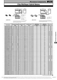
Trimmer Potentiometers (PDF: 1.4MB) - Murata
Trimmer Potentiometers (PDF: 1.4MB) - Murata
Trimmer Potentiometers (PDF: 1.4MB) - Murata

Create successful ePaper yourself
Turn your PDF publications into a flip-book with our unique Google optimized e-Paper software.
!Note • Please read rating and !CAUTION (for storage, operating, rating, soldering, mounting and handling) in this catalog to prevent smoking and/or burning, etc.<br />
• This catalog has only typical specifications. Therefore, please approve our product specifi cations or transact the approval sheet for product specifi cations before ordering.<br />
R50E.pdf<br />
Jul.23,2012<br />
1<br />
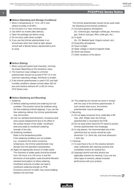
PVZ2/PVA2 Series Notice<br />
c Notice (Operating and Storage Conditions)<br />
1. Store in temperatures of -10 to +40°C and<br />
relative humidity of 30-85%.<br />
2. Do not store in or near corrosive gases.<br />
3. Use within six months after delivery.<br />
4. Open the package just before using.<br />
5. Do not store under direct sunlight.<br />
6. If you use the trimmer potentiometer in an<br />
environment other than listed at right, please<br />
consult with a <strong>Murata</strong> factory representative prior<br />
to using.<br />
The trimmer potentiometer should not be used under<br />
the following environmental conditions:<br />
(1) Corrosive gaseous atmosphere<br />
(Ex. Chlorine gas, Hydrogen sulfi de gas, Ammonia<br />
gas, Sulfuric acid gas, Nitric oxide gas, etc.)<br />
(2) In liquid<br />
(Ex. Oil, Medical liquid, Organic solvent, etc.)<br />
(3) Dusty/dirty atmosphere<br />
(4) Direct sunlight<br />
(5) Static voltage or electric/magnetic fi elds<br />
(6) Direct sea breeze<br />
(7) Other variations of the above<br />
c Notice (Rating)<br />
1. When using with partial load (rheostat), minimize<br />
the power depending on the resistance value.<br />
2. The maximum input voltage to a trimmer<br />
potentiometer should not exceed (P·R)^1/2 or the<br />
maximum operating voltage, whichever is smaller.<br />
3. If the trimmer potentiometer is used in DC and high<br />
humidity conditions, please connect wiper (#2) for<br />
plus and resistive element (#1 or #3) for minus.<br />
(PVZ Series only)<br />
c Notice (Soldering and Mounting)<br />
1. Soldering<br />
(1) Refl ow soldering method and soldering iron are<br />
available. This product cannot be soldered using<br />
the fl ow soldering method (dipping). If you use the<br />
fl ow soldering method, the trimmer potentiometer<br />
may not function.<br />
(2) Use our standard land dimension. Excessive land<br />
area causes displacement due to the effect of<br />
the surface tension of the solder. Insuffi cient<br />
land area leads to insuffi cient soldering<br />
strength of the chip.<br />
(3) Soldering conditions<br />
Refer to the temperature profi le.<br />
If the soldering conditions are not suitable,<br />
e.g., excessive time and/or excessive<br />
temperature, the trimmer potentiometer may<br />
deviate from the specifi ed characteristics.<br />
(4) Apply the appropriate amount of solder paste.<br />
The thickness of solder paste should be printed<br />
from 100 micro m to 150 micro m and the<br />
dimension of land pattern used should be <strong>Murata</strong>'s<br />
standard land pattern at refl ow soldering.<br />
Insuffi cient amounts of solder can lead to<br />
insuffi cient soldering strength on PCB.<br />
Excessive amounts of solder may cause bridging<br />
between the terminals.<br />
(5) The soldering iron should not come in contact<br />
with the case of the trimmer potentiometer. If<br />
such contact does occur, the trimmer<br />
potentiometer may be damaged.<br />
2. Mounting<br />
(1) Do not apply excessive force, preferably 4.9N<br />
max. (Ref. 500gf) when the trimmer<br />
potentiometer is mounted to the PCB.<br />
(2) Do not warp and/or bend the PC board to protect<br />
trimmer potentiometer from breakage.<br />
(3) In chip placers, the recommended size of the<br />
cylindrical pick-up nozzle should be outer<br />
dimension 1.5-1.8mm dia. and inner dimension<br />
1.3mm dia.<br />
3. Cleaning<br />
(1) In case there is fl ux on the resistive element,<br />
clean suffi ciently with cleaning solvents and<br />
completely remove all residual fl ux.<br />
(2) Isopropyl alcohol and ethyl alcohol are<br />
applicable solvents for cleaning. If you use any<br />
other types of solvents, please evaluate<br />
performance with your product.<br />
Continued on the following page.<br />
8