Trimmer Potentiometers (PDF: 1.4MB) - Murata
Trimmer Potentiometers (PDF: 1.4MB) - Murata
Trimmer Potentiometers (PDF: 1.4MB) - Murata

Create successful ePaper yourself
Turn your PDF publications into a flip-book with our unique Google optimized e-Paper software.
!Note • Please read rating and !CAUTION (for storage, operating, rating, soldering, mounting and handling) in this catalog to prevent smoking and/or burning, etc.<br />
• This catalog has only typical specifications. Therefore, please approve our product specifi cations or transact the approval sheet for product specifi cations before ordering.<br />
R50E.pdf<br />
Jul.23,2012<br />
SMD Open Type (PVZ2/A2/Z3)/SMD Sealed Type (PVM4A_C01 Series) Specifications and Test Methods<br />
The tests and measurements should be conducted under the conditions of 15 to 35°C of temperature, 25 to 75% of relative humidity and 86 to 106 kpa of<br />
atmospheric pressure unless otherwise specified. If questionable results occur that have been measured in accordance with the above-mentioned<br />
conditions, the tests and measurements should be conducted under the conditions of 25±2°C of temperature, 45 to 55% of relative humidity and 86 to<br />
106 kpa of atmospheric pressure.<br />
No.<br />
Item<br />
Test Methods<br />
1 Residual Resistance<br />
Position the contact arm at the extreme counterclockwise limit of mechanical travel and measure the resistance<br />
between the contact arm and the corresponding end terminal. Then, position the contact arm at the extreme<br />
clockwise limit of mechanical travel and measure the resistance between the contact arm and the corresponding end<br />
terminal. During this test, take suitable precautions to ensure that the rated current of the resistance element is not<br />
exceeded.<br />
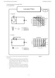
Contact resistance variation should be measured with the measuring circuit shown below, or its equivalent. The<br />
operating wiper should be rotated in both directions through 90% of the actual effective-electrical travel for a total of<br />
6 cycles.<br />
The rate of rotation of the operating wiper should be such that the wiper completes 1 count in determining whether or<br />
not a contact resistance variation is observed at least twice in the same location. The test current should follow the<br />
value given in Table 2 unless otherwise limited by the power rating.<br />
2 Contact Resistance<br />
3 Humidity Exposure<br />
4<br />
5 Humidity Load Life<br />
6 Load Life<br />
7 Temperature Cycle<br />
8<br />
High Temperature<br />
Exposure<br />
Temperature Coefficient of<br />
Resistance<br />
9 Rotational Life<br />
· PVZ/PVA2<br />
Standard Total<br />
Resistance R (ohm)<br />
100VRF10k<br />
10kVRF100k<br />
100kVR<br />
· PVM4ApppC01<br />
Standard Total<br />
Resistance R<br />
(ohm)<br />
RV100<br />
100FRF500<br />
500VRF1k<br />
1kVRF2k<br />
2kVRF50k<br />
Table 2: Test current for CRV<br />
The wiper contact point should be preset at about 50% position of effective rotational angle. After that, the<br />
potentiometer should be placed in a chamber at 40±2°C and 90 - 95% without loading for 500±12 hours.<br />
The resistance value should be measured after keeping the potentiometer in a room for 5±1/6 hours.<br />
The wiper contact point should be preset at about 50% position of effective rotational angle. After that, the<br />
potentiometer should be placed in a chamber at 70±2°C without loading for 500±12 hours. The resistance value<br />
should be measured after keeping the potentiometer in a room for 1.5±1/6 hours.<br />
The wiper contact point should be preset at about 50% position of effective rotational angle. After that, the<br />
potentiometer should be placed in a chamber at 40±2°C and 90 - 95% with loading the 1/2 rated voltage between<br />
#1 and #2 terminals, intermittently 1.5 hours ON and 0.5 hours OFF for 1000±12 hours.<br />
The resistance value should be measured after keeping the potentiometer in a room for 5±1/6 hours.<br />
The wiper contact point should be preset at about 50% position of effective rotational angle. After that, the<br />
potentiometer should be placed in a chamber at 70±2°C (50±2°C for PVZ) with loading the 1/2 rated voltage<br />
between #1 and #2 terminals, intermittently 1.5 hours ON and 0.5 hours OFF for 1000±12 hours. The resistance<br />
value should be measured after keeping the potentiometer in a room for 1 to 2 hours.<br />
The wiper contact point should be preset at about 50% position of effective rotational angle. After that, the<br />
potentiometer should be subjected to Table 3, Table 4 temperature for 5 cycles. The resistance value should be<br />
measured after keeping the potentiometer in a room for 1 to 2 hours.<br />
Sequence 1<br />
Temp. (°C) -25±3<br />
Time (min.) 30±3<br />
2<br />
+25±2<br />
10 max.<br />
Table 3: PVZ<br />
The trimmer potentiometer should be subjected to each of the following temperatures (see Table 5, Table 6) for 30<br />
to 40 minutes. The resistance value should be measured in the chamber.<br />
TCR=<br />
R2 – R1<br />
R1 (T2 – T1)<br />
T1 : Reference temperature in degrees celsius<br />
R1 : Resistance at reference temperature in ohm<br />
Sequence 1*<br />
Temp. (°C) +25±2<br />
Test<br />
Current<br />
20mA<br />
10mA<br />
4mA<br />
2mA<br />
1mA<br />
2<br />
-25±3<br />
Table 5: PVZ<br />
Note*: Norm temp.<br />
Test Current<br />
20mA max.<br />
1mA max.<br />
100μA max.<br />
Standard Total<br />
Resistance R<br />
(ohm)<br />
50kVRF200k<br />
200kVRF1M<br />
1MVRF2M<br />
2MVR<br />
3<br />
+85±3<br />
30±3<br />
Z 10 6 (ppm/°C)<br />
3*<br />
+25±2<br />
4<br />
+25±2<br />
10 max.<br />
4<br />
+85±3<br />
Test<br />
Current<br />
200μA<br />
100μA<br />
50μA<br />
30μA<br />
Constant Current<br />
Source<br />
(Test current<br />
shown in Table 2)<br />
Figure 1: CRV measuring circuit<br />
Sequence 1<br />
Temp. (°C) -55±3<br />
Time (min.) 30±3<br />
2<br />
+25±2<br />
10 max.<br />
3<br />
+125±3<br />
30±3<br />
Table 4: PVA2/PVM4A---C01<br />
T2 : Test temperature in degrees celsius<br />
R2 : Resistance at test temperature in ohm<br />
Sequence 1*<br />
Temp. (°C) +25±2<br />
2<br />
-55±3<br />
3*<br />
+25±2<br />
Table 6: PVA2/PVM4A---C01<br />
4<br />
+25±2<br />
10 max.<br />
4<br />
+125±3<br />
The wiper should be rotated over 90% of the effective rotational angle without loading at a speed of 10 cycles per<br />
minute, for 10 cycles continuously. The resistance value should be measured after keeping the potentiometer in a<br />
room for 10±5 minutes.<br />
#1<br />
Rx<br />
#3<br />
#2<br />
Calibration<br />
resistance<br />
Rx : <strong>Trimmer</strong> Potentiometer<br />
Oscilloscope bandwidth: 100Hz to 50kHz<br />
AC<br />
Amplifier<br />
Oscilloscope<br />
vertical<br />
entry<br />
45