Family Dollar - Master-Bilt
Family Dollar - Master-Bilt
Family Dollar - Master-Bilt

You also want an ePaper? Increase the reach of your titles
YUMPU automatically turns print PDFs into web optimized ePapers that Google loves.
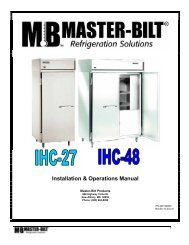
BLG/TLG-27, 48, 52, 74, 80<br />
2008 M Version<br />
Installation & Operations Manual<br />
<strong>Master</strong>-<strong>Bilt</strong> Products<br />
908 Highway 15 North<br />
New Albany, MS 38652<br />
Phone: (800) 684-8988<br />
PN 303-91000<br />
Rev:8-20-05<br />
Rev:8-23-06<br />
Rev:11-14-08
TABLE OF CONTENTS<br />
INTRODUCTION………………………………….……………………………………………………………………4<br />
STORE CONDITIONS…………………………….……………….…..…………………………………………….. 4<br />
WARNING LABELS AND SAFETY INSTRUCTIONS………..…..……………………………………………… 5<br />
PRE-INSTALLATION INSTRUCTIONS………………………..…..………………………………….…………… 6<br />
Inspection for Shipping Damage…………………………………………………………….……………... 6<br />
INSTALLATION INSTRUCTIONS………………………………………………………………………………….. 6<br />
General Instructions…………………………………………………………………………………………. 6<br />
MECHANICAL…… ..…………………………………………………………………………………………………..6<br />
ELECTRICAL….…………...…………………………………………………………………………………………..7<br />
Leg and Condensate Pan Installation……………………………………………………………………………. 7<br />
DOORS…….. ..…………....………………………………………………………………………………………….. 8<br />
ELECTRONIC REFRIGERATION CONTROL (DIXELL RX60C)…………………………………………….… 9<br />
Programming……………………………………………………………………………………………..…. 9<br />
List of Parameters………………………………………………………………………………………..….10<br />
SENSOR PROBE ……………………………………………………………………………… .………………..11<br />
CABINET COMPONENT AMP DRAW……………………………………………………………………………..11<br />
FINAL CHECK LIST…………………………………………………………………………………….…………….12<br />
SERVICE INSTRUCTIONS ………………………………………………………………………………………...12<br />
TEMPERATURE SENSOR, DEFROST HEATER AND FAN MOTOR REPLACEMENT…………………… 13<br />
MASTER-BILT PART NUMBERS …………………………………………………………………………..……. 14<br />
ACCESSORIES …………………………………………………………………………………………………….15<br />
SALE AND DISPOSAL ……………………………………………………………………………………………..15<br />
WIRING DIAGRAMS BLG/TLG………………………………………….……………………….………… …...16-20<br />
3
INTRODUCTION<br />
Thank you for purchasing a <strong>Master</strong>-<strong>Bilt</strong> cabinet. This manual contains important instructions for installing, using,<br />
and servicing a <strong>Master</strong>-<strong>Bilt</strong> BLG/TLG case. A parts list is included with this manual. Read all these documents<br />
carefully before installing or servicing your equipment.<br />
STORE CONDITIONS<br />
The <strong>Master</strong>-<strong>Bilt</strong> BLG/TLG cases are designed to operate in the controlled environment of an air-conditioned store.<br />
The store temperature should be at or below 75°F and a relative humidity of 55% or less. At higher temperature or<br />
humidity conditions, the performance of these cases may be affected and the capacity diminished.<br />
The <strong>Master</strong>-<strong>Bilt</strong> BLG/TLG should not be positioned where it is directly exposed to rays of sun or near a direct source<br />
of radiant heat or airflow. This will adversely affect the case and will result in poor performance.<br />
If this case is to be located against a wall, there should be at least 6” space between the wall and the back of the<br />
case. This space will allow for the circulation of air behind the case, which will prevent condensation on the exterior<br />
surfaces.<br />
NOTICE<br />
Read this manual before installing your cabinet. Keep the manual and refer to it before<br />
doing any service on the equipment. Failure to do so could result in personal injury or damage to the<br />
cabinet.<br />
DANGER<br />
Improper or faulty hook-up of electrical components on the refrigeration units can result in severe injury or<br />
death.<br />
All electrical wiring hook-ups must be done in accordance with all applicable local, regional or national<br />
standards.<br />
NOTICE<br />
Installation and service of the refrigeration and electrical components of the cabinet must be performed by<br />
a refrigeration mechanic and/or a licensed electrician.<br />
The portions of this manual covering refrigeration and electrical components contain technical instructions intended<br />
only for persons qualified to perform refrigeration and electrical work.<br />
This manual cannot cover every installation, use or service situation. If you need additional information, call or write<br />
us:<br />
Customer Service Department<br />
<strong>Master</strong>-<strong>Bilt</strong> Products<br />
Highway 15 North<br />
New Albany, MS 38652<br />
Phone (800) 684-8988<br />
Fax (800) 684-8988<br />
4
WARNING LABELS AND SAFETY INSTRUCTIONS<br />
This symbol is the safety-alert symbol. When you see this symbol on your cabinet or in this<br />
manual, be alert to the potential for personal injury or damage to your equipment.<br />
Be sure you understand all safety messages and always follow recommended precautions and safe operating<br />
practices.<br />
NOTICE TO EMPLOYERS<br />
You must make sure that everyone who installs, uses or services your cabinet is thoroughly familiar with all<br />
safety information and procedures.<br />
Important safety information is presented in this section and throughout the manual. The following signal words are<br />
used in the warnings and safety messages:<br />
DANGER:<br />
Severe injury or death will occur if you ignore the message.<br />
WARNING: Severe injury or death can occur if you ignore the message.<br />
CAUTION: Minor injury or damage to your cabinet can occur if you ignore the message.<br />
NOTICE: This is important installation, operation or service information. If you ignore the<br />
message, you may damage your cabinet.<br />
The warning and safety labels shown throughout this manual are placed on your <strong>Master</strong>-<strong>Bilt</strong> Products<br />
cabinet at the factory. Follow all warning label instructions. If any warning or safety labels become lost or<br />
damaged, call your customer service department at (800) 684-8988 for replacements.<br />
CAUTION!<br />
GROUND REQUIRED<br />
FOR SAFE OPERATION<br />
This label is located on top of the electrical control<br />
label and on the wiring channel.<br />
This label is attached to the cabinet power cord<br />
on models with a power cord.<br />
5
PRE-INSTALLATION INSTRUCTIONS<br />
INSPECTION FOR SHIPPING DAMAGE<br />
You are responsible for filing all freight claims with the delivering truck line. Inspect all cartons and crates for<br />
damage as soon as they arrive. If damage is noted to shipping crates or cartons or if a shortage is found, note this<br />
on the bill of lading (all copies) prior to signing.<br />
If damage is discovered when the cabinet is uncrated, immediately call the delivering truck line and follow up the call<br />
with a written report indicating concealed damage to your shipment. Ask for an immediate inspection of your<br />
concealed damage item. Crating material must be retained to show the inspector from the truck line.<br />
INSTALLATION INSTRUCTIONS<br />
GENERAL INSTRUCTIONS<br />
1. Be sure the equipment is properly installed by competent service people.<br />
2. Keep the equipment clean and sanitary so it will meet your local sanitation codes. Clean the cabinet with a mild<br />
detergent and water, then rinse.<br />
3. Rotate your stock so that older stock does not accumulate. This is especially important for ice<br />
cream. A "First-In, First-Out" rotation practice will keep the products in good salable condition.<br />
4. Do not place product in the case when it is soft or partially thawed. Also, product should not be put in the case for<br />
at least 6 hours after it is started.<br />
5. Stock cases as quickly as possible, exposing only small quantities to store temperatures for short periods of<br />
time.<br />
6. When replacing burned out fluorescent tubes, be sure that the electrical power to the lighting circuit is turned off.<br />
NOTICE TO STORE OWNERS / MANAGERS<br />
Moisture or liquid around or under the cabinet is a potential slip/fall hazard for persons walking by or<br />
working in the general area of the cabinet. Any cabinet malfunction or housekeeping problem that creates a<br />
slip/fall hazard around or under the cabinet should be corrected immediately.<br />
If moisture or liquid is observed around or under a <strong>Master</strong>-<strong>Bilt</strong> cabinet, an immediate investigation should be made<br />
by qualified personnel to determine the source of the moisture or liquid. The investigation should determine if the<br />
cabinet is malfunctioning or if there is a drainpipe leaking.<br />
MECHANICAL<br />
Remove front grille and check refrigeration lines to see that they are free (not touching each other or compressor).<br />
Spin condenser fan blade to see that it is free.<br />
Remove cabinet from crate base and slide into location. Cabinet must be level from side to side and front to back for<br />
correct draining of coil pan and for self-closing doors to operate correctly. Allow minimum of 4” between back of<br />
cabinet and wall and between top of cabinet and ceiling for proper condensing unit air circulation.<br />
To comply with Sanitation requirements the cabinet must be mounted on legs (6” high min.) or casters or the base<br />
must be sealed to the floor (BLG) with an N.S.F. listed silicone sealant.<br />
6
ELECTRICAL<br />
WARNING<br />
Before servicing electrical components in the case or the doors or door frames make sure all power to case<br />
is off. Always use a qualified technician.<br />
Check voltage and amps drawn on (Page 17-20) to determine proper line and fuse or circuit breaker size. Check<br />
power supply for low voltage. If voltage reads “230” with no load, and it drops below “207” when the compressor tries<br />
to start, it is an indication of too small supply wiring or too long to run.<br />
It is recommended that a separate circuit be run for each cabinet to prevent another appliance blowing the fuse or<br />
breaker, causing loss of product.<br />
IMPORTANT<br />
Models (2 and 3 door low temp) are pre-wired internally with a 208-230V NEMA L14-20P plug<br />
and should only be plugged into a NEMA L14-20P recepticle. See wiring diagrams on<br />
page 19-21. The cabinet should be grounded.<br />
LEG AND CONDENSATE PAN INSTALLATION FOR TOP MOUNT CABINETS ONLY<br />
1. Screw legs into existing crate mounting holes.<br />
2. Before moving cabinet into place, remove the<br />
condensate pan from the top unit compartment.<br />
3. Using the two screws supplied with the pan, attach<br />
the pan to the back of the cabinet at the two holes<br />
near the bottom of the plastic drain line. Be sure<br />
pan is NOT located directly under cabinet. When<br />
the pan is attached, feeds drain line into the open<br />
hole in screen and clamp the heater conduit to the<br />
back of the cabinet. Due to this condensate pan,<br />
this case must be a minimum of 6” from the wall.<br />
4. If cabinet must be located next to wall, the pan can<br />
be located under the cabinet. When this is done,<br />
steam will accumulate on the bottom of the cabinet<br />
if there is not adequate ventilation, and rusting of<br />
the bottom of the cabinet<br />
will occur.<br />
7
DOORS<br />
The BLG/TLG cabinets have Anthony glass doors<br />
that are equipped with a patented Torque<strong>Master</strong><br />
hinge system. The doors are easily adjusted using<br />
a flathead screwdriver (Fig.3).<br />
* The tension needs to be checked and set when<br />
first install.<br />
Leveling Adjustment<br />
Torque Adjustment<br />
To remove the door shipping clamps,<br />
remove the 4 shipping screws from the grill and<br />
remove the screws from the clamps (Fig.4), and<br />
replace grill.<br />
Figure 3<br />
Figure 4<br />
8
MASTER-BILT ELECTRONIC REFRIGERATION CONTROL<br />
OPERATION<br />
Compressor When power is first turned on to the control, the LED indicator under COMP on the display starts<br />
blinking. After one-minute delay the compressor comes on. The COMP LED indicator stays on while compressor<br />
relay is energized. Display will show actual box temperature. Figure 4 is the display layout.<br />
The compressor will be cycled off when the actual box temperature reaches its set point. The COMP indicator will<br />
be off.<br />
Fig. 4 – Display Lay-out<br />
Fan The fans will run constantly except when a defrost is initiated, or when the evaporator temp is above the<br />
30 o F. When in defrost mode the fan is off until the end of the defrost and the 2 minute drip time has passed. There<br />
is 4 minutes delay after a defrost before the fan comes on. The difference of the evaporator and room temperature<br />
of more than 9 o F will override the fan delay. FAN LED indicator is on while FAN relay is energized.<br />
Defrost The control uses time defrost with 4 defrost per day. A programmed “HOT-KEY” has to be used to<br />
re-set the defrost scheme for special applications. During defrost the display will show dEF and the LED indicator<br />
under DEF in on. The control begins timing the defrost when power is turned on. Four defrost per day means it will<br />
occur every 6 hours. To have defrost occur at 8am, 2pm, 8pm, and 2am then power up at one of these four times.<br />
MANUAL DEFROST<br />
1. Push this DEFROST key for more than 2 seconds and a manual defrost will start.<br />
2. While in defrost, Push and hold the DEFROST key for more than 5 seconds and the controller<br />
will end the defrost cycle. The controller will then enter drip mode for 2 minutes. The DEF led is flashing in<br />
drip mode.<br />
HOW TO SEE THE SETPOINT (Box temperature cut-out)<br />
1. Push and immediately release the SET key: the display will show the Set<br />
point value;<br />
2. Push and immediately release the SET key or wait for 5 seconds to display the probe value<br />
(actual box temperature) again.<br />
HOW TO CHANGE THE SETPOINT<br />
1. Push the SET key for more than 2 seconds to change the Set point value;<br />
2. The value of the set point will be displayed and the LED under COMP starts blinking;<br />
3. To change the Set value push the UP ▲ or DOWN▼ arrows within 10s.<br />
To memorize the new set point value push the SET key again or wait 10s.<br />
9
HOW TO CHANGE a parameter value<br />
1. Enter the Programming mode by pressing the SET and DOWN ▼ keys for 3 seconds (LEDs<br />
under DEF and COMP start blinking).<br />
2. Select the required parameter by pushing the UP ▲ or DOWN▼ arrows<br />
3. Press the “SET” key to display its value (now only the COMP LED is blinking)<br />
4. Use “UP” or “DOWN” to change its value<br />
5. To exit: Press SET + UP ▲ or wait 15s without pressing a key.<br />
NOTE 1: The set value is stored even when the procedure is exited by waiting the time-out to expire.<br />
NOTE 2: <strong>Master</strong>-<strong>Bilt</strong>’s SETPOINT is set at a recommended –10°F at the factory for low temperature(LT) and<br />
+35 o F for medium temperature(MT) application.<br />
NOTE 3: To scroll down the parameters without changing them, press the DOWN button.<br />
LIST OF PARAMETERS<br />
Here is a list of the parameters the value of which can be changed in the programming mode, as well as their ranges.<br />
<strong>Master</strong>-<strong>Bilt</strong>’s<br />
Display<br />
Parameter<br />
Description<br />
Range Setting<br />
Symbol<br />
Temperature Set Point<br />
Temperature Differential<br />
Maximum Temperature Alarm<br />
Minimum Temperature Alarm<br />
Temperature Alarm Delay<br />
Room Probe display<br />
Evaporator Probe Display<br />
Set<br />
Hy<br />
ALU<br />
ALL<br />
When this temperature is<br />
reached the compressor LED<br />
will be off<br />
BLG<br />
-16 to 5°F -10°F or -15°F<br />
Cut-out temperature is Set + Hy 1 to 255°F 10<br />
230°F 15<br />
-58°F -25<br />
Ald 0 to 255 min 30<br />
dP1<br />
dP2<br />
ALARM SIGNALS<br />
Message Cause Outputs<br />
“P1” Room probe failure Compressor output time, 6 min on, 4 min off<br />
“P2” Evaporator probe failure Defrost end is timed<br />
“HA”<br />
Maximum temperature alarm<br />
Outputs unchanged.<br />
“LA” Minimum temperature alarm Outputs unchanged.<br />
NOTE:<br />
Probe alarms “P1” and “P2” start some seconds after the fault in the related probe; they automatically stop<br />
some seconds after the probe restarts normal operation. Check connections before replacing the probe.<br />
Temperature alarms “HA” and “LA” automatically stop as soon as the thermostat temperature returns to<br />
normal values and when defrost starts.<br />
10
ELECTRICAL CONNECTIONS<br />
The controller is provided with screw terminal block to connect cables with a cross section up to 2,5 mm 2 . Before<br />
connecting cables make sure the power supply complies with the control’s requirements. Separate the probe cables<br />
from the power supply cables, from the outputs and the power connections. Do not exceed the maximum current<br />
allowed on each relay, in case of heavier loads use a suitable external relay.<br />
PROBE CONNECTIONS<br />
The probes shall be mounted with the bulb upwards to prevent damages due to casual liquid infiltration. It is<br />
recommended to place the thermostat probe away from air streams to correctly measure the average room<br />
temperature. Place the defrost termination probe among the evaporator fins in the coldest place, where most ice is<br />
formed, far from heaters or from the warmest place during defrost, to prevent premature defrost termination.<br />
BLG/TLG CABINET COMPONENT AMP DRAW<br />
ITEM<br />
PART VOLTAGE<br />
AMPS AT AMPS AT<br />
NO. RATING CABINET 208 VOLTS 230 VOLTS NOTES<br />
Coil Defrost Heater 17-09408 230 V BLG/TLG-48, 52 3.9 4.3 Check Red or Black Leg<br />
Coil Defrost Heater 17-01311 230 V BLG/TLG-74, 80 6.3 7 Check Red or Black Leg<br />
Condensate Heater 230 V BLG-48, 52, 74, 80 1.2 1.3 Check Red or Black Leg<br />
Condensate Heater 201I130 230 V TLG-48, 52, 74, 80 1.2 1.3 Check Red or Black Leg<br />
Door Frame Heater 17-09419 115 V BLG/TLG-48, 52, 74, 80 .33 ea .37 ea Check Black Leg<br />
Door 31-02602 120V BLG/TLG-48, 74 .55 ea .60 ea Check Black Leg<br />
Door 31-02603 120V BLG/TLG-48 .55 ea .60 ea Check Black Leg<br />
Door 31-02604 120V BLG/TLG-52, 80 .76 ea .84 ea Check Black Leg<br />
Door 31-02605 120V BLG/TLG-52 .76 ea .84 ea Check Black Leg<br />
Drain Heater 17-00404 115 V BLG/TLG-48, 52, 74, 80 0.05 0.06 Check Black Leg<br />
ITEM<br />
PART VOLTAGE<br />
AMPS AT AMPS AT<br />
NO. RATING CABINET 104 VOLTS 115 VOLTS NOTES<br />
Coil Defrost Heater 17-09407 120 V BLG/TLG-27 4.3 4.8 Check Black Leg<br />
Condensate Heater A321-130 115 V BLG-27 2.3 2.6 Check Black Leg<br />
Condensate Heater 323I130 115 V TLG-27 2.3 2.6 Check Black Leg<br />
Door Frame Heater 17-09419 115 V BLG/TLG-27 0.33 0.37 Check Black Leg<br />
Door 31-02600 120V BLG/TLG-27 .81 ea .90 ea Check Black Leg<br />
Drain Heater 17-00404 115 V BLG/TLG-27 0.05 0.06 Check Black Leg<br />
11
FINAL CHECK LIST<br />
A. Check operating pressures.<br />
B. Check electrical requirements of unit to<br />
supply voltage.<br />
C. Set temperature control for desired<br />
temperature range.<br />
D. Check sight glass for proper refrigerant<br />
charge, if provided.<br />
E. Check system for proper defrost settings and<br />
operation.<br />
F. Check condensing unit for vibrating or<br />
rubbing tubing. Dampen and clamp as<br />
required.<br />
G. All valves should be completely opened<br />
counter-clockwise.<br />
H. Check packing nuts on all service valves.<br />
I. Replace all service valve caps and latch unit<br />
covers.<br />
J. Check and set the door tension at the Torque<br />
Adjustment.<br />
SERVICE INSTRUCTION<br />
1. High head pressure and high back pressure:<br />
A. Condenser coil clogged or restricted<br />
B. Condenser fan motor defective.<br />
C. Air discharge in rear of cabinet restricted.<br />
2. Low back pressure and low head pressure:<br />
A. Restriction in system.<br />
B. Refrigerant undercharged.<br />
C. Leak in system<br />
3. Pressure normal – cabinet warm:<br />
A. Coil blocked with frost (see #4).<br />
B. Refrigerant undercharged.<br />
C. Control set too warm.<br />
4. Cabinet not cycling – coil blocked with frost:<br />
A. Defective temperature controller.<br />
B. Refrigerant overcharged.<br />
C. Location too hot.<br />
D. Condenser clogged.<br />
E. Condenser fan motor defective.<br />
F. Defrost heater not operating.<br />
5. Copressor starts and runs – but cycles on overload:<br />
A. Low voltage<br />
B. Relay defective.<br />
C. Overload defective.<br />
D. High head pressure (see #1).<br />
12
Temperature sensor, defrost heater and fan motor replacement<br />
Before making any change, technician should:<br />
1. Disconnect power to the cabinet<br />
2. Remove screws from venturi and pull down<br />
To change a temperature sensor (cabinet zone sensor or defrost termination sensor), simply disconnect the sensor<br />
wires from the controller and replace the new sensor in the original position. Use plastic tie to tighten the zone<br />
sensor. Insert the sensor for defrost termination firmly into the evaporator coil, in between the fins. Make sure the<br />
sensor wires do not touch or are not close to any heater rods.<br />
To change defrost heater – remove screws from drain pan and pull down – remove screws from coil mounting<br />
straps – spring straps open – remove heater shield – pull heater out of slots in coil fins.<br />
To change fan motor – disconnect fan motor leads – remove screws from fan guards and motor mounts.<br />
13
MASTER-BILT PART LIST<br />
The table below gives <strong>Master</strong>-<strong>Bilt</strong> part numbers. Use this chart when ordering replacement parts for your<br />
BLG/TLG cabinets. Always Advise Cabinet Serial Number When Ordering Parts<br />
BLG/TLG- BLG/TLG- BLG/TLG- BLG/TLG- BLG/TLG-<br />
Description<br />
27HD 48HD 52HD 74HD 80HD<br />
Ballast 23-01717 23-01717 23-01717 23-01717 23-01717<br />
Bulb 23-01716 23-01716 23-01716 23-01716 23-01716<br />
Bulb Holder Bottom 23-01698 23-01698 23-01698 23-01698 23-01698<br />
Bulb Holder Top 23-01699 23-01699 23-01699 23-01699 23-01699<br />
Bulb Shield Inner 23-01464 23-01464 23-01464 23-01464 23-01464<br />
Bulb Shield Outer 25-01311 25-01311 25-01311 25-01311 25-01311<br />
Coil Defrost Heater 17-09407 17-09408 17-09408 17-01311 17-01311<br />
Compressor 03-14799 03-14968 03-14968 03-14973 03-14973<br />
Compressor Contactor 19-13936 19-13934 19-13934 19-13934 19-13934<br />
Compressor Relay 03-14980 03-14979 03-14977 03-14977<br />
Compressor Run Capacitor 03-14978 03-14978 03-14975 03-14975<br />
Compressor Start Capacitor 03-14979 03-14979 03-14976 03-14976<br />
Compressor Switch 19-13118 19-13118 19-13118 19-13118 19-13118<br />
Condensate Heater “TLG” 17-00399 17-09412 17-09412 17-09412 17-09412<br />
Condensate Heater<br />
Electric, TLG<br />
323I130 323I130 323I130 323I130 323I130<br />
Condensate Heater, BLG<br />
A321-130 17-00421 17-00421 17-00421 17-00421<br />
Electric (Optional)<br />
Condenser Coil 07-13391 07-13090 07-13090 07-13090 07-13090<br />
Condenser Fan Blade 15-13093 15-13093 15-13093 15-13093 15-13093<br />
Condenser Fan Motor 13-00311 13-01283 13-01283 13-01283 13-01283<br />
Door Frame Heater 17-09419 17-09419 17-09419 17-09419 17-09419<br />
Door-L.H. (Black) 31-02600 31-02602 31-02604 31-02602 31-02604<br />
Door-R.H. 31-02603 31-02605<br />
Drain Heater 17-00404 17-00404 17-00404 17-00404 17-00404<br />
Drier 09-09171 09-09711 09-09711 09-09711 09-09711<br />
Electronic Controller 19-14085 19-14085 19-14085 19-14085 19-14085<br />
Evaporator Coil 07-13288 07-13289 07-13289 07-13290 07-13290<br />
Evaporator Fan Blade 15-13106 15-13106 15-13106 15-13106 15-13106<br />
Evaporator Fan Guard 25-01324 25-01324 25-01324 25-01324 25-01324<br />
Evaporator Fan Motor 13-13181 13-13182 13-13182 13-13182 13-13182<br />
Expansion Valve 09-09825 09-09758 09-09758 09-09759 09-09759<br />
Female Door Plug 21-00568 21-00568 21-00568 21-00568 21-00568<br />
Female Plug 21-00577 21-00577 21-00577 21-00577 21-00577<br />
Front Control 19-13897 19-13897 19-13897 19-13897 19-13897<br />
Heater Safety Control 19-01164 19-01164 19-01164 19-01164 19-01164<br />
Leg (TLG only) 27-00558 27-00558 27-00558 27-00558 27-00558<br />
Leg Leveler 27-00592 27-00592 27-00592 27-00592 27-00592<br />
Light Switch 23-50793 23-50793 23-50793 23-50793 23-50793<br />
Sight Glass<br />
Temperature Sensor (2) 19-13932 19-13932 19-13932 19-13932 19-13932<br />
Terminal Block 19-01091 19-01091 19-01091 19-01091<br />
14
Accessories (Includes HD Models)<br />
BLG/TLG BLG/TLG BLG/TLG BLG/TLG BLG/TLG<br />
Description 27HD 48HD 52HD 74HD 80HD<br />
Baskets (Cantilever)<br />
20” X 22” X 5”<br />
33-01458 33-01458<br />
Baskets(Conventional)<br />
22”X 22-3/4”X 5”<br />
33-01419 33-01419<br />
Baskets(Conventional)<br />
24-3/4”X22”X5”<br />
33-01376 33-01376<br />
Casters (4) 3” Diameter A20011140 A200-11140 A200-11140<br />
Casters (6) 3” Diameter A212-11140 A212-11140<br />
Legs 6” A20011170 A200-11170 A200-11170 A212-11170 A212-11170<br />
Shelves (Cantilever) 33-01473 33-01474 33-01475 33-01474 33-01475<br />
Shelve, Bottom 33-01402 33-01453 33-01448 33-01453 33-01448<br />
Shelving Clips (4) 33-01011 33-01011 33-01011 33-01011 33-01011<br />
SALE AND DISPOSAL<br />
OWNER RESPONSIBILITY<br />
If you sell or give away your <strong>Master</strong>-<strong>Bilt</strong> cabinet you must make sure that all safety labels and the Installation -<br />
Service Manual are included with it. If you need replacement labels or manuals, <strong>Master</strong>-<strong>Bilt</strong> will provide them free.<br />
Contact the customer service department at <strong>Master</strong>-<strong>Bilt</strong> at (800) 684-8988.<br />
The customer service department at <strong>Master</strong>-<strong>Bilt</strong> should be contacted at the time of sale or disposal of your cabinet<br />
so records may be kept of its new location.<br />
15