Installation & Operations Manual - Master-Bilt
Installation & Operations Manual - Master-Bilt
Installation & Operations Manual - Master-Bilt

You also want an ePaper? Increase the reach of your titles
YUMPU automatically turns print PDFs into web optimized ePapers that Google loves.
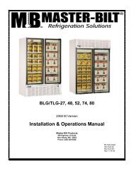
<strong>Installation</strong> & <strong>Operations</strong> <strong>Manual</strong><strong>Master</strong>-<strong>Bilt</strong> Products908 Highway 15 NorthNew Albany, MS 38652Phone: (800) 684-8988PN 297-90000Rev05-10-04 LN1
TABLE OF CONTENTSINTRODUCTION………………………………….……………………………………………………………………4STORE CONDITIONS…………………………….……………….…..…………………………………………….. 4WARNING LABELS AND SAFETY INSTRUCTIONS………..…..……………………………………………… 5PRE-INSTALLATION INSTRUCTIONS………………………..…..………………………………….…………… 6Inspection for Shipping Damage…………………………………………………………….……………...6INSTALLATION INSTRUCTIONS………………………………………………………………………………….. 6General Instructions…………………………………………………………………………………………. 6Mechanical ..…………………………………………………………………………………………………..6Electrical…………...…………………………………………………………………………………………..7Leg and Condensate Pan <strong>Installation</strong>..……………………………………………………………………..8SERVICE INSTRUCTIONS …………………………………………………………………………………………8TEMPERATURE SENSOR, DEFROST HEATER AND FAN MOTOR REPLACEMENT……………………. 8ELECTRONIC REFRIGERATION CONTROL (ERC).………………………………………………………….…9FINAL CHECK LIST…………………………………………………………………………………….…………….14SENSOR PROBE ………………………………………………………………………………….……………….14MASTER-BILT PART NUMBERS ……………………………………………………………………………….. 15ACCESSORIES………………………………………………………………………………………………………. 16SALE AND DISPOSAL …………………………………………………………………………………………….16WIRING DIAGRAMS IHC………………………………………….……………………….………………………...173
INTRODUCTIONThank you for purchasing a <strong>Master</strong>-<strong>Bilt</strong> cabinet. This manual contains important instructions for installing, using, andservicing a <strong>Master</strong>-<strong>Bilt</strong> IHC case. A parts list is included with this manual. Read all these documents carefully beforeinstalling or servicing your equipment.STORE CONDITIONSThe <strong>Master</strong>-<strong>Bilt</strong> IHCcases are designed to operate in the controlled environment of an air-conditioned store. The storetemperature should be at or below 75°F and a relative humidity of 55% or less. At higher temperature or humidityconditions, the performance of these cases may be affected and the capacity diminished.The <strong>Master</strong>-<strong>Bilt</strong> IHCshould not be positioned where it is directly exposed to rays of sun or near a direct source of radiantheat or airflow. This will adversely affect the case and will result in poor performance.If this case is to be located against a wall, there should be at least 4” space between the wall and the back of the case.This space will allow for the circulation of air behind the case, which will prevent condensation on the exterior surfaces.NOTICERead this manual before installing your cabinet. Keep the manual and refer to it beforedoing any service on the equipment. Failure to do so could result in personal injury or damage to the cabinet.DANGERImproper or faulty hook-up of electrical components on the refrigeration units can result in severe injury ordeath.All electrical wiring hook-ups must be done in accordance with all applicable local, regional or nationalstandards.NOTICE<strong>Installation</strong> and service of the refrigeration and electrical components of the cabinet must be performed by arefrigeration mechanic and/or a licensed electrician.The portions of this manual covering refrigeration and electrical components contain technical instructions intendedonly for persons qualified to perform refrigeration and electrical work.This manual cannot cover every installation, use or service situation. If you need additional information, call or write us:Customer Service Department<strong>Master</strong>-<strong>Bilt</strong> ProductsHighway 15 NorthNew Albany, MS 38652Phone (800) 684-8988Fax (800) 684-89884
WARNING LABELS AND SAFETY INSTRUCTIONSThis symbol is the safety-alert symbol. When you see this symbol on your cabinet or in thismanual, be alert to the potential for personal injury or damage to your equipment.Be sure you understand all safety messages and always follow recommended precautions and safe operatingpractices.NOTICE TO EMPLOYERSYou must make sure that everyone who installs, uses or services your cabinet is thoroughly familiar with allsafety information and procedures.Important safety information is presented in this section and throughout the manual. The following signal words areused in the warnings and safety messages:DANGER:Severe injury or death will occur if you ignore the message.WARNING: Severe injury or death can occur if you ignore the message.CAUTION: Minor injury or damage to your cabinet can occur if you ignore the message.NOTICE: This is important installation, operation or service information. If you ignore themessage, you may damage your cabinet.The warning and safety labels shown throughout this manual are placed on your <strong>Master</strong>-<strong>Bilt</strong> Products cabinetat the factory. Follow all warning label instructions. If any warning or safety labels become lost or damaged,call your customer service department at (800) 684-8988 for replacements.CAUTION!GROUND REQUIREDFOR SAFE OPERATIONThis label is attached to the cabinet power cordlabel and on the wiring channel.This label is located on top of the electrical controlon models with a power cord.5
PRE-INSTALLATION INSTRUCTIONSINSPECTION FOR SHIPPING DAMAGEYou are responsible for filing all freight claims with the delivering truck line. Inspect all cartons and crates for damageas soon as they arrive. If damage is noted to shipping crates or cartons or if a shortage is found, note this on the bill oflading (all copies) prior to signing.If damage is discovered when the cabinet is uncrated, immediately call the delivering truck line and follow up the callwith a written report indicating concealed damage to your shipment. Ask for an immediate inspection of your concealeddamage item. Crating material must be retained to show the inspector from the truck line.INSTALLATION INSTRUCTIONSGENERAL INSTRUCTIONS1. Be sure the equipment is properly installed by competent service people.2. Keep the equipment clean and sanitary so it will meet your local sanitation codes. Clean the cabinet with a milddetergent and water, then rinse.3. Rotate your stock so that older stock does not accumulate. This is especially important for icecream. A "First-In, First-Out" rotation practice will keep the products in good salable condition.4. Do not place product in the case when it is soft or partially thawed. Also, product should not be put in the case for atleast 6 hours after it is started.5. Stock cases as quickly as possible, exposing only small quantities to store temperatures for short periods of time.6. When replacing burned out fluorescent tubes, be sure that the electrical power to the lighting circuit is turned off.NOTICE TO STORE OWNERS / MANAGERSMoisture or liquid around or under the cabinet is a potential slip/fall hazard for persons walking by or workingin the general area of the cabinet. Any cabinet malfunction or housekeeping problem that creates a slip/fallhazard around or under the cabinet should be corrected immediately.If moisture or liquid is observed around or under a <strong>Master</strong>-<strong>Bilt</strong> cabinet, an immediate investigation should be made byqualified personnel to determine the source of the moisture or liquid. The investigation should determine if the cabinetis malfunctioning or if there is a drainpipe leaking.MECHANICALRemove front grille and check refrigeration lines to see that they are free (not touching each other or compressor).Spin condenser fan blade to see that it is free.Check that all service valves (2) are open. Cut compressor hold-down strap and remove. The springs are secured forshipping by either tightening bolts or shipping strap. Remove the strap or loosen the hold-down bolts so that thecompressor floats freely. Check all refrigeration lines and electrical conduit for rubbing or chaffing, paying particularattention to area where lines enter the cabinet.6
Remove cabinet from crate base and slide into location. Cabinet must be level from side to side and front to back forcorrect draining of coil pan and for self-closing doors to operate correctly. Allow minimum of 4” between back of cabinetand wall and between top of cabinet and ceiling for proper condensing unit air circulation.To comply with Sanitation requirements the cabinet must be mounted on legs (6” high min.) or casters or the base mustbe sealed to the floor with an N.S.F. listed silicone sealant.To comply with UL requirements the cabinet must have a minimum clearance of 4” at the top, 6” at the rear and 0” ateach side.ELECTRICALWARNINGBefore servicing electrical components in the case or the doors or door frames make sure all power to case isff. Always use a qualified technician.Check voltage and amps drawn on (Page 17) to determine proper line and fuse or circuit breaker size. Check powersupply for low voltage. If voltage reads “230” with no load, and it drops below “207” when the compressor tries to start, itis an indication of too small supply wiring or too long to run.It is recommended that a separate circuit be run for each cabinet to prevent another appliance blowing the fuse orbreaker, causing loss of product.The cabinet should be grounded.LOW TEMPERATURE FREEZERS – “IHC” ModelsThe IHC has a power cord (15A, 230 Volt) on top of the cabinet at the right rear for connection to power. On initialstart-up the evaporator fan motors will not start and you cannot initiate a defrost until the evaporator coil temperaturehas lowered to 30°F. This is due to the thermostat. Also, the cabinet comes with a non-adjustable “Front” control tokeep the mullion heaters off until the cabinet temperature has lowered to 10°F.7
LEG AND CONDENSATE PANINSTALLATION FOR TOP MOUNTCABINETS ONLY1. Screw legs into existing crate mountingholes.2. Mount pan and bracket assembly to rear ofcabinet with 2 large sheet metal screws(supplied). Be sure pan is located directlyunder cabinet drain.SERVICE INSTRUCTIONS1. High head pressure and high back pressure:A. Condenser coil clogged or restrictedB. Condenser fan motor defective.C. Air discharge in rear of cabinet restricted.2. Low back pressure and low head pressure:A. Restriction in system.B. Refrigerant undercharged.C. Leak in system3. Pressure normal – cabinet warm:A. Coil blocked with frost (see #4).B. Refrigerant undercharged.C. Control set too warm.4. Cabinet not cycling – coil blocked with frost:A. Defective temperature controller.B. Refrigerant overcharged.C. Location too hot.D. Condenser clogged.E. Condenser fan motor defective.F. Defrost heater not operating.5. Compressor starts and runs – but cycles on overload:A. Low voltageB. Relay defective.C. Overload defective.D. High head pressure (see #1).8
Temperature sensor, defrost heater and fan motor replacementBefore making any change, technician should:1. Disconnect power to the cabinet2. Remove screws from venturi and pull downTo change a temperature sensor (cabinet zone sensor or defrost termination sensor), simply disconnect the sensorwires from the controller and replace the new sensor in the original position. Use plastic tie to tighten the zone sensor.Insert the sensor for defrost termination firmly into the evaporator coil, in between the fins. Make sure the sensor wiresdo not touch or are not close to any heater rods.To change defrost heater – remove screws from drain pan and pull down – remove screws from coil mounting straps –spring straps open – remove heater shield – pull heater out of slots in coil fins.To change fan motor – disconnect fan motor leads – remove screws from fan guards and motor mounts.ERC 2 – ELECTRONIC REFRIGERATION CONTROLProgrammingThe ERC 2 control initially powers up displaying 12:00 AM otherwise it will show the last configuredselection (time or temperature). If a power outage occurs during normal operation, the control will maintainthe correct time-of-day using a capacitor (batteries are not required). The time will be maintained for up to100 hours when the capacitor is fully charged.To initiate a <strong>Manual</strong> Defrost, press and hold the MAN DEF key for 3 seconds.There are two levels of programming in the ERC 2. The first level of security will enable the user to set twoparameters: Time-of-day (CLoC) and Set point temperature (SEt). The other level allows access to theother parameters.Three buttons are used for the programming: SET, UP and DOWNTo access the pushbuttons on the ERC2,flip up the front cover using the tabs onthe side of the cover as shown.9
Alarm Delay ALrd Time delay beforethe alarm goes offafter temperaturefall off the two alarmset pointsNumber ofDefrostsDefrost StartTimeDefrostDurationnodFdEF1-8dEFdNumber of defrostsper dayStart time of eachdefrostDefrost durationtime(back-up for defrostterminationtemperature)Fan Delay FAnd Delay time for thefan after defrost(back-up forfancut-intemperature)Range: from 0 to 59 min 30from 0 to 8 (0 means 1 defrost 3every48 hours)Hour and minute selectable (def0 default = 1AM)(dEF1 default = 6 AM), (dEF2 default = 2 PM),(dEF3 default = 10 PM), (dEF4 default = 12 AM),(dEF5 default = 3 PM), (dEF6 default = 3 AM),(dEF7 default = 9 PM), (dEF8 default = 9 AM)Range: from 0 min to 4 hours 35Range: from 0 to 15 min 2Pump Down Pudn Pump down duration Range: from 0 to 59 min 0Drip Time driP Drip time duration Range: from 0 to 59 min 2SetpointDifferentialdiF°Range: from 1 to 25°5° FTemperatureInitiatedDefrostDefrostTerminationTemperatureFan Cut-InTemperatureLowTemperatureAlarmHighTemperatureAlarmtdEFdEF°FAn°ALLoALHiCut-in temperaturedifferential Note:cut-in is cut-out plusdifferentialTemperature thatwill initiate adefrost cycleTemperature in theevaporator that willterminate the defrostcycleTemperature in theevaporator that willturn the fan on afterdefrostLow temperaturesetpoint that willmake the alarm gooff and the errormessage appear onthe displayHigh temperaturesetpoint that willmake the alarm gooff and the errormessage appear onthe displayRange: from – 40 to 40°For – 40 to 4°CRange: from 0 to 75°For –18 to 25°CRange: from – 40 to 60°For – 40 to 23°CRange: from – 40 to 83°For – 40 to 23°CRange: from – 40 to83°F or –40 to 23°C(Not used) inthis case50° F30°F-40°F50°F12
Important Note: To change from degrees C to F or vice-versa, the user must reprogram all the parametersthat are related to the temperature. The unit does not convert the parameters automatically from degrees Fto C or vice-versa.Example 1 - To adjust the time-of-day- Press and hold SET for 5 seconds- Press SET again- Press UP or DOWN until the correct time appears on the display- Press SET to accept the new time- Press DOWN twice to exit the programming modeExample 2 - To set one defrost a day, at 11:59 PM- Press and hold SET and DOWN for 10 seconds- Press DOWN five times to get to go to the Defrost Interval (dFIn)- Press SET to change the parameter- Press DOWN until tdAy appears on the display- Press SET to accept the option- Press DOWN seven times to go to the Number of Defrosts (noDF)- Press SET to change it- Press UP or DOWN until 1 appears on the display- Press SET to accept the change- Press DOWN to go to Defrost Start Time (dEF1)- Press SET to change the time- Press UP or DOWN until the 11:59 PM appears on the display- Press SET- Press DOWN ten times to exit the programming levelError CodesDisplayControl StatusEr 1 ERC Fault – software or hardware failureEr 2 ERC Communication Fault – indicates that there is a problem with the display module cableEr 3 Zone Sensor Fault – indicates an open or shorted temperature sensorEr 4 Evaporator Sensor Fault – indicates an open or shorted evaporator sensorEr 5 ERC Fault – software or hardware failureEr 6 Low Temperature Alarm – indicates that the temperature has dropped below the low alarm setpointEr 7 High Temperature Alarm – indicates that the temperature has gone above the high alarm setpointEr 8 Relay and display modules are incompatibleFor Error Codes 1, 2 and 5 cut the power to the unit and correct the problem to reset the display.For Codes 3 and 4, press the UP or DOWN button on the display to reset the error message. If thedisplay still shows the message, the sensor must be replaced.The Error Codes 6 and 7 will be automatically reset once the temperature is back within the two setpoints.13
FINAL CHECK LISTA. Check operating pressures.B. Check electrical requirements of unit to supply voltage.C. Set temperature control for desired temperature range.D. Check sight glass (if applicable) for proper refrigerant charge.E. Check system for proper defrost settings and operation.F. Check condensing unit for vibrating or rubbing tubing. Dampen and clamp as required.G. All valves should be completely opened counter-clockwise.H. Check packing nuts on all service valves.I. Replace all service valve caps and latch unit covers.SENSOR PROBENOTICE: If the probe assembly is disconnected from the main board during normal operation (unit running), theconnectors must be installed in the same position that they had before disconnection (P1 and P2), otherwise the controlwill not function properly.The Electronic Refrigeration Control sensors have NTC thermistors. The reference resistance is 30,000 ohms at 77°F(25°C). It carries NTC thermistors with a range of –40° to 199° F. In case there is a failure, these sensors should beused in replacement of the sensors shipped with the control. In order to diagnose faults in the probe, the control hasLED functions as a diagnostic tool. When power is supplied to the control, the LED will turn on and will remain on aslong as this condition is satisfied. When there is a fault in the probe, the LED will blink intermittently. When this occurs,the probe assembly needs to be replaced. If power is supplied to the control and the LED remains off, there is a failurein the main relay control and it needs to be replaced.In case of a probe failure, the control will go into a safety mode of operation. While in safety mode the control ignoresprobe inputs and cycles the compressor on for 5 minutes and off for 3 hours. The LED will be blinking and signallingthat there is something wrong with the probe. To replace the sensor probes, disconnect power to the control, replacethe probes and restart the unit. Since the wire is fixed to the cabinet, a technician may cut the sensor wire inside thecabinet and splice it with a new sensor.SENSOR PROBE TEMPERATURE AND RESISTANCETemperatureResistance°F °C Ohms-29.2 -34 683,100-20.2 -29 499,200-9.4 -23 347,100-0.4 -18 259,50010.4 -12 185,20019.4 -7 141,20030.2 -1 103,10032.0 0 97,95039.2 4 80,04050.0 10 59,70060.8 16 45,00069.8 21 35,82080.6 27 27,50089.6 32 22,21014
MASTER-BILT PART LISTThe table below gives <strong>Master</strong>-<strong>Bilt</strong> part numbers. Use this chart when ordering replacement parts for your IHC cabinets.Always Advise Cabinet Serial Number When Ordering PartsDescription IHC-27 IHC-48Cabinet Frame Heater 17-09151Coil Defrost Heater 17-00442 17-09076Compressor 03-14403 03-14242Condensate Heater 17-09084 17-09084Condenser Coil 07-13076 07-13090Condenser Fan Blade 15-13093 15-13093Condenser Fan Guard 25-01278Condenser Fan Motor 13-01283 13-01283Controller Kit* 19-13761 19-1376110’ Cable 19-13760 19-13760Controller Display 19-13756 19-13756T-Sensor (2) 19-13758 19-13758CRO Valve 09-00992 09-00987Door Frame Heater 17-09063 17-09063Door Gasket 37-01207 37-01211Door Hinge-Inner Doors-L.H. 35-01451Door Hinge-Inner Doors-R.H. 35-01452 35-01452Door Hinge-Outer Doors 35-01450 35-01450Door Trim 29-01481 29-01380Drain Line Heater 17-09063 17-09063Drain Pan Heater 17-09075Drier 09-09171 09-00987Evaporator Coil 07-00750 07-13084Evaporator Fan Blade 15-01184 15-01184Evaporator Fan Guard 25-00205 25-01278Evaporator Fan Motor 13-00683 13-00683Expansion Valve 09-09543 09-09543Female Plug 21-00577Front Control 19-00899 19-00899Heater Safety Control 19-01307 19-01307Leg 27-00558 27-00558Power Switch 19-13168 19-13168Shelves (Cantilever) 33-01519 33-01518Sight Glass 09-09505Vibration Eliminator 09-0014015
AccessoriesDescription IHC-27 IHC-48Casters (4) 5” diameter A297-11140 A297-11140Tray Slides9/16” lip ledge for 12” X 20” orA340-2110018” X 26” pans (must specify)1-3/16” bottom ledge for 12” XA340-2120020” or 18” X 26” pans(must specify)Voltage Boosting Transformer 39-01080 39-01080SALE AND DISPOSALOWNER RESPONSIBILITYIf you sell or give away your <strong>Master</strong>-<strong>Bilt</strong> cabinet you must make sure that all safety labels and the <strong>Installation</strong> - Service<strong>Manual</strong> are included with it. If you need replacement labels or manuals, <strong>Master</strong>-<strong>Bilt</strong> will provide them free. Contact thecustomer service department at <strong>Master</strong>-<strong>Bilt</strong> at (800) 684-8988.The customer service department at <strong>Master</strong>-<strong>Bilt</strong> should be contacted at the time of sale or disposal of your cabinet sorecords may be kept of its new location.16