FINAL CHECK LISTA. Check operating pressures.B. Check electrical requirements of unit to supply voltage.C. Set temperature control for desired temperature range.D. Check sight glass (if applicable) for proper refrigerant charge.E. Check system for proper defrost settings and operation.F. Check condensing unit for vibrating or rubbing tubing. Dampen and clamp as required.G. All valves should be completely opened counter-clockwise.H. Check packing nuts on all service valves.I. Replace all service valve caps and latch unit covers.SENSOR PROBENOTICE: If the probe assembly is disconnected from the main board during normal operation (unit running), theconnectors must be installed in the same position that they had before disconnection (P1 and P2), otherwise the controlwill not function properly.The Electronic Refrigeration Control sensors have NTC thermistors. The reference resistance is 30,000 ohms at 77°F(25°C). It carries NTC thermistors with a range of –40° to 199° F. In case there is a failure, these sensors should beused in replacement of the sensors shipped with the control. In order to diagnose faults in the probe, the control hasLED functions as a diagnostic tool. When power is supplied to the control, the LED will turn on and will remain on aslong as this condition is satisfied. When there is a fault in the probe, the LED will blink intermittently. When this occurs,the probe assembly needs to be replaced. If power is supplied to the control and the LED remains off, there is a failurein the main relay control and it needs to be replaced.In case of a probe failure, the control will go into a safety mode of operation. While in safety mode the control ignoresprobe inputs and cycles the compressor on for 5 minutes and off for 3 hours. The LED will be blinking and signallingthat there is something wrong with the probe. To replace the sensor probes, disconnect power to the control, replacethe probes and restart the unit. Since the wire is fixed to the cabinet, a technician may cut the sensor wire inside thecabinet and splice it with a new sensor.SENSOR PROBE TEMPERATURE AND RESISTANCETemperatureResistance°F °C Ohms-29.2 -34 683,100-20.2 -29 499,200-9.4 -23 347,100-0.4 -18 259,50010.4 -12 185,20019.4 -7 141,20030.2 -1 103,10032.0 0 97,95039.2 4 80,04050.0 10 59,70060.8 16 45,00069.8 21 35,82080.6 27 27,50089.6 32 22,21014
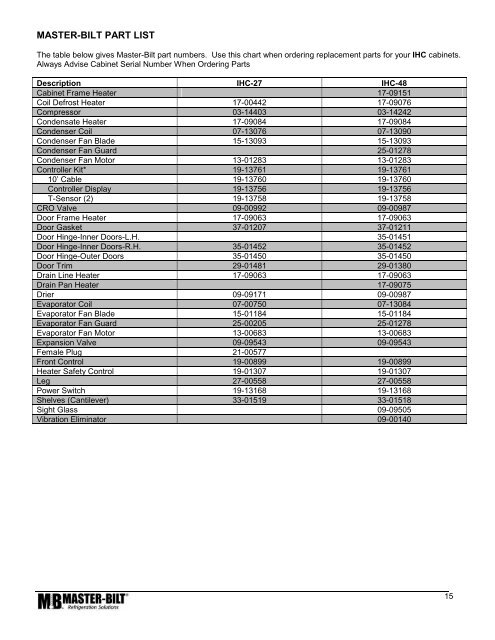
MASTER-BILT PART LISTThe table below gives <strong>Master</strong>-<strong>Bilt</strong> part numbers. Use this chart when ordering replacement parts for your IHC cabinets.Always Advise Cabinet Serial Number When Ordering PartsDescription IHC-27 IHC-48Cabinet Frame Heater 17-09151Coil Defrost Heater 17-00442 17-09076Compressor 03-14403 03-14242Condensate Heater 17-09084 17-09084Condenser Coil 07-13076 07-13090Condenser Fan Blade 15-13093 15-13093Condenser Fan Guard 25-01278Condenser Fan Motor 13-01283 13-01283Controller Kit* 19-13761 19-1376110’ Cable 19-13760 19-13760Controller Display 19-13756 19-13756T-Sensor (2) 19-13758 19-13758CRO Valve 09-00992 09-00987Door Frame Heater 17-09063 17-09063Door Gasket 37-01207 37-01211Door Hinge-Inner Doors-L.H. 35-01451Door Hinge-Inner Doors-R.H. 35-01452 35-01452Door Hinge-Outer Doors 35-01450 35-01450Door Trim 29-01481 29-01380Drain Line Heater 17-09063 17-09063Drain Pan Heater 17-09075Drier 09-09171 09-00987Evaporator Coil 07-00750 07-13084Evaporator Fan Blade 15-01184 15-01184Evaporator Fan Guard 25-00205 25-01278Evaporator Fan Motor 13-00683 13-00683Expansion Valve 09-09543 09-09543Female Plug 21-00577Front Control 19-00899 19-00899Heater Safety Control 19-01307 19-01307Leg 27-00558 27-00558Power Switch 19-13168 19-13168Shelves (Cantilever) 33-01519 33-01518Sight Glass 09-09505Vibration Eliminator 09-0014015