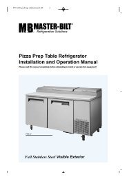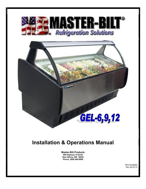
Installation & Operations Manual - Master-Bilt
Installation & Operations Manual - Master-Bilt
Installation & Operations Manual - Master-Bilt

You also want an ePaper? Increase the reach of your titles
YUMPU automatically turns print PDFs into web optimized ePapers that Google loves.
PRE-INSTALLATION INSTRUCTIONSINSPECTION FOR SHIPPING DAMAGEYou are responsible for filing all freight claims with the delivering truck line. Inspect all cartons and crates for damage assoon as they arrive. If damage is noted to shipping crates or cartons or if a shortage is found, note this on the bill of lading(all copies) prior to signing.If damage is discovered when the cabinet is uncrated, immediately call the delivering truck line and follow up the call with awritten report indicating concealed damage to your shipment. Ask for an immediate inspection of your concealed damageitem. Crating material must be retained to show the inspector from the truck line.INSTALLATION INSTRUCTIONSGENERAL INSTRUCTIONS1. Be sure the equipment is properly installed by competent service people.2. Keep the equipment clean and sanitary so it will meet your local sanitation codes. Clean the cabinet with a milddetergent and water, then rinse.3. Rotate your stock so that older stock does not accumulate. This is especially important for ice cream. A "First-In,First-Out" rotation practice will keep the products in good salable condition.4. Do not place product in the case when it is soft or partially thawed. Also, product should not be put in the case forat least 4 hours after it is started.5. Stock cases as quickly as possible, exposing only small quantities to store temperatures for short periods of time.6. When replacing burned out fluorescent tubes, be sure that the electrical power to the lighting circuit is turned off.5
NOTICE TO STORE OWNERS / MANAGERSWARNING!Moisture or liquid around or under the cabinet is a potential slip/fall hazard for persons walking by or working inthe general area of the cabinet. Any cabinet malfunction or housekeeping problem that creates a slip/fall hazardaround or under the cabinet should be corrected immediately.If moisture or liquid is observed around or under a <strong>Master</strong>-<strong>Bilt</strong> cabinet, an immediate investigation should be made byqualified personnel to determine the source of the moisture or liquid. The investigation should determine if the cabinet ismalfunctioning or if there is a drainpipe leaking.CABINET CLEANING PROCEDURESWARNING!To avoid electrical shock, disconnect main power supplies to the merchandiserbefore beginning this procedure. May have more than one disconnect switch.The exterior of the cabinet should simply be wiped clean with a Warm damp cloth daily. This will be sufficient to keep themerchandiser looking its finest. Do not use a brush, scouring pad, or any abrasive material on the painted surfaces!To clean the interior of the cabinet, the condensing unit and power to the merchandiser fans, lights, and heaters should beshut off. Disconnect all power before cleaning! All product in the cabinet should be removed and stored in anappropriate facility. All shelving, trays, Pans, etc. should be removed and cleaned separately. For cleaning the airdischarge honey comb in the back wall. Romove the honey comb retainer, that’s hold the honey comb in place, byunscrewing all the thrump scews. Gently pull out all the honey combs. Wash with hot warm water only and carefullyreplace it back. Be sure the honey combs is dry before putting it back inplace to provent from ice build up blocking the airflow.The interior (as well as the exterior) of the cabinet may be cleaned with a germicidal detergent at the manufacturer’srecommended concentration. Do not use any ammonia-based products as this may damage the electricalcomponents in the cabinet. Again, do not use a brush, scouring pad, or any abrasive material on the painted surfaces.Use a soft brush or cleaner pad for built-up dirt, stains, or spills. Remove only the necessary mechanical parts to accessthe evaporator coil and fan housing. Care should be taken not to unnecessarily soak fan motors, electrical connections,controls, or any wire raceway. Wipe all surfaces with a damp cloth. A sanitizer should then be thoroughly sprayed ontothe surfaces and again wiped with a damp cloth.Remove only the necessary mechanical parts to access the condenser coil and compressor housing. Care should againbe taken not to unnessarily soak fan motors, electrical connections, time clock, ballasts, or any wire raceway. Check thecondenser coil to insure that it is not clogged with dirt, dust, or lint. A dirty or clogged condenser coil will result indiminished performance of the cabinet. The condenser should be brushed with a plastic bristled brush. For dust or dirtthat has accumulated deep inside the condenser, use compressed air to blow the dirt through the coil. Do not let dust ordirt accumulate on the fan blades. If dust or dirt is noticeable, simply wipe the fan blades with a damp cloth as with othersurfaces. After cleaning, replace any equipment that was previously removed and started the condensing unit and returnpower to the lights, fans, and heaters.CLEANING: As a regular maintenance routine, the condenser coil should be cleaned approx every 6 to 12 months,depending on store conditions.Keep the equipment clean and sanitary so it will meet your local sanitation codes. Wipe up all spills, clean with water anda mild detergent, then rinse with clean water. Wipe the exterior and gasket area as needed.6
Cabinet Monthly Checklist1. Check condenser coil, clean if necessary.2. Check service valve packing for leaks evident by oiltraces.3. Check for obstruction restricting air flow over theevaporator coil and the condenser coil. Insure thatthe air intake is not obstructed.4. Check for excessive noise5. Check for proper temperature, adjust ifnecessary.6. Check for proper operation sequence innormal refrigeration cycle and defrost cycle(when applicable).EXTERNAL CLEANINGClean the front and side glass panels, and the end panels and serving surfaces with warm water and a milddetergent. Never use steel wool, abrasives, glass paper, or similar products. Never use acids, chlorines, ammonia,etc. as it could damage the cabinet surface.WEEKLY DEFROSTINGFor enhanced performance and efficiency, the <strong>Master</strong>-<strong>Bilt</strong> GEL series should be defrosted weekly for an extendedperiod (at least twelve hours). To achieve this defrost, the cabinet should have a manual defrost first. Press andhold the button labeled “MAN DEF” for ten seconds on the control. (See the section of this manual labeledELECTRONIC REFRIGERATION CONTROL). After the cabinet starts a defrost cycle, wait about 15 minutes, thendisconnect the power supply to the cabinet and let the cabinet stand for this prolonged period. This will ensure thatall ice has been defrosted and drained from the evaporator and storage area.MECHANICALRemove front and rear grille and check refrigeration lines to see that they are free (not touching each other orcompressor). Spin condenser fan blade to see that it is free.Check that all service valves (2) are open. The springs are secured for shipping by either tightening bolts. Loosenthe hold-down bolts so that the compressor floats freely. Check all refrigeration lines and electrical conduit forrubbing or chaffing, paying particular attention to area where lines enter the cabinet.Remove cabinet from crate base and slide into location. Cabinet must be level from side to side and front to back forcorrect draining of coil pan and for self-closing doors to operate correctly.7
HOT GAS REFRIGERANT PIPINGThe <strong>Master</strong>-<strong>Bilt</strong> GEL series ofcabinets is equipped with a hot gasdefrost. This involves some extrapiping from an electrical or airdefrost system.The diagrams here show only onecondensing unit and one set ofconnection points at the evaporator.It should be noted, however, that theGEL-9 and GEL-12 have twocondensing units, each unit havingevaporator connection points at eachend of the evaporator.There are two solenoid valves. The3/8” solenoid valve is normallyclosed and the 5/8” solenoid valve isnormally open.During a normal refrigeration cyclethe 3/8” valve is closed, the 5/8”valve is open and refrigerant isallowed to flow through thecondenser coil and the expansionvalve before flowing through theevaporator coil. See the figure onthe next page.During a defrost cycle, both valvesare energized. The 3/8” valveopens, the 5/8” valve closes, thecondenser coil and the expansionvalve are bypassed and “hot gas” isintroduced to the evaporator coil fordefrosting. See the figure on thenext page.10
MASTER-BILT ELECTRONIC REFRIGERATION CONTROLOPERATIONCompressor When power is first turned on to the control, the LED indicator under COMP on the displaystarts blinking. After one-minute delay the compressor comes on. The COMP LED indicator stays onwhile compressor relay is energized. Display will show actual box temperature. Figure 4 is the displaylayout.The compressor will be cycled off when the actual box temperature reaches its set point. The COMPindicator will be off.Fig. 4 – Display Lay-outFan- The fans will run constantly except when a defrost is initiated, or when the evaporator temp is abovethe 30 o F. When in defrost mode the fan is off until the end of the defrost and the 2 minute drip time haspassed. There is 4 minutes delay after a defrost before the fan comes on. The difference of theevaporator and room temperature of more than 9 o F will override the fan delay. FAN LED indicator is onwhile FAN relay is energized.Defrost- The control uses hot gases defrost every two hours. During defrost the display will show dF andthe LED indicator under DF in on.MANUAL DEFROST1. Push this DEFROST key for more than 2 seconds and a manual defrost will start.2. While in defrost, Push and hold the DEFROST key for more than 5 seconds and thecontroller will end the defrost cycle. The controller will then enter drip mode for 2 minutes. The DFled is flashing in drip mode.HOW TO SEE THE SETPOINT (Box temperature cut-out)1. Push and immediately release the SET key: the display will show the Setpoint value;2. Push and immediately release the SET key or wait for 5 seconds to display the probe value(actual box temperature) again.HOW TO CHANGE THE SETPOINT1. Push the SET key for more than 2 seconds to change the Set point value;2. The value of the set point will be displayed and the LED under COMP starts blinking;3. To change the Set value push the UP ▲ or DOWN▼ arrows within 10s.4. To memorize the new set point value push the SET key again or wait 10s.12
HOW TO CHANGE a parameter valueEnter the Programming mode by pressing the SET and DOWN ▼ keys for 3seconds (LEDs under DEF and COMP start blinking).1. Select the required parameter by pushing the UP ▲ or DOWN▼ arrows2. Press the “SET” key to display its value (now only the COMP LED is blinking)3. Use “UP” or “DOWN” to change its value4. To exit: Press SET + UP ▲ or wait 15s without pressing a key.NOTE 1: The set value is stored even when the procedure is exited by waiting the time-out to expire.NOTE 2: <strong>Master</strong>-<strong>Bilt</strong>’s SETPOINT is set at a recommended –10°F at the factory for low temperature(LT) and+35 o F for medium temperature(MT) application.NOTE 3: To scroll down the parameters without changing them, press the DOWN button.LIST OF PARAMETERSHere is a list of the parameters the value of which can be changed in the programming mode, as well astheir ranges.ParameterMinimumtemperature alarmlimitMaximumtemperature alarmlimitDisplaySymbolALAUDescription Range <strong>Master</strong>-<strong>Bilt</strong>’sSettingWhen this temperature isreached the alarm is enabled -58 to 230°F -25after a delayWhen this temperature isreached the alarm is enabled -58 to 230°F 20after a delayALARM SIGNALSMessage Cause Outputs“P1” Room probe failure Compressor output according to par. “Con” and “COF”“P2” Evaporator probe failure Defrost end is timed“HA” Maximum temperature alarm Outputs unchanged.“LA” Minimum temperature alarm Outputs unchanged.“dA” Door open Compressor and fans restarts“EA” External Alarm Output unchanged“CA” Serious External alarm(i1F=bAL) All output off“CA” Pressure switch alarm (i1F=PAL) Outputs unchanged.NOTE:Probe alarms “P1” and “P2” start some seconds after the fault in the related probe; theyautomatically stop some seconds after the probe restarts normal operation. Check connectionsbefore replacing the probe.Temperature alarms “HA” and “LA” automatically stop as soon as the thermostat temperaturereturns to normal values and when defrost starts.13
SERVICE INSTRUCTIONS1. High head pressure and high back pressure:A. Condenser coil clogged or restrictedB. Condenser fan motor defective.C. Air discharge in front of cabinet restricted.2. Low back pressure and low head pressure:A. Restriction in system.B. Refrigerant undercharged.C. Leak in system3. Pressure normal – cabinet warm:A. Coil blocked with frost (see #4).B. Refrigerant undercharged.C. Control set too warm.4. Cabinet not cycling – coil blocked with frost:A. Defective temperature controller.B. Refrigerant overcharged.C. Evaporator Fan Motor defective.D. Hot gas defrost duration not long enough or too few defrosts.E. Condenser clogged.F. Condenser fan motor defective.G. Hot gas solenoid valve defective5. Copressor starts and runs – but cycles on overload:A. Low voltageB. Relay defective.C. Overload defective.14
FINAL CHECK LISTA. Check operating pressures.B. Check electrical requirements of unit to supply voltage.C. Set temperature control for desired temperature range.D. Check sight glass for proper refrigerant charge, if provided.E. Check system for proper defrost settings and operation.F. Check condensing unit for vibrating or rubbing tubing. Dampen and clamp as required.G. All valves should be completely opened counter-clockwise.H. Check packing nuts on all service valves.I. Replace all service valve caps and latch unit covers.MASTER-BILT PART LISTThe table below gives <strong>Master</strong>-<strong>Bilt</strong> part numbers. Use this chart when ordering replacement parts for your GELcabinets. Always Advise Cabinet Serial Number When Ordering PartsDescription GEL-6 GEL-9 GEL-12Ballast 23-01709 23-01704 23-0170436” Bulb/Lamp F25T8 23-01577 23-01577(2)24” Bulb/Lamp F32T8 23-01576 (2)Bulb Holder 23-50562(2) 23-50562(4) 23-50562(4)Bulb Shield 25-01274 25-01274 (2) 25-01274 (2)Drain Trough Heater 17-09435 17-09436 17-09437Compressor 03-14985 03-14985 (2) 03-14985 (2)Anti-Sweat Heater Front 17-09432 17-09433 17-09434Anti-Sweat Heater Rear Deck 17-09432 17-09433 17-09434Condenser Coil 07-13076 07-13076 (2) 07-13076 (2)Condenser Fan Blade 15-13093 15-13093 15-13093Condenser Fan Motor 13-01283 13-01283 13-01283Electronic Controller 19-14085 19-14085 19-1408520’ Sensor Assembly 19-13932 19-13932 19-13932CRO Valve 09-00992 09-00992 09-00992Drier 09-09171 09-09171 09-09171Evaporator Coil 07-13313 07-13314 07-13315Evaporator Motor/Blade Assy 13-13199 13-13199 13-131993/8” Solenoid Valve 09-09645 09-09645 09-096455/8” (Hot Gas) Solenoid Valve 09-09826 09-09826 09-09826Expansion Valve 09-09453 09-09453 09-09453Lamp Switch 23-50793 23-50793 23-50793Receiver Tank 09-01162 09-01162 09-01162Contactor 19-13934 19-13934 (2) 19-13934 (2)Time Delay Relay 19-13707 19-1370715
SALE AND DISPOSALOWNER RESPONSIBILITYIf you sell or give away your <strong>Master</strong>-<strong>Bilt</strong> cabinet you must make sure that all safety labels and the <strong>Installation</strong> -Service <strong>Manual</strong> are included with it. If you need replacement labels or manuals, <strong>Master</strong>-<strong>Bilt</strong> will provide them free.Contact the customer service department at <strong>Master</strong>-<strong>Bilt</strong> at (800) 684-8988.The customer service department at <strong>Master</strong>-<strong>Bilt</strong> should be contacted at the time of sale or disposal of your cabinet sorecords may be kept of its new location.16