VSL Technical Report.. - Free
VSL Technical Report.. - Free
VSL Technical Report.. - Free

You also want an ePaper? Increase the reach of your titles
YUMPU automatically turns print PDFs into web optimized ePapers that Google loves.
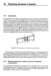
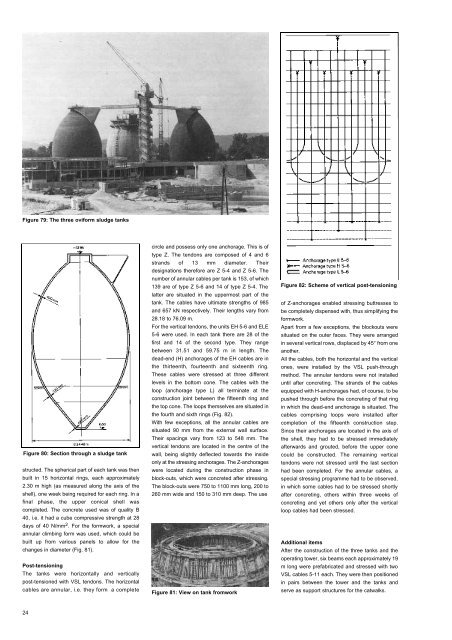
Figure 79: The three oviform sludge tanks<br />
Figure 80: Section through a sludge tank<br />
structed. The spherical part of each tank was then<br />
built in 15 horizontal rings, each approximately<br />
2.30 m high (as measured along the axis of the<br />
shell), one week being required for each ring. In a<br />
final phase, the upper conical shell was<br />
completed. The concrete used was of quality B<br />
40, i.e. it had a cube compressive strength at 28<br />
days of 40 N/mm 2 . For the formwork, a special<br />
annular climbing form was used, which could be<br />
built up from various panels to allow for the<br />
changes in diameter (Fig. 81).<br />
Post-tensioning<br />
The tanks were horizontally and vertically<br />
post-tensioned with <strong>VSL</strong> tendons. The horizontal<br />
cables are annular, i.e. they form a complete<br />
circle and possess only one anchorage. This is of<br />
type Z. The tendons are composed of 4 and 6<br />
strands of 13 mm diameter. Their<br />
designations therefore are Z 5-4 and Z 5-6. The<br />
number of annular cables per tank is 153, of which<br />
139 are of type Z 5-6 and 14 of type Z 5-4. The<br />
latter are situated in the uppermost part of the<br />
tank. The cables have ultimate strengths of 985<br />
and 657 kN respectively. Their lengths vary from<br />
28.18 to 76.09 m.<br />
For the vertical tendons, the units EH 5-6 and ELE<br />
5-6 were used. In each tank there are 28 of the<br />
first and 14 of the second type. They range<br />
between 31.51 and 59.75 m in length. The<br />
dead-end (H) anchorages of the EH cables are in<br />
the thirteenth, fourteenth and sixteenth ring.<br />
These cables were stressed at three different<br />
levels in the bottom cone. The cables with the<br />
loop (anchorage type L) all terminate at the<br />
construction joint between the fifteenth ring and<br />
the top cone. The loops themselves are situated in<br />
the fourth and sixth rings (Fig. 82).<br />
With few exceptions, all the annular cables are<br />
situated 90 mm from the external wall surface.<br />
Their spacings vary from 123 to 548 mm. The<br />
vertical tendons are located in the centre of the<br />
wall, being slightly deflected towards the inside<br />
only at the stressing anchorages. The Z-anchorages<br />
were located during the construction phase in<br />
block-outs, which were concreted after stressing.<br />
The block-outs were 750 to 1100 mm long, 200 to<br />
260 mm wide and 150 to 310 mm deep. The use<br />
Figure 81: View on tank fromwork<br />
Figure 82: Scheme of vertical post-tensioning<br />
of Z-anchorages enabled stressing buttresses to<br />
be completely dispensed with, thus simplifying the<br />
formwork.<br />
Apart from a few exceptions, the blockouts were<br />
situated on the outer faces. They were arranged<br />
in several vertical rows, displaced by 45° from one<br />
another.<br />
All the cables, both the horizontal and the vertical<br />
ones, were installed by the <strong>VSL</strong> push-through<br />
method. The annular tendons were not installed<br />
until after concreting. The strands of the cables<br />
equipped with H-anchorages had, of course, to be<br />
pushed through before the concreting of that ring<br />
in which the dead-end anchorage is situated. The<br />
cables comprising loops were installed after<br />
completion of the fifteenth construction step.<br />
Since their anchorages are located in the axis of<br />
the shell, they had to be stressed immediately<br />
afterwards and grouted, before the upper cone<br />
could be constructed. The remaining vertical<br />
tendons were not stressed until the last section<br />
had been completed. For the annular cables, a<br />
special stressing programme had to be observed,<br />
in which some cables had to be stressed shortly<br />
after concreting, others within three weeks of<br />
concreting and yet others only after the vertical<br />
loop cables had been stressed.<br />
Additional items<br />
After the construction of the three tanks and the<br />
operating tower, six beams each approximately 19<br />
m long were prefabricated and stressed with two<br />
<strong>VSL</strong> cables 5-11 each. They were then positioned<br />
in pairs between the tower and the tanks and<br />
serve as support structures for the catwalks.<br />
24