VSL Technical Report.. - Free
VSL Technical Report.. - Free
VSL Technical Report.. - Free

You also want an ePaper? Increase the reach of your titles
YUMPU automatically turns print PDFs into web optimized ePapers that Google loves.
and 148). It rests on an octagonal substructure.<br />
The silo comprises 4 buttresses for anchoring the<br />
post-tensioning tendons. Its capacity is approx.<br />
7000 m3. The silo wall was built by the slipforming<br />
method (Fig. 149). On top of the silo there is a<br />
steel structure for the charging equipment.<br />
Post-tensioning<br />
The silo wall is post-tensioned with 160 <strong>VSL</strong><br />
cables EE 5-7 Dyform, each 24.70 m in length.<br />
Each cable extends around one half of the<br />
circumference. The distance of the cables from<br />
the outer face is 70 mm and the cable spacing<br />
varies from 450 to 1000 mm.<br />
Figure 150: Buttress with anchorages <strong>VSL</strong> type B<br />
3.2.7. Coal silos, Gillette, Wy., USA<br />
Owner North Antelope Coal Co.,<br />
St. Louis, Mo.<br />
Engineer SMH Engineering Inc.,<br />
Lakewood, Col.<br />
Contractor The Nicholson Co., Marietta,<br />
Ohio<br />
Posttensioning<br />
<strong>VSL</strong> Corporation, Dallas, Tx.<br />
Years of<br />
construction 1982-1983<br />
Introduction<br />
At the North Antelope coal mine three silos each<br />
of 20 000 tonnes capacity were built between<br />
September 1982 and June 1983. Beneath the<br />
silos there are rail tracks on which the trains move<br />
forward slowly during loading with coal.<br />
Details of the structures<br />
Each silo has an internal diameter of 21.34 m and<br />
a wall thickness of 350 mm. The height of the wall<br />
is 60.15 m and there are 4 buttresses each 1.98<br />
m wide for anchoring the tendons. The roof is of<br />
steel girders, resting in recesses in the silo wall,<br />
and of a profiled metal sheet covered with<br />
concrete which projects slightly beyond the silo<br />
wall. The roof is not connected with the wall, but<br />
the wall is fixed in the substructure.<br />
Post-tensioning<br />
The silos are post-tensioned with cables 5-4, 5-5<br />
and 5-6. The largest units, cables 5-6, are located<br />
in the central region of the wall. All the tendons<br />
extend around onehalf of the circumference. For<br />
the anchorages, <strong>VSL</strong> type B (Fig. 150) was<br />
chosen. The distance from the outer face of the<br />
silo wall to the axes of the cables is 89 mm and<br />
the cable spacings vary from 560 mm minimum to<br />
1520 mm maximum.<br />
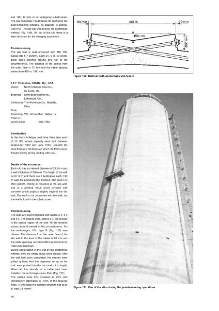
During construction of the wall by the slipforming<br />
method, only the empty ducts were placed. After<br />
the wall had been completed, the strands were<br />
pulled by hand from the dispenser set up on the<br />
roof, were pushed into the duct and cut to length.<br />
When all the strands of a cable had been<br />
installed, the anchorages were fitted (Fig. 151).<br />
The cables were first stressed to 20% and<br />
immediately afterwards to 100% of the required<br />
force. At this stage the concrete strength had to be<br />
at least 24 N/mm 2 .<br />
Figure 151: One of the silos during the post-tensioning operations<br />
46